

SIST EN 1846-3:2026
(Main)Firefighting and rescue service vehicles - Part 3: Permanently installed equipment - Safety and performance
- Abstract
1.1 This document specifies the minimum requirements for safety and performance of some optional specific permanently installed equipment on firefighting and rescue service vehicles, operated by trained persons, as designated in EN 1846 1:2011 and specified in EN 1846 2:2024.
NOTE 1 Categories and mass classes of these vehicles are given in EN 1846 1:2011.
NOTE 2 Vehicle means ground vehicles which can also drive on rails and amphibious vehicles.
The permanently installed equipment covered by this document is given below:
- water installation;
- additive installation;
- monitor;
- equipment gantries;
- demounting systems.
This document covers also the use of wireless control systems.
NOTE 3 This document is assumed to be read in conjunction with any national regulations in force for vehicles using the public roads and with any EU Directives and associated EFTA regulations in force relevant to vehicles and their equipment.
For the purposes of this document, the normal ambient temperature range is –15 °C to +40 °C.
For equipment to be used at temperature outside this temperature range, the particular temperature range is specified by the user. A risk assessment determines any need for additional precautions.
1.2 This document does not deal with the following types of equipment:
- all control systems outside of the cabin related to hook arm system;
- provisions for non-firefighting removable equipment driven by PTO.
1.3 This document deals with the technical requirements to minimize the hazards listed in Annex A which can arise during operational use, routine checking and maintenance of firefighting and rescue service vehicles.
It does not cover the hazards generated by:
- non-permanently installed equipment i.e. portable equipment carried on the vehicle;
- use in potentially explosive atmospheres;
- commissioning and decommissioning;
- noise (as permanently installed equipment cannot be operated separately from the vehicle, this hazard is covered in EN 1846 2:2024);
- electromagnetic compatibility;
- cyber security;
- cyber safety.
Additional measures not dealt with in this document can be necessary for specific use (e.g. fire in natural environment, flooding, etc.).
1.4 This document is not applicable to the equipment which is manufactured before its date of publication by CEN.
- Status
- Published
- Public Enquiry End Date
- 29-Oct-2025
- Publication Date
- 02-Nov-2026
- Technical Committee
- POZ - Požarna varnost
- Current Stage
- 6060 - National Implementation/Publication (Adopted Project)
- Start Date
- 02-Nov-2026
- Due Date
- 07-Jan-2027
- Completion Date
- 03-Nov-2026

SIST EN 1846-3:2026 is the Slovenian standard for firefighting and rescue service vehicles, Part 3, published by SIST. It sets minimum safety and performance requirements for selected permanently installed equipment on these vehicles, for use by trained persons. The document is written for manufacturers, vehicle integrators, and buyers who need to specify, verify, or assess water systems, additive systems, monitors, bracket assemblies, and demounting equipment.
What does SIST EN 1846-3:2026 specify?
SIST EN 1846-3:2026 specifies safety and performance requirements for optional permanently installed equipment on firefighting and rescue service vehicles designated in EN 1846-1 and specified in EN 1846-2. It covers equipment installed on vehicles operated by trained persons, including use with wireless control systems.
The scope covers:
- water installation
- additive installation
- monitor
- equipment gantries
- demounting systems
The document applies with a normal ambient temperature range of -15 °C to +40 °C. If the equipment is intended for other temperatures, the user specifies the range and a risk assessment determines whether extra precautions are needed.
The document excludes:
- control systems outside the cabin related to hook arm systems
- provisions for non-firefighting removable equipment driven by PTO
It also keeps out several hazards from its own technical coverage, including portable equipment carried on the vehicle, use in potentially explosive atmospheres, commissioning and decommissioning, noise, electromagnetic compatibility, cyber security, and cyber safety.
The document is organized into six main clauses plus informative and normative annexes.
| Annex | What it covers |
|---|---|
| Annex A | Significant hazards linked to the covered equipment |
| Annex B | Theoretical stability calculation for hook arm systems |
| Annex C | Usable capacity of the water tank |
| Annex D | Monitor throw measurement |
| Annex E | Variation of suction height with atmospheric pressure and water temperature |
| Annex F | Examples of other demounting systems |
| Annex ZA | Relationship with Regulation (EU) 2023/1230 |
What are the key requirements of SIST EN 1846-3:2026?
SIST EN 1846-3:2026 combines general machine-safety rules with equipment-specific requirements. Clause 5 is the core of the standard, and it links design, verification, and operating information so that the equipment can be used safely in service, checking, and maintenance.
General safety and control
Clause 5.1 requires permanently installed equipment to fit the chassis specification and not interfere with other installed equipment. Adjustments needed during intended use must be possible without tools, which matters in fireground use where operators need quick changes and simple handling.
Clause 5.2.1 requires the equipment to meet the general safety requirements of EN 1846-2 and to be designed using EN ISO 12100 principles for residual hazards. Each operating position needs a stop control. Hydraulic parts must follow EN ISO 4413 and pneumatic parts EN ISO 4414, while materials and construction must resist corrosion and water or dirt accumulation.
Water installation
Clause 5.2.2 sets the main requirements for water systems. Safety-related control parts for pressure regulation and opening of pressure outlets need required performance level (PL) a, while the hose and outlet system must withstand pressure, stay within the limit pressure, and keep pump speed within the specified limit. In practice, this means the water system must be checked not just for output, but for safe control behavior under load.
The water tank requirements focus on access, stability, and clear status indication. The tank must be serviceable, fitted with a level indicator visible from the pump operating position, and arranged so that filling and baffles do not create instability. Supply and delivery connections must be reachable, identified, and arranged to prevent pressure build-up and unsafe hose connection.
Hosereel systems have specific operational protections: powered rewind needs hold-to-run control, the reel must be visible during rewind, and unintended unwinding must be prevented. That reduces the risk of entanglement and loss of control during hose handling.
Additive installation
Clause 5.2.3 applies similar safety logic to additive systems. Positive pressure proportioning systems (PPPS) and compressed air foam systems (CAFS) must also comply with EN 16327. The installation must withstand pressure, resist corrosion from the additive, and be drainable and flushable.
The tank must have visible level indication, safe filling, and overflow prevention during driving and normal use. Controls and indicators at the pump operating position include foam start/stop, additive level, and mixing control. For users, this means the document expects the additive system to be usable, cleanable, and controllable without guesswork.
Monitor and removable equipment handling
Clause 5.2.4 requires the monitor control system to reach PL b. The monitor must show direction if it is not visible from the operator position, allow opening, closing, movement, and holding in position, and provide warning if it can move unexpectedly near people. If it is remotely operated while the vehicle is moving, driver-operator communication is required.
Clause 5.2.5 covers bracket assemblies for removable equipment. They must hold equipment securely, prevent unintended movement, and remain safe if the power supply fails. For wheeled hosereels and similar equipment, removal must be possible from ground level and by one firefighter, with manual force kept within the specified limit. This is important for day-to-day deployment and return-to-service tasks.
Hook arm systems, cranes, and extendable equipment
Clause 5.2.6 sets detailed requirements for hook arm systems and demountables. It requires visual warning, hold-to-run control, stability during loading and unloading, visibility of the demountable and hook, audible warnings, and control-system PL b for non-tipping systems and PL c for tipping systems. The system must also protect hydraulic connections, prevent dangerous contact with hot surfaces, and show the maximum allowable height and gradient information needed by the driver.
Clause 5.2.7 points lifting systems using a crane to EN 12999. Clause 5.2.8 addresses extendable equipment such as masts, requiring risk assessment, visibility of the extremity, and protection against electric hazard where the visual-control approach is not enough.
Performance, use, marking, and instructions
Clause 5.3 checks whether the equipment performs as intended. For water systems, this includes leakage resistance, drainage, frost protection, flushing, output classification, pump function at vehicle cross-axle capability, priming performance, and pressure regulation. For additive systems, it covers mixture accuracy, usable tank capacity, drainage, flushing, and proper connection layout.
Clause 6 requires instruction handbook information, safety warnings, performance data, maintenance guidance, and marking. It also requires specific warnings about overhead power lines, residual risks, suitable liquids for additive systems, and the safe disposal of flushing water where relevant.
What terms does SIST EN 1846-3:2026 define?
- Water installation - the set of components used to collect, store, and deliver water or a water-additive mixture at different pressures and delivery rates.
- Additive installation - the matching set of components for additive collection, storage, and delivery before mixing with water.
- Usable capacity - the volume in a tank that can actually be used by the corresponding pump.
- Monitor - a device used to project extinguishing agents.
- Bracket assembly for removable equipment - a mechanical system, manual or power driven, that helps load, unload, and store equipment.
- Demountable - a specially designed frame with superstructure that can be transported, mounted, and dismounted by a demounting system.
- Demounting system - the vehicle-installed equipment used to mount and dismount a demountable.
- Hold-to-run control device - a control that keeps a function running only while the operator keeps actuating it.
- PL - required performance level, used for the safety-related parts of control systems.
- FPN - normal-pressure pump.
Who uses SIST EN 1846-3:2026?
SIST EN 1846-3:2026 is used by vehicle manufacturers, system integrators, and suppliers of firefighting equipment who design or supply permanently installed water, foam, monitor, or handling systems. It is also used by buyers, specification writers, inspection staff, and safety managers who need to check that the equipment layout, controls, markings, and instructions match the intended use.
The standard is relevant to fire and rescue services, maintenance providers, and safety authorities because it sets the technical basis for safe operation, routine checking, and maintenance of the installed equipment.
What changed in SIST EN 1846-3:2026 from the previous edition?
SIST EN 1846-3:2026 supersedes EN 1846-3:2013. The foreword lists these main changes:
- scope updated, including wireless control systems and revised covered and excluded equipment
- normative references updated and dated
- several term entries updated, and new terms added for mixing system, demountable, and demounting system
- symbols and abbreviated terms moved to Clause 4
- significant hazards moved to Annex A
- required performance levels added for water installation, monitor, bracket assembly, and hook arm system
- ergonomics requirements moved into safety requirements
- water installation and additive installation requirements updated
- new clauses added for lifting system using a crane and extendable equipment
- marking requirements amended
- Annex C and Annex E updated, and Annex F added
- Annex ZA updated to reference Regulation (EU) 2023/1230
Which standards are used with SIST EN 1846-3:2026?
The document relies on several linked standards:
- EN 1846-1:2011 - gives nomenclature and designation for the vehicle categories and mass classes
- EN 1846-2:2024 - provides the common safety and performance requirements used throughout the document
- EN 1028-1:2002+A1:2008 - supports pump classification and requirements for primed fire-fighting centrifugal pumps
- EN 14710-1:2005+A2:2008 - supports pump classification and requirements for pumps without primer
- EN 16327:2014 - applies to PPPS and CAFS
- EN 12999:2020+A1:2025 - applies when the lifting system is a loading crane
- EN ISO 12100:2010 - provides risk assessment and risk reduction principles
- EN ISO 13849-1:2023 and EN ISO 13849-2:2012 - define and validate required performance levels for safety-related control parts
- EN ISO 4413:2010 and EN ISO 4414:2010 - cover hydraulic and pneumatic systems
- EN 60529:1991 - provides the IP Code, including the external equipment protection level used here
- EN 547-2:1996+A1:2008 - supports access-opening dimensions
- EN 659:2003+A1:2008 - provides the firefighter glove context used in ergonomic design
- prEN 15767-1:2025 - applies to monitor assemblies that can also be used as portable monitors
What does the SIST EN 1846-3:2026 document contain?
SIST EN 1846-3:2026 contains detailed verification requirements for safety and performance, not just general statements. Clause 5 includes pressure tests, functional tests, access and visibility checks, stability checks, and control-system performance levels. Annex B gives the stability calculation for hook arm systems, while Annex C gives the method for determining usable water tank capacity by weighing or flowmeter. Annex D provides the monitor throw test method, including the test angle and how to derive effective throw from measured droplet distance. Annex E gives correction data for suction height versus atmospheric pressure and water temperature, and Annex F illustrates examples of other demounting systems.
Relations
- Effective Date
- 01-Dec-2026
- Effective Date
- 21-Oct-2026
- Effective Date
- 21-Oct-2026
- Effective Date
- 21-Oct-2026
- Effective Date
- 21-Oct-2026
Get Certified
Connect with accredited certification bodies for this standard

TÜV Rheinland
TÜV Rheinland is a leading international provider of technical services.

TÜV SÜD
TÜV SÜD is a trusted partner of choice for safety, security and sustainability solutions.

DEKRA Certification Inc.
DEKRA US certification services.
Sponsored listings
Frequently Asked Questions
SIST EN 1846-3:2026 is a standard published by the Slovenian Institute for Standardization (SIST). Its full title is "Firefighting and rescue service vehicles - Part 3: Permanently installed equipment - Safety and performance". This standard covers: 1.1 This document specifies the minimum requirements for safety and performance of some optional specific permanently installed equipment on firefighting and rescue service vehicles, operated by trained persons, as designated in EN 1846 1:2011 and specified in EN 1846 2:2024. NOTE 1 Categories and mass classes of these vehicles are given in EN 1846 1:2011. NOTE 2 Vehicle means ground vehicles which can also drive on rails and amphibious vehicles. The permanently installed equipment covered by this document is given below: - water installation; - additive installation; - monitor; - equipment gantries; - demounting systems. This document covers also the use of wireless control systems. NOTE 3 This document is assumed to be read in conjunction with any national regulations in force for vehicles using the public roads and with any EU Directives and associated EFTA regulations in force relevant to vehicles and their equipment. For the purposes of this document, the normal ambient temperature range is –15 °C to +40 °C. For equipment to be used at temperature outside this temperature range, the particular temperature range is specified by the user. A risk assessment determines any need for additional precautions. 1.2 This document does not deal with the following types of equipment: - all control systems outside of the cabin related to hook arm system; - provisions for non-firefighting removable equipment driven by PTO. 1.3 This document deals with the technical requirements to minimize the hazards listed in Annex A which can arise during operational use, routine checking and maintenance of firefighting and rescue service vehicles. It does not cover the hazards generated by: - non-permanently installed equipment i.e. portable equipment carried on the vehicle; - use in potentially explosive atmospheres; - commissioning and decommissioning; - noise (as permanently installed equipment cannot be operated separately from the vehicle, this hazard is covered in EN 1846 2:2024); - electromagnetic compatibility; - cyber security; - cyber safety. Additional measures not dealt with in this document can be necessary for specific use (e.g. fire in natural environment, flooding, etc.). 1.4 This document is not applicable to the equipment which is manufactured before its date of publication by CEN.
1.1 This document specifies the minimum requirements for safety and performance of some optional specific permanently installed equipment on firefighting and rescue service vehicles, operated by trained persons, as designated in EN 1846 1:2011 and specified in EN 1846 2:2024. NOTE 1 Categories and mass classes of these vehicles are given in EN 1846 1:2011. NOTE 2 Vehicle means ground vehicles which can also drive on rails and amphibious vehicles. The permanently installed equipment covered by this document is given below: - water installation; - additive installation; - monitor; - equipment gantries; - demounting systems. This document covers also the use of wireless control systems. NOTE 3 This document is assumed to be read in conjunction with any national regulations in force for vehicles using the public roads and with any EU Directives and associated EFTA regulations in force relevant to vehicles and their equipment. For the purposes of this document, the normal ambient temperature range is –15 °C to +40 °C. For equipment to be used at temperature outside this temperature range, the particular temperature range is specified by the user. A risk assessment determines any need for additional precautions. 1.2 This document does not deal with the following types of equipment: - all control systems outside of the cabin related to hook arm system; - provisions for non-firefighting removable equipment driven by PTO. 1.3 This document deals with the technical requirements to minimize the hazards listed in Annex A which can arise during operational use, routine checking and maintenance of firefighting and rescue service vehicles. It does not cover the hazards generated by: - non-permanently installed equipment i.e. portable equipment carried on the vehicle; - use in potentially explosive atmospheres; - commissioning and decommissioning; - noise (as permanently installed equipment cannot be operated separately from the vehicle, this hazard is covered in EN 1846 2:2024); - electromagnetic compatibility; - cyber security; - cyber safety. Additional measures not dealt with in this document can be necessary for specific use (e.g. fire in natural environment, flooding, etc.). 1.4 This document is not applicable to the equipment which is manufactured before its date of publication by CEN.
SIST EN 1846-3:2026 is classified under the following ICS (International Classification for Standards) categories: 13.220.10 - Fire-fighting; 43.160 - Special purpose vehicles. The ICS classification helps identify the subject area and facilitates finding related standards.
SIST EN 1846-3:2026 has the following relationships with other standards: It is inter standard links to SIST EN 1846-3:2013, SIST EN 1777:2010, SIST EN 14044:2005+A1:2009, SIST EN 14044:2014, SIST EN 14043:2014. Understanding these relationships helps ensure you are using the most current and applicable version of the standard.
SIST EN 1846-3:2026 is associated with the following European legislation: EU Directives/Regulations: 2023/1230; Standardization Mandates: M/605. When a standard is cited in the Official Journal of the European Union, products manufactured in conformity with it benefit from a presumption of conformity with the essential requirements of the corresponding EU directive or regulation.
SIST EN 1846-3:2026 is available in PDF format for immediate download after purchase. The document can be added to your cart and obtained through the secure checkout process. Digital delivery ensures instant access to the complete standard document.
Standards Content (Sample)
SLOVENSKI STANDARD
01-december-2026
Nadomešča:
SIST EN 1846-3:2013
Gasilska in reševalna vozila - 3. del: Trajno vgrajena oprema - Varnost in zahteve
za delovanje
Firefighting and rescue service vehicles - Part 3: Permanently installed equipment -
Safety and performance
Feuerwehrfahrzeuge - Teil 3: Fest eingebaute Ausrüstung - Sicherheits- und
Leistungsanforderungen
Véhicules des services de secours et de lutte contre l'incendie - Partie 3: Equipements
installés à demeure - Sécurité et performances
Ta slovenski standard je istoveten z: EN 1846-3:2026
ICS:
13.220.10 Gašenje požara Fire-fighting
43.160 Vozila za posebne namene Special purpose vehicles
2003-01.Slovenski inštitut za standardizacijo. Razmnoževanje celote ali delov tega standarda ni dovoljeno.
EN 1846-3
EUROPEAN STANDARD
NORME EUROPÉENNE
October 2026
EUROPÄISCHE NORM
ICS 13.220.10 Supersedes EN 1846-3:2013
English Version
Firefighting and rescue service vehicles - Part 3:
Permanently installed equipment - Safety and
performance
Véhicules des services de secours et de lutte contre Feuerwehrfahrzeuge - Teil 3: Fest eingebaute
l'incendie - Partie 3 : Équipements installés à demeure Ausrüstung - Sicherheits- und Leistungsanforderungen
- Sécurité et performances
This European Standard was approved by CEN on 24 August 2026.
CEN members are bound to comply with the CEN/CENELEC Internal Regulations which stipulate the conditions for giving this
European Standard the status of a national standard without any alteration. Up-to-date lists and bibliographical references
concerning such national standards may be obtained on application to the CEN-CENELEC Management Centre or to any CEN
member.
This European Standard exists in three official versions (English, French, German). A version in any other language made by
translation under the responsibility of a CEN member into its own language and notified to the CEN-CENELEC Management
Centre has the same status as the official versions.
CEN members are the national standards bodies of Austria, Belgium, Bulgaria, Croatia, Cyprus, Czech Republic, Denmark, Estonia,
Finland, France, Germany, Greece, Hungary, Iceland, Ireland, Italy, Latvia, Lithuania, Luxembourg, Malta, Netherlands, Norway,
Poland, Portugal, Republic of North Macedonia, Romania, Serbia, Slovakia, Slovenia, Spain, Sweden, Switzerland, Türkiye and
United Kingdom.
EUROPEAN COMMITTEE FOR STANDARDIZATION
COMITÉ EUROPÉEN DE NORMALISATION
EUROPÄISCHES KOMITEE FÜR NORMUNG
CEN-CENELEC Management Centre: Rue de la Science 23, B-1040 Brussels
© 2026 CEN All rights of exploitation in any form and by any means reserved Ref. No. EN 1846-3:2026 E
worldwide for CEN national Members.
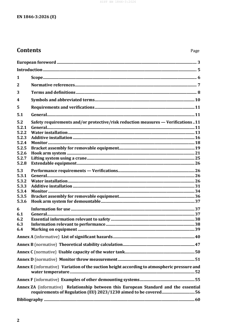
Contents Page
European foreword . 3
Introduction . 5
1 Scope . 6
2 Normative references . 7
3 Terms and definitions . 8
4 Symbols and abbreviated terms . 10
5 Requirements and verifications . 11
5.1 General. 11
5.2 Safety requirements and/or protective/risk reduction measures — Verifications . 11
5.2.1 General. 11
5.2.2 Water installation . 13
5.2.3 Additive installation . 16
5.2.4 Monitor . 18
5.2.5 Bracket assembly for removable equipment. 19
5.2.6 Hook arm system . 21
5.2.7 Lifting system using a crane . 25
5.2.8 Extendable equipment . 26
5.3 Performance requirements — Verifications. 26
5.3.1 General. 26
5.3.2 Water installation . 26
5.3.3 Additive installation . 31
5.3.4 Monitor . 34
5.3.5 Bracket assembly for removable equipment. 36
5.3.6 Hook arm system for demountable . 37
6 Information for use . 37
6.1 General. 37
6.2 Essential information relevant to safety . 38
6.3 Information relevant to performance . 38
6.4 Marking on equipment . 39
Annex A (informative) List of significant hazards . 40
Annex B (normative) Theoretical stability calculation . 47
Annex C (normative) Usable capacity of the water tank . 50
Annex D (normative) Monitor throw measurement . 51
Annex E (informative) Variation of the suction height according to atmospheric pressure and
water temperature . 52
Annex F (informative) Examples of other demounting systems . 55
Annex ZA (informative) Relationship between this European Standard and the essential
requirements of Regulation (EU) 2023/1230 aimed to be covered . 56
Bibliography . 60
European foreword
This document (EN 1846-3:2026) has been prepared by Technical Committee CEN/TC 192 “Fire and
Rescue Service Equipment”, the secretariat of which is held by BSI.
This European Standard shall be given the status of a national standard, either by publication of an
identical text or by endorsement, at the latest by April 2027, and conflicting national standards shall be
withdrawn at the latest by April 2027.
Attention is drawn to the possibility that some of the elements of this document may be the subject of
patent rights. CEN shall not be held responsible for identifying any or all such patent rights.
This document supersedes EN 1846-3:2013.
This document contains the following significant technical changes compared to EN 1846-3:2013:
— scope: the list of permanently installed equipment covered (use of wireless control systems included)
and the list of the equipment not covered have been updated;
— all notes recalling Directives and Regulations references have been removed;
— throughout the document, the meaning of sentences containing “may” and “can” has been analysed
and changes made where necessary;
— the normative references have been updated and dated;
— term entries 3.2 (additive), 3.3 (usable capacity) and 3.6 (bracket assembly for removable
equipment) have been amended to use the same wording as in this document ;
— in 3.1.10, the term and its definition have been amended;
— definitions “installed water pump” (3.1.5), “installed additive pump” (3.2.2) and “demountable” (3.8)
have been updated;
— definitions of water tank capacity (3.3) and demounting system (3.9) have been added ;
— symbols and abbreviated terms are now in Clause 4 (instead of Annex A);
— the list of significant hazards is now in Annex A (instead of Clause 4);
— Required Performance Levels (PL ) have been added in 5.2.2 (Water installation), 5.2.4 (Monitor),
r
5.2.5 (Bracket assembly for removable equipment) and 5.2.6.14 (Hook arm system);
— ergonomics requirements are now in 5.2 “Safety requirement” instead of 5.3 “Performance
requirements”;
— requirements for indicators visible from the pump operating position (5.2.1.8) have been updated;
— requirements for water installation (5.2.2 and 5.3.2) have been updated;
— requirements for additive installation (5.2.3 and 5.3.3) have been updated;
— safety requirements (5.2.4) and performance requirements (5.3.4) for monitor have been updated;
— 5.2.7 (Lifting system using a crane) has been added;
— 5.2.8 (Extendable equipment) has been added;
— in 5.3.2.1.5, alternatively to the height the delivery rate and pressure can be measured using the
geodetic nominal suction height;
— Table 3 (Priming time) has been updated;
— 6.4 (Marking on equipment) has been amended;
— Annex C (Usable capacity of the water tank) has been updated;
— Annex E (Variation of the suction height) has been added;
— Annex F (Examples of other demounting systems) has been added;
— Annex ZA now refers to Regulation (EU) 2023/1230.
This document has been prepared under a standardization request addressed to CEN by the European
Commission. The Standing Committee of the EFTA States subsequently approves these requests for its
Member States.
For the relationship with EU Legislation, see informative Annex ZA, which is an integral part of this
document.
Any feedback and questions on this document should be directed to the users’ national standards body.
A complete listing of these bodies can be found on the CEN website.
According to the CEN-CENELEC Internal Regulations, the national standards organisations of the
following countries are bound to implement this European Standard: Austria, Belgium, Bulgaria, Croatia,
Cyprus, Czech Republic, Denmark, Estonia, Finland, France, Germany, Greece, Hungary, Iceland, Ireland,
Italy, Latvia, Lithuania, Luxembourg, Malta, Netherlands, Norway, Poland, Portugal, Republic of North
Macedonia, Romania, Serbia, Slovakia, Slovenia, Spain, Sweden, Switzerland, Türkiye and the United
Kingdom.
Introduction
This document is a type-C standard as stated in EN ISO 12100.
This document is of relevance, in particular, for the following stakeholder groups representing the market
players with regard to machinery safety:
— machine manufacturers (small, medium and large enterprises);
— health and safety bodies (regulators, accident prevention organizations, market surveillance, etc.).
Others can be affected by the level of machinery safety achieved with the means of the document by the
above-mentioned stakeholder groups:
— machine users/employers (small, medium and large enterprises);
— machine users/employees (e.g. trade unions, organizations for people with special needs);
— service providers, e.g. for maintenance (small, medium and large enterprises);
— consumers (in the case of machinery intended for use by consumers).
The above-mentioned stakeholder groups have been given the possibility to participate at the drafting
process of this document.
The machinery concerned and the extent to which hazards, hazardous situations or hazardous events are
covered are indicated in the Scope of this document.
When requirements of this type-C standard are different from those which are stated in type-A or type-B
standards, the requirements of this type-C standard take precedence over the requirements of the other
standards for machines that have been designed and built according to the requirements of this type-C
standard.
While producing this document it was assumed that, due to the European regulations on the approval of
vehicles for use on public roads, fire fighting vehicles still comply with:
— EMC requirements;
— cyber security requirements.
Therefore, EMC and cyber security are not further considered in this document.
1 Scope
1.1 This document specifies the minimum requirements for safety and performance of some optional
specific permanently installed equipment on firefighting and rescue service vehicles, operated by trained
persons, as designated in EN 1846-1:2011 and specified in EN 1846-2:2024.
NOTE 1 Categories and mass classes of these vehicles are given in EN 1846-1:2011.
NOTE 2 Vehicle means ground vehicles which can also drive on rails and amphibious vehicles.
The permanently installed equipment covered by this document is given below:
— water installation;
— additive installation;
— monitor;
— equipment gantries;
— demounting systems.
This document covers also the use of wireless control systems.
NOTE 3 This document is assumed to be read in conjunction with any national regulations in force for vehicles
using the public roads and with any EU Directives and associated EFTA regulations in force relevant to vehicles and
their equipment.
For the purposes of this document, the normal ambient temperature range is –15 °C to +40 °C.
For equipment to be used at temperature outside this temperature range, the particular temperature
range is specified by the user. A risk assessment determines any need for additional precautions.
1.2 This document does not deal with the following types of equipment:
— all control systems outside of the cabin related to hook arm system;
— provisions for non-firefighting removable equipment driven by PTO.
1.3 This document deals with the technical requirements to minimize the hazards listed in Annex A which
can arise during operational use, routine checking and maintenance of firefighting and rescue service
vehicles.
It does not cover the hazards generated by:
— non-permanently installed equipment i.e. portable equipment carried on the vehicle;
— use in potentially explosive atmospheres;
— commissioning and decommissioning;
— noise (as permanently installed equipment cannot be operated separately from the vehicle, this
hazard is covered in EN 1846-2:2024);
— electromagnetic compatibility;
— cyber security;
— cyber safety.
Additional measures not dealt with in this document can be necessary for specific use (e.g. fire in natural
environment, flooding, etc.).
1.4 This document is not applicable to the equipment which is manufactured before its date of publication
by CEN.
2 Normative references
The following documents are referred to in the text in such a way that some or all of their content
constitutes requirements of this document. For dated references, only the edition cited applies. For
undated references, the latest edition of the referenced document (including any amendments) applies.
EN 547-2:1996+A1:2008, Safety of machinery — Human body measurements — Part 2: Principles for
determining the dimensions required for access openings
EN 659:2003+A1:2008, Protective gloves for firefighters
EN 1028-1:2002+A1:2008, Fire-fighting pumps — Fire-fighting centrifugal pumps with primer — Part 1:
Classification — General and safety requirements
EN 1846-1:2011, Firefighting and rescue service vehicles — Part 1: Nomenclature and designation
EN 1846-2:2024, Firefighting and rescue service vehicles — Part 2: Common requirements — Safety and
performance
EN 12999:2020+A1:2025, Cranes — Loader cranes
EN 14710-1:2005+A2:2008, Fire-fighting pumps — Fire-fighting centrifugal pumps without primer —
Part 1: Classification, general and safety requirements
EN 15767-1:2026, Portable equipment for projecting extinguishing agents and firefighting support
operations — Portable monitors — Part 1: General requirements for portable monitor assemblies
EN 16327:2014, Fire-fighting — Positive-pressure proportioning systems (PPPS) and compressed-air foam
systems (CAFS)
EN 60529:1991, Degrees of protection provided by enclosures (IP Code) (IEC 6059:1989)
EN ISO 4413:2010, Hydraulic fluid power — General rules and safety requirements for systems and their
components (ISO 4413:2010)
EN ISO 4414:2010, Pneumatic fluid power — General rules and safety requirements for systems and their
components (ISO 4414:2010)
EN ISO 12100:2010, Safety of machinery — General principles for design — Risk assessment and risk
reduction (ISO 12100:2010)
EN ISO 13849-1:2023, Safety of machinery — Safety-related parts of control systems — Part 1: General
principles for design (ISO 13849-1:2023)
As impacted by EN 659:2003+A1:2008/AC:2009.
As impacted by EN 60529:1991/A1:2000 and EN 60529:1991/A2:2013, and EN 60529:1991/AC:2016-12,
EN 60529:1991/corrigendum May 1993, and EN 60529:1991/A2:2013/AC:2019-02.
3 Terms and definitions
For the purposes of this document, the terms and definitions given in EN 1846-1:2011, EN 1846-2:2024
and the following apply.
ISO and IEC maintain terminology databases for use in standardization at the following addresses:
— ISO Online browsing platform: available at https://www.iso.org/obp/
— IEC Electropedia: available at https://www.electropedia.org/
3.1
water installation
combination of components for the collection, storage and delivery of water and/or water-additive
mixture at varying pressures and delivery rates
3.1.1
classification of the water installation
combination of the delivery rate Q specified at pressure p and at specified height d
1 a1
3.1.2
height
d
difference of level between the standing surface of the vehicle and the water surface at the time of a
pumping appliance suction operation
3.1.3
standing surface of the vehicle
surface on which the vehicle wheels are resting when it is operating
3.1.4
standing surface of the operator
surface on which the operator stands
3.1.5
installed water pump
pump for water permanently installed on a vehicle and driven by the power supply of the vehicle or by
its own power supply
3.1.6
installed water tank
container for storage of water for fire service purposes
3.1.7
supply and delivery connections for water
inlet and outlet devices for joining hoses to the pipework installation
3.1.8
pipework installation for water
system linking the installed water pump(s), the installed water tank(s) and the supply and delivery
connections
3.1.9
operating and control instruments for water
controls and gauges necessary to operate and monitor the water installation system
3.1.10
hosereel
fixed hose storage system on a rotating drum for hose assembly(ies)
3.1.11
wheeled hosereel
hosereel designed for the storage, the transport and the deployment of layflat hose
3.2
additive
addition to water to enhance firefighting capabilities
3.2.1
additive installation
combination of components for the collection, storage and delivery of additive at varying pressures and
delivery rates before mixing with water
3.2.2
installed additive pump
pump for additive permanently installed on a vehicle and driven by the power supply of the vehicle or by
its own power supply
3.2.3
installed additive tank
container for storage of additive for fire service purposes
3.2.4
supply and delivery connections for additive
inlet and outlet devices for joining hoses to the additive installation
3.2.5
pipework installation for additive
system linking the installed additive pump(s), the installed additive tank(s) and the supply and delivery
connections
3.2.6
operating and control instruments for additive
controls and gauges necessary to operate and monitor the additive installation system
3.3
water tank capacity
nominal capacity
declared capacity of a tank
3.4
usable capacity
capacity of liquid contained in a tank that can be used by the corresponding pump(s)
3.5
mixing system
system to mix the additive (including foam concentrate) with water (and sometimes air) to produce the
required firefighting media
Note 1 to entry: The mixing system is part of the water and/or additive installation.
3.6
monitor
device for projection of extinguishing agents
3.7
bracket assembly for removable equipment
bracket assembly
mechanical system(s), manually or power driven, to assist with the loading, unloading and storage of
equipment
3.8
demountable
specially designed frame with superstructure that can be transported by a suitable vehicle and mounted
and dismounted by a demounting system
3.9
demounting system
equipment installed on the vehicle used to mount and dismount a demountable (3.8) from a vehicle
Note 1 to entry: See examples in Figure 2, Figure 3 and Figures of Annex F.
3.10
hold-to-run control device
control device which initiates and maintains machine functions only as long as the manual control
(actuator) is actuated
[SOURCE: EN ISO 12100:2010, 3.28.3]
4 Symbols and abbreviated terms
The following symbols and abbreviated terms are used in this document:
d height, m
d minimum effective throw of the monitor, m
eff
maximum throw of the monitor, m
dmax
H geodetic nominal suction height, m
S geo N
p maximum outlet pressure, bar
a
p pressure, bar
a1
p maximum working pressure, bar
a lim
n maximum speed, rpm
Q flowrate of the monitor, l/min
Q delivery rate of the water installation, l/min
FPN normal-pressure pump
PL required performance level
r
5 Requirements and verifications
5.1 General
The general conditions for the tests to which this document refers are given in Annex A of
EN 1846-2:2024.
Data of the component(s) may be used as part of the verification.
Any permanently installed equipment shall not cause unintended interference to other permanently
installed equipment on the vehicle.
Adjustments permitted during the intended use of the vehicle shall be possible without the use of tools.
NOTE Tools means: screwdriver, hammer, etc.
Design and construction of permanently installed equipment shall comply with the requirements and
specifications for installation on the chassis.
Verification
By checking compliance with the chassis specification.
5.2 Safety requirements and/or protective/risk reduction measures — Verifications
5.2.1 General
5.2.1.1 Permanently installed equipment shall comply with the general safety requirements and/or
protective measures described in EN 1846-2:2024 as well as with the safety requirements and/or
measures of 5.2. In addition, the equipment shall be designed according to the principles of
EN ISO 12100:2010 for hazards relevant but not significant which are not dealt with in this document.
5.2.1.2 Each operating position for each item of equipment shall have a stop control. This stop control
does not have to be an emergency stop control as specified in EN ISO 13850:2015.
Verification
By visual inspection and functional test of the stop control.
5.2.1.3 The design and selection of oil hydraulic components of permanently installed equipment
shall conform to the requirements of EN ISO 4413:2010.
Verification
By inspection of the information supplied.
5.2.1.4 The design and selection of pneumatic components of permanently installed equipment shall
conform to the requirements of EN ISO 4414:2010.
Verification
By inspection of the information supplied.
5.2.1.5 Construction techniques and materials of the permanently installed equipment shall be
chosen so that they are protected against corrosion.
Verification
By verification of the attestation of the equipment/material’s supplier.
5.2.1.6 The equipment shall be protected against accumulation of water, dirt and corrosive
substances, between and within the construction elements. Particular care shall be taken to avoid electro-
chemical corrosion.
Verification
By visual inspection
5.2.1.7 The design of permanently installed equipment and their mountings shall withstand the
physical stresses applied in normal operational use.
Verification
By visual inspection and functional verification after transportation tests.
5.2.1.8 Controls at the pump operating position shall include:
— pump speed control device;
— stop control (see 5.2.1.2).
Indicators visible from the pump operating position shall include:
— pump pressure indicator for each nominal pressure according to 5.2.5.2 of
EN 1028-1:2002+A1:2008;
— pump vacuum indicator (where priming system fitted) according to 5.2.5.2 of
EN 1028-1:2002+A1:2008;
— critical vehicle malfunction warning device (e.g. oil pressure or water temperature);
— level indication for each tank containing extinguishing liquids.
Supplementary controls at the pump operating position can include, for example:
— pump engaging device;
— suction valve control;
— priming device control;
— delivery valve(s) control(s).
Supplementary indicators at the pump operating position can include, for example:
— pump engaged indicator;
— speed indicator of pump;
— speed indicator of pump engine;
— priming device engaged indicator;
— hour metre(s);
— energy storage indicator.
If other operating position is provided, e.g. for monitor, controls and indicators shall be agreed at the time
of enquiry and order.
Verification
By visual and functional verification of controls and indicators except where the function of the
component is outside normal operating use, in which case verification shall be by checking the wiring
circuit.
The same method of verification should be applied to the optional indicators and/or controls, where
used.
5.2.2 Water installation
5.2.2.1 General
5.2.2.1.1 The required performance level (PL ), in accordance with EN ISO 13849-1:2023, of the safety
r
related parts of the control system for regulation of the pressure and opening of pressure outlet(s) shall
comply with PL a.
r
Verification
Documentation check.
5.2.2.1.2 All parts of the water installation designed to work at a pressure higher than 0,5 bar shall
withstand the designed maximum working pressure (p ) specific to that part of the installation plus
a lim
5,5 bar without any permanent deformation, damage or leakage.
Verification
By hydrostatic test for 1 min. The pump may be excluded from this test.
5.2.2.1.3 The maximum outlet pressure p shall not exceed the limit pressure (p ) as defined in
a a lim
EN 1028-1:2002+A1:2008 or EN 14710-1:2005+A2:2008 at the maximum inlet pressure of the pump.
Verification
By calculation or dynamic test.
5.2.2.1.4 The maximum speed of the installed water pump shall be less than the maximum speed n as
defined in 3.6.3 of EN 1028-1:2002+A1:2008.
Verification
By measuring the maximum speed of the pump.
5.2.2.1.5 The deviation of the outlet pressure of the pump shall meet the requirements of Table 1 when
operating at p and Q .
a1 1.
Table 1 — Allowed pressure deviation
Allowable pressure
Pump Flowrate variation
deviation
Pump with Q < 3 000 l/min Q to 0,7 Q p to 1,25 p
1 1 1 a1 a1
Pump with Q ≥ 3 000 l/min Q to 0,85 Q p to 1,25 p
1 1 1 a1 a1
Verification
By measuring the pressure deviations. During the test, manual adjustment of the speed of the pump shall
not be allowed. The variation of flowrate shall be achieved within 3 s.
5.2.2.2 Water tank
Installations in water tanks (e.g. baffles) shall be designed in such a way that the inner walls of the water
tank are accessible for maintenance (servicing, inspection, repair).
Verification
Visual verification.
In addition to compliance with the stability requirements given in EN 1846-2:2024, the design and
mounting of the water tank and the location and the installation of baffles, if necessary, shall prevent any
excessive dynamic force that can cause vehicle instability under anticipated operational conditions.
NOTE Manufacturers have developed several different methods of designing machines which are stable under
the conditions of intended use, and experience has shown that they can be equally effective. These can be based
upon analytical computer software, physical testing, or designs which have been proven over several years of use.
With the present state of knowledge, it is not possible to describe a single standardized method of design and of
verification.
Verification
By visual verification and attestation or documentation.
If personnel access holes are installed, the minimum clearance dimension shall be 450 mm and shall be
accessible without removing major fixed components.
Verification
By visual verification and measurement and by functional verification for access holes.
A tank filling valve shall be fitted. A tank level indicator shall be visible at or near to the control position
of the tank filling valve.
A single tank level indicator may be used if it is visible from both the control position of the tank filling
valve and from the installed pump operating position.
Verification
By visual verification
5.2.2.3 Access to supply and delivery connections for water or water with additive
5.2.2.3.1 The maximum height from the lowest point of the final supply and delivery connection(s) to
the standing surface of the operator shall not exceed 1,5 m at unladen mass (see 3.1 of EN 1846-2:2024).
Hosereel shall comply with requirements of 5.2.2.6.
Verification
By visual verification and measurement.
5.2.2.3.2 The final supply and delivery connection(s) shall be angled downwards at an angle between
10° and 30° from the horizontal when they are higher than 0,5 m from the standing surface of the vehicle.
If it is technically impossible to reach these angles, a device shall be provided to be inserted between the
delivery or supply connection and the related hoses to achieve the required angle. It shall not be possible
to connect hoses without this device.
Verification
By measurement and functional test.
5.2.2.3.3 It shall be possible to relieve any pressure build up between the delivery connection and any
blank cap fitted.
When hoses are stored in a locker in which the delivery connections are located, it shall not be possible
to pressurize the hoses with the locker closed.
Verification
By visual inspection and functional test.
5.2.2.4 Pipework installation for water
The final delivery shall be equipped with valve(s) to shut off the water.
Verification
By visual inspection.
5.2.2.5 Operating and control instruments
5.2.2.5.1 Operating and control instruments shall conform to EN ISO 12100:2010, third dash of 6.2.8.f
and 4.1.4.1 of EN 1846-2:2024. When operating and control instruments are installed outside they shall
have a minimum degree of protection of IP44 in accordance with EN 60529:1991 .
Verification
In accordance with 4.1.4.1 of EN 1846-2:2024.
5.2.2.5.2 Operating controls shall be accessible, adjustable without the use of tools and not deviate
from their set position.
Verification
By visual and functional verification of the operation of controls.
As impacted by EN 60529:1991/A1:2000 and EN 60529:1991/A2:2013, and Corrigenda
EN 60529:1991/AC:2016-12, EN 60529:1991/corrigendum May 1993, and EN 60529:1991/A2:2013/AC:2019-02.
5.2.2.6 Hosereel
5.2.2.6.1 The operation of a powered rewind hosereel, if fitted, shall be controlled by a hold to run
control.
Verification
By visual inspection and functional test.
5.2.2.6.2 When rewinding, the hosereel shall be visible by the operator of the hold to run control.
Verification
By visual inspection of the location.
5.2.2.6.3 The hosereel shall be fitted with a means which prevents unintended unwinding.
Verification
By functional test and visual verification for unintended unwinding following the tests of 4.1.1.5 of
EN 1846-2:2024.
5.2.3 Additive installation
5.2.3.1 General
5.2.3.1.1 When positive pressure proportioning systems (PPPS) or compressed air foam systems
(CAFS) are installed, they shall comply both with EN 16327:2014 and with the requirements of 5.2.3 and
5.3.3.
The other types of systems shall comply with the requirements of 5.2.3 and 5.3.3.
All parts of the additive installation designed to work at a pressure higher than 0,5 bar shall withstand
the designed maximum working pressure specific to that part of the installation plus 5,5 bar without any
permanent deformation, damage or leakage.
Verification
By hydrostatic test for 1 min.
5.2.3.1.2 The design and materials used shall take into account the nature of the additive, especially
concerning corrosion.
Verification
By attestation of the construction methods and materials.
5.2.3.2 Additive tank
In addition to compliance with the stability requirements given in EN 1846-2:2024, the design and
mounting of the additive tank and the location and the installation of baffles, if necessary, shall prevent
any dynamic force that can cause vehicle instability under anticipated operational conditions.
NOTE Manufacturers have developed several different methods of designing machines which are stable under
the conditions of intended use, and experience has shown that they can be equally effective. These can be based
upon analytical computer software, physical testing, or designs which have been proven over several years of use.
With the present state of knowledge, it is not possible to describe a single standardized method of design and of
verification.
Verification
By inspection and functional test.
An additive tank level indicator shall be fitted and visible from operating position of the installed water
pump.
Verification
By visual verification of the level indicator.
The filling connections shall be accessible from ground level. An additive tank level indicator shall be
visible at or near to the control position of the tank filling connection if an automatic filling system is not
installed. This requirement is not applicable to tanks filled only by gravity.
Verification
By visual verification of the connections and the indicator, if exist.
If access opening(s) are installed, their type shall be agreed between at the time of enquiry and order.
The minimum clearance dimension shall comply with EN 547-2:1996+A1:2008 and shall be accessible
without removing major fixed components.
Verification
By visual verification and measurement and by functional verification for access holes.
5.2.3.3 Access to supply and delivery connections for additive
The maximum height from the lowest point of the final supply and delivery connection(s) to the standing
surface of the operator shall not exceed 1,5 m under at unladen mass (see 3.1 of EN 1846-2:2024).
This requirement shall not apply to gravity feeding device.
Verification
By measurement.
5.2.3.4 Pipework installation for additive
The final supply connection(s) and the final delivery shall be equipped with valve(s) to shut off the
additive. In addition, a blind cap shall be fitted.
Verification
By visual inspection.
5.2.3.5 Operating and control instruments for additive
Operating controls shall be accessible, adjustable without the use of tools and not deviate from their set
position.
Verification
By visual and functional verification of the operation of controls.
5.2.4 Monitor
5.2.4.1 As movement of the monitor is slow, the required performance level (PL ), in accordance with
r
EN ISO 13849-1:2023, of the safety related parts of the control system shall comply with PL b.
r
Verification
Documentation check.
5.2.4.2 A visual indicator shall identify the direction of the monitor if the monitor is not visible from
the operating position.
Verification
By visual inspection.
5.2.4.3 At the monitor operating position, it shall be possible to open, close, move and maintain the
monitor at the required position.
Verification
By visual inspection and functional test.
5.2.4.4 Where firefighters are allowed to be in the vicinity of remote controlled monitor installed on
the roof, a visual and/or audible warning device(s) shall be provided in the vicinity of the monitor to
indicate the monitor is about to leave its travelling position.
Verification
By functional test.
5.2.4.5 When the monitor can be supplied by a source other than the vehicle on which it is installed,
the maximum operating pressure shall be indicated close to its installation inlet.
Verification
By visual inspection.
5.2.4.6 If the monitor is to be operated when the vehicle is in motion, it shall be possible for the driver
and the monitor operator to communicate verbally.
Verification
By functional test.
5.2.4.7 All parts of the pipework installation for the monitor shall withstand the designed maximum
working pressure specific to that part of the installation plus 5,5 bar without any damage.
Verification
By hydrostatic test for 1 min.
5.2.4.8 Operating controls shall be accessible, adjustable without the use of tools and not deviate
from their set position.
The reaction force from a monitor is not considered as a significant hazard for the stability of the vehicle.
However, consideration should be given to this for the design of specific appliances.
The monitor assembly shall be ergonomically designed to be operated without risk of injury, when
wearing firefighter’s gloves conforming to EN 659:2003+A1:2008.
Verification
By visual inspection and functional test.
5.2.5 Bracket assembly for removable equipment
5.2.5.1 The required performance level (PL ), in accordance with EN ISO 13849-1:2023, of the safety
r
related parts of the control system shall comply with PL b.
r
Verification
Documentation check.
5.2.5.2 Bracket assemblies shall be fitted with devices to prevent unintended movement of the
bracket assembly or the equipment carried thereon.
Verification
By visual inspection and functional test during and after the verification described in 4.1.1.4 and 4.1.1.5
of EN 1846-2:2024 and by measurement.
5.2.5.3 The equipment shall be stowed securely in the bracket assemblies. The removal of equipment
from bracket assemblies shall require an intentional act.
Verification
By functional test.
5.2.5.4 Where the bracket assembly is power driven, any failure of the power supply shall result in
the bracket assembly and equipment remaining in a safe position.
Verification
By functional test.
5.2.5.5 Bracket assemblies which extend more than 25 cm horizontally outside the vehicle when
deployed shall be marked to indicate the danger zone for example with safety marking in accordance
with ISO 3864-1:2011, Clause 9, or by the use of retroreflective or reflective materials.
NOTE Road regulation(s) can apply for vehicles where bracket assemblies possibly extend out of the body of
the vehicle.
Verification
By measurement and visual inspection.
5.2.5.6 When unlocked, the wheeled hosereel or similar equipment shall be able to be maintained in
its stowed position by a force less than 40 N exerted by one hand of a firefighter.
For other equipment the number of operators to maintain the equipment in its stowed position should
be agreed at the time of enquiry and order.
Verification
By measurement
5.2.5.7 Unlocking and removal of the wheeled hosereel or similar equipment from its support shall
only be possible from ground level.
Verification
By functional test.
5.2.5.8 Bracket assemblies shall allow the removal of a wheeled hosereel by one firefighter.
Verification
By functional verification of removal.
5.2.5.9 The force required for the manual loading of a wheeled hosereel in its stowed position and
its removal shall not exceed 350 N per firefighter.
An assistance device may be provided.
Verification
By measurement of manual force.
5.2.5.10 The hosereel branch, the locking system for the hosereel and, where applicable, the water
control valve shall be located at a height between 700 mm and 1 700 mm from the standing surface of
the operator and with a maximum depth of 500 mm (see Figure 1).
If because of operational reasons, different values than those in Figure 1 are required, they may be agreed
at the time of enquiry and order.
Verification
By measurement of location.
Dimensions in metres
Key
A body of the vehicle
Figure 1 — Access to hosereel
5.2.6 Hook arm system
5.2.6.1 A visual warning system shall indicate at the drivers position when the demountable (see
Figure 2) is in its transport position but not securely fixed to the vehicle.
Verification
By visual inspection and functional test.
Key
1 super structure of demountable
2 frame of demountable
3 demountable (1 + 2)
4 hook arm system
5 chassis
6 vehicle with hook arm system (4 + 5)
Figure 2 — Vehicle with a hook arm system and demountable
5.2.6.2 During transportation a visual warning system shall indicate at the
...