

EN 1997-3:2025/prA1
(Amendment)Eurocode 7 - Geotechnical design - Part 3: Geotechnical structures
- Abstract
1.1 Scope of FprEN 1997-3
(1) This document provides specific rules to be applied in the design and verification of geotechnical structures.
1.2 Assumptions
(1) This document is intended to be used in conjunction with EN 1990, which establishes principles and requirements for the safety, serviceability, robustness, and durability of structures, including geotechnical structures, and other construction works.
NOTE Additional or amended provisions can be necessary for assessment of existing structures, see prEN 1990-2.
(2) This document is intended to be used in conjunction with EN 1997-1, which provides general rules for the design and verification of geotechnical structures.
(3) This document is intended to be used in conjunction with EN 1997-2, which gives provisions for determining ground properties from ground investigations.
(4) This document is intended to be used in conjunction with the other Eurocodes for the design of geotechnical structures, including temporary geotechnical structures.
- Status
- Not Published
- Publication Date
- 19-Jan-2028
- Technical Committee
- CEN/TC 250 - Structural Eurocodes
- Drafting Committee
- CEN/TC 250/SC 7 - Eurocode 7: Geotechnical design
- Current Stage
- 4060 - Closure of enquiry - Enquiry
- Start Date
- 03-Sep-2026
- Due Date
- 31-Dec-2026
- Completion Date
- 03-Sep-2026

EN 1997-3:2025/prA1 is a CEN draft amendment to Eurocode 7 - Geotechnical design - Part 3: Geotechnical structures. It updates the rules used to design and verify geotechnical structures, for geotechnical and structural designers, checking bodies, contractors, and clients working on foundations, retaining systems, anchors, reinforced fill, soil nailing, rock support, ground improvement, and groundwater control.
What does EN 1997-3:2025/prA1 specify?
EN 1997-3:2025/prA1 specifies changes to EN 1997-3:2025 rather than a standalone design code. Its scope remains the application of specific rules to the design and verification of geotechnical structures, used together with EN 1990, EN 1997-1, EN 1997-2 and the other Eurocodes, including temporary geotechnical structures.
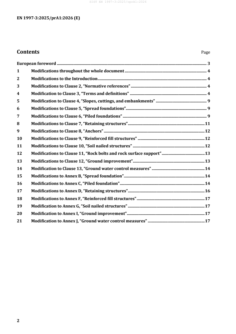
The amendment is organized as changes throughout the document, then clause-by-clause changes to the Introduction, Clause 2, Clause 3 and Clauses 4 to 13, followed by changes to Annexes B, C, D, F, G, I and J.
| Annex | What it covers |
|---|---|
| Annex B | Spread foundation |
| Annex C | Piled foundation |
| Annex D | Retaining structures |
| Annex F | Reinforced fill structures |
| Annex G | Soil nailed structures |
| Annex I | Ground improvement |
| Annex J | Ground water control measures |
What are the key requirements of EN 1997-3:2025/prA1?
EN 1997-3:2025/prA1 mainly updates the technical basis, definitions, symbols, figures, and design expressions used across geotechnical design. In practice, it tightens the links to the current Eurocode set and aligns the terminology used for foundations, retaining systems, anchors, ground improvement, and groundwater control.
- Updated design basis and references - The amendment replaces references to EN 1990, EN 1997-1 and EN 1997-2 with the newer referenced editions and adds EN 1990-2 for assessment of existing structures. That matters because designers need to apply the current basis of safety and the correct companion parts.
- Terminology and symbol cleanup - Clause 3 revises many definitions and symbols, including reinforcing element, facing element, design service life, and several resistance and strength symbols. In practice, this reduces ambiguity in calculations, reports, and tender documents.
- Spread foundations and piled foundations - Clauses 5 and 6 update wording for foundation movements, passive earth resistance, pile-ground and raft-ground interaction, and pile group and piled raft resistance. That affects how settlement, load transfer, and resistance checks are set out.
- Anchors and retaining structures - Clauses 7 and 8 revise partial factors, anchor force definitions, and earth pressure terms, including passive earth resistance for gravity walls. For design checking, this affects both resistance verification and the values used in limit state calculations.
- Reinforced fill and soil nailed structures - Clauses 9 and 10 refine the treatment of pull-out resistance, load transfer platforms over discrete ground improvement, maintenance, and the length beyond the failure surface where pull-out resistance is mobilized. This is important for detailing reinforcement lengths and inspection obligations.
- Rock bolts and rock surface support - Clause 11 updates figures and definitions, including the length of the anchoring part and a note that pre-stressing of rock bolt can lead to failure of the rock mass. That is a practical warning for design and installation control.
- Ground improvement and groundwater control - Clause 12 updates Class A and Class BII ground improvement wording and tables, and Clause 13 extends the scope of groundwater control measures to Clauses 4 to 12. This helps align method selection, verification, and documentation across the geotechnical works.
What terms does EN 1997-3:2025/prA1 define?
EN 1997-3:2025/prA1 revises or uses a set of technical terms that are central to geotechnical design.
- Reinforcing element - An element used in ground or engineered fill to stabilise geotechnical structures.
- Facing element - A modular structural facing element that embeds the connections for the reinforcement.
- Diffused ground improvement - Ground improvement where the improved zone is modelled with a single set of parameters.
- Design value of the maximum anchor force, E_d,SLS - The anchor force including lock-off load needed to prevent serviceability failure of the anchored structure.
- Length of the anchoring part, L_b - The length over which pull-out resistance is mobilized.
- Representative value of the unconfined compressive strength of the Class II ground improvement material, q_u,imp,rep - A strength value used for Class II ground improvement checks.
- Correlation factor taking into account the number of tests, ξ_ULS - A factor used in ultimate limit state evaluation when test data are available.
Who uses EN 1997-3:2025/prA1?
EN 1997-3:2025/prA1 is used by geotechnical engineers, structural engineers, and checking engineers who design or verify earthworks, foundations, retaining structures, anchors, soil nailed structures, rock bolts, and ground improvement works.
It is also relevant to contractors, specialist geotechnical subcontractors, testing organizations, and asset owners who need the design basis for temporary or permanent geotechnical structures, or who review calculations, methods, and acceptance documentation.
What changed in EN 1997-3:2025/prA1 from the previous edition?
EN 1997-3:2025/prA1 is a draft amendment that modifies EN 1997-3:2025. The changes stated in the document include updated references to EN 1990-1:2023+A1:2026, EN 1997-1:2024+A1:2026 and EN 1997-2:2024+A1:2026, the addition of EN 1990-2 in Clause 2, and revised wording in the Introduction.
It also revises terms, symbols, formulas, figures and tables across Clauses 4 to 13 and Annexes B, C, D, F, G, I and J, and adds a maintenance sub-clause for soil nailed structures.
Which standards are used with EN 1997-3:2025/prA1?
EN 1997-3:2025/prA1 is intended to be used with several other standards named in the document.
- EN 1990-1:2023+A1:2026 - basis of structural and geotechnical design for new structures.
- EN 1990-2 - assessment of existing structures.
- EN 1997-1:2024+A1:2026 - general rules for design and verification of geotechnical structures.
- EN 1997-2:2024+A1:2026 - determination of ground properties from ground investigations.
- EN 1992 (all parts), EN 1993 (all parts), EN 1994 (all parts), EN 1995 (all parts), EN 1996 (all parts) - structural design rules used for related material and component checks.
- EN 1993-5:2023 - referenced for service-life information in the soil nailed structures clause.
- EN 12715 - referenced for grouting methods in ground improvement.
- EN 19100 - listed in the Eurocode introduction as a new part under development.
What does the EN 1997-3:2025/prA1 document contain?
The document contains revised clauses, formulas, notes, figures, and tables rather than a full rewrite of the standard. It changes the Introduction, the normative references and the terms and definitions, then updates technical material on slopes, foundations, piles, retaining structures, anchors, reinforced fill, soil nailed structures, rock bolts, ground improvement, and groundwater control.
It also revises annex material for spread foundations, piled foundations, retaining structures, reinforced fill structures, soil nailed structures, ground improvement, and groundwater control measures. Several figures and tables are updated to reflect changed load paths, resistance factors, pile and raft interaction, and class-based ground improvement checks.
Get Certified
Connect with accredited certification bodies for this standard

DIBt (Deutsches Institut für Bautechnik)
German Institute for Building Technology.
DIN CERTCO
DIN Group product certification.
Zavod za gradbeništvo Slovenije (ZAG) - Inšpekcija
ZAG inspection body for construction products, structures, and materials.
Sponsored listings
Frequently Asked Questions
EN 1997-3:2025/prA1 is a draft published by the European Committee for Standardization (CEN). Its full title is "Eurocode 7 - Geotechnical design - Part 3: Geotechnical structures". This standard covers: 1.1 Scope of FprEN 1997-3 (1) This document provides specific rules to be applied in the design and verification of geotechnical structures. 1.2 Assumptions (1) This document is intended to be used in conjunction with EN 1990, which establishes principles and requirements for the safety, serviceability, robustness, and durability of structures, including geotechnical structures, and other construction works. NOTE Additional or amended provisions can be necessary for assessment of existing structures, see prEN 1990-2. (2) This document is intended to be used in conjunction with EN 1997-1, which provides general rules for the design and verification of geotechnical structures. (3) This document is intended to be used in conjunction with EN 1997-2, which gives provisions for determining ground properties from ground investigations. (4) This document is intended to be used in conjunction with the other Eurocodes for the design of geotechnical structures, including temporary geotechnical structures.
1.1 Scope of FprEN 1997-3 (1) This document provides specific rules to be applied in the design and verification of geotechnical structures. 1.2 Assumptions (1) This document is intended to be used in conjunction with EN 1990, which establishes principles and requirements for the safety, serviceability, robustness, and durability of structures, including geotechnical structures, and other construction works. NOTE Additional or amended provisions can be necessary for assessment of existing structures, see prEN 1990-2. (2) This document is intended to be used in conjunction with EN 1997-1, which provides general rules for the design and verification of geotechnical structures. (3) This document is intended to be used in conjunction with EN 1997-2, which gives provisions for determining ground properties from ground investigations. (4) This document is intended to be used in conjunction with the other Eurocodes for the design of geotechnical structures, including temporary geotechnical structures.
EN 1997-3:2025/prA1 is classified under the following ICS (International Classification for Standards) categories: 91.010.30 - Technical aspects; 93.020 - Earthworks. Excavations. Foundation construction. Underground works. The ICS classification helps identify the subject area and facilitates finding related standards.
EN 1997-3:2025/prA1 is available in PDF format for immediate download after purchase. The document can be added to your cart and obtained through the secure checkout process. Digital delivery ensures instant access to the complete standard document.
Standards Content (Sample)
SLOVENSKI STANDARD
01-julij-2026
Evrokod 7 - Geotehnično projektiranje - 3. del: Geotehnične konstrukcije
Eurocode 7 - Geotechnical design - Part 3: Geotechnical structures
Eurocode 7 - Entwurf, Berechnung und Bemessung in der Geotechnik - Teil 3:
Geotechnische Bauwerke
Eurocode 7 - Calcul géotechnique - Partie 3 : Constructions géotechniques
Ta slovenski standard je istoveten z: EN 1997-3:2025/prA1
ICS:
91.010.30 Tehnični vidiki Technical aspects
93.020 Zemeljska dela. Izkopavanja. Earthworks. Excavations.
Gradnja temeljev. Dela pod Foundation construction.
zemljo Underground works
2003-01.Slovenski inštitut za standardizacijo. Razmnoževanje celote ali delov tega standarda ni dovoljeno.
DRAFT
EUROPEAN STANDARD
EN 1997-3:2025
NORME EUROPÉENNE
EUROPÄISCHE NORM
prA1
June 2026
ICS 91.010.30
English Version
Eurocode 7 - Geotechnical design - Part 3: Geotechnical
structures
Eurocode 7 - Calcul géotechnique - Partie 3 : Eurocode 7 - Entwurf, Berechnung und Bemessung in
Constructions géotechniques der Geotechnik - Teil 3: Geotechnische Bauwerke
This draft amendment is submitted to CEN members for enquiry. It has been drawn up by the Technical Committee CEN/TC 250.
This draft amendment A1, if approved, will modify the European Standard EN 1997-3:2025. If this draft becomes an amendment,
CEN members are bound to comply with the CEN/CENELEC Internal Regulations which stipulate the conditions for inclusion of
this amendment into the relevant national standard without any alteration.
This draft amendment was established by CEN in three official versions (English, French, German). A version in any other
language made by translation under the responsibility of a CEN member into its own language and notified to the CEN-CENELEC
Management Centre has the same status as the official versions.
CEN members are the national standards bodies of Austria, Belgium, Bulgaria, Croatia, Cyprus, Czech Republic, Denmark, Estonia,
Finland, France, Germany, Greece, Hungary, Iceland, Ireland, Italy, Latvia, Lithuania, Luxembourg, Malta, Netherlands, Norway,
Poland, Portugal, Republic of North Macedonia, Romania, Serbia, Slovakia, Slovenia, Spain, Sweden, Switzerland, Türkiye and
United Kingdom.
Recipients of this draft are invited to submit, with their comments, notification of any relevant patent rights of which they are
aware and to provide supporting documentation.
Warning : This document is not a European Standard. It is distributed for review and comments. It is subject to change without
notice and shall not be referred to as a European Standard.
EUROPEAN COMMITTEE FOR STANDARDIZATION
COMITÉ EUROPÉEN DE NORMALISATION
EUROPÄISCHES KOMITEE FÜR NORMUNG
CEN-CENELEC Management Centre: Rue de la Science 23, B-1040 Brussels
© 2026 CEN All rights of exploitation in any form and by any means reserved Ref. No. EN 1997-3:2025/prA1:2026 E
worldwide for CEN national Members.
Contents Page
European foreword . 3
1 Modifications throughout the whole document . 4
2 Modifications to the Introduction . 4
3 Modifications to Clause 2, “Normative references” . 4
4 Modification to Clause 3, “Terms and definitions” . 4
5 Modification to Clause 4, “Slopes, cuttings, and embankments” . 9
6 Modifications to Clause 5, “Spread foundations”. 9
7 Modifications to Clause 6, “Piled foundations” . 9
8 Modifications to Clause 7, “Retaining structures” . 11
9 Modifications to Clause 8, “Anchors” . 12
10 Modifications to Clause 9, “Reinforced fill structures” . 12
11 Modifications to Clause 10, “Soil nailed structures” . 12
12 Modifications to Clause 11, “Rock bolts and rock surface support” . 13
13 Modifications to Clause 12, “Ground improvement” . 13
14 Modification to Clause 13, “Ground water control measures” . 14
15 Modifications to Annex B, “Spread foundation” . 14
16 Modifications to Annex C, “Piled foundation” . 14
17 Modifications to Annex D, “Retaining structures” . 16
18 Modifications to Annex F, “Reinforced fill structures” . 17
19 Modification to Annex G, “Soil nailed structures” . 17
20 Modification to Annex I, “Ground improvement” . 17
21 Modification to Annex J, “Ground water control measures” . 17
European foreword
This document (EN 1997-3:2025/prA1:2026) has been prepared by Technical Committee CEN/TC 250
“Structural Eurocodes”, the secretariat of which is held by BSI. CEN/TC 250 is responsible for all
Structural Eurocodes and has been assigned responsibility for structural and geotechnical design matters
by CEN.
This document is currently submitted to the CEN Enquiry.
This document will amend EN 1997-3:2025.
NOTE Some modifications are purely editorial corrections to improve the quality of the document and these will
not be tagged in the consolidated publication, as noted after the modification.
The first generation of EN Eurocodes was published between 2002 and 2007. This document forms part
of the second generation of the Eurocodes, which have been prepared under Mandate M/515 issued to
CEN by the European Commission and the European Free Trade Association.
The Eurocodes have been drafted to be used in conjunction with relevant execution, material, product
and test standards, and to identify requirements for execution, materials, products and testing that are
relied upon by the Eurocodes.
The Eurocodes recognize the responsibility of each Member State and have safeguarded their right to
determine values related to regulatory safety matters at national level through the use of National
Annexes.
1 Modifications throughout the whole document
Replace “EN 1990:2023” with “EN 1990-1:2023+A1:2026”.
Replace “EN 1990” with “EN 1990-1” except in subclauses 0.1 and 3.1.
Replace “EN 1997-1:2024” with “EN 1997-1:2024+A1:2026” .
Replace “EN 1997-2:2024” with “EN 1997-2:2024+A1:2026” .
2 Modifications to the Introduction
In 0.1, after list item ‘EN 1999, Eurocode 9’, add:
“— EN 19100 Eurocode 10 — Design of glass structures”.
Replace “— New parts are under development, e.g. Eurocode for design of structural glass”
with:
“— New parts are under development, e.g. Eurocode for design of fibre-polymer composite structures
and design of tensioned membrane structures”.
3 Modifications to Clause 2, “Normative references”
Replace the reference to “EN 1990:2023” with:
“EN 1990-1:2023+A1:2026, Eurocode — Basis of structural and geotechnical design — Part 1: New
structures”.
Add the following reference:
“EN 1990-2, Eurocode — Basis of structural and geotechnical design — Part 2: Assessment of existing
structures”.
4 Modification to Clause 3, “Terms and definitions”
In 3.1, introductory paragraph, replace “EN 1990” with “EN 1990 (all parts)” and add a reference to
“EN 1997-2” to read:
“For the purposes of this document, the terms and definitions given in EN 1990 (all parts), EN 1997-1,
EN 1997-2 and the following apply.”.
Delete the definition 3.1.1.6 secondary compression.
In 3.1.1.10 reinforcing element, at the end of the definition, replace “slopes or retaining structures” with
“ geotechnical structures” to read “ …ground or engineered fill for stabilising geotechnical structures.”.
In 3.1.1.13 facing element, replace “precast panel” with “structural facing element” to read read
“modular structural facing element embedding the connections….”.
Delete the definition 3.1.6.8 tendon bond length.
Delete the definition 3.1.6.9 tendon free length.
In 3.1.7.2 basal reinforcement to embankments, delete “networks” and add “grid of” to read ”….fills
founded on grid of inclusions, or for….”.
Under preparation. Current stage: EN 1997-1:2024/prA1:2026.
Under preparation. Current stage: EN 1997-2:2024/prA1:2026.
In 3.1.9.2 rock surface support, delete the Note 1 to entry: “Rock surface support is non-structural and
includes wire mesh and sprayed concrete”.
In 3.1.10.6 diffused ground improvement, delete the “be” to read “ground improvement where the
ground improvement zone is modelled with a single set of parameters”.
Delete the definition 3.1.10.7 structural connection.
Delete the definition 3.1.10.8 contact.
Following the above deletions, update the remaining term numbers in 3.1 accordingly.
In 3.2.1:
Delete symbol and definition “A ”
Replace symbol and definition A with: “A is the net reduced cross-sectional area of the reinforcing
0,con s,con
element, allowing for the effects of potential corrosion, at the termination or connection”.
Delete symbol and definition “A' ”
gs,d
Delete symbol and definition “A ”
r,con
Revise symbol A to read “A the reduced gross cross-sectional area of the reinforcing element at the
r r
weakest section, allowing for the effects of potential corrosion.”
Revise symbol A to read “A plan area of the foundation base not including any area where there is no
red red
positive contact pressure between the foundation and the underlying ground as a result of load
eccentricity, ground shrinkage, or any other cause”.
Delete symbol and definition “A ”
ru
Delete symbol and definition “A ”
ry
Delete symbol and definition “A' ”
sn,d
Delete symbol and definition “B ”
gi
Revise symbol B to read “B equivalent diameter of an inclusion”.
ri ri
Delete symbol and definition “C”
Delete symbol and definition “C ”
a
Delete symbol and definition “C ”
p
Delete symbol and definition “D ”
ds
Add symbol and definition “D void diameter at ground surface”.
s
Revise symbol E to read “E design value of the maximum anchor force, including the lock-off load,
d.SLS d.SLS
and sufficient to prevent the serviceability limit state of the anchored structure”.
Revise symbol (EI) to read “(EI) design value of bending (flexural) stiffness of the pile, according to the
d d
structural Eurocodes”.
Delete symbol and definition “EI” one of the entries
Delete symbol and definition “E ”
ur
Delete symbol and definition “E ”
i
Delete symbol and definition “F ”
cd,SLS
Revise symbol F to read “F design value of an action to prevent a at the serviceability limit state”.
d,SLS d,SLS
Revise symbol F to read “F design value of the action that the supporting element shall provide to
d,ULS d,ULS
prevent an ultimate limit state of the supported structure or the value of design action at the ultimate
limit state for piles”.
Revise symbol F to read “F value of design action applied to the pile group or piled raft”.
group,d group,d
Delete symbol and definition “F ”
tot,k
Revise symbol H to read “H height of the material over the geosynthetic layer”.
Delete symbol and definition “H ”
s
Delete symbol and definition “H ”
v
Delete symbol and definition “I”
Delete symbol and definition “K ”
u
Delete symbol and definition “K ”
y
Delete symbol and definition “L ”
int
Delete symbol and definition “L ”
j
Delete symbol and definition “L ”
n
Revise symbol L to read “L length of the anchoring part”.
b b
Revise symbol L to read “L length of the reinforcing element beyond the failure surface (or line of
po po
maximum tension) where pull-out resistance is mobilized”.
Delete symbol and definition “L ”
ps
Delete symbol and definition “N ”
a
Delete symbol and definition “N' ”
d
Delete symbol and definition “N ”
p
Delete symbol and definition “N ”
γu
Delete symbol and definition “P ”
o
Revise symbol R to read “R measured value of an anchor’s geotechnical resistance complying
am,αULS am,αULS
with the ultimate limit state criterion α ”.
ULS
Revise symbol R to read “R ultimate compressive resistance….”.
block block
Revise symbol R replace “columns” with “inclusion” to read “R ….net area between the inclusion mobilized
g g
at a settlement…”.
Revise symbol R delete “or pile raft” to read “R design resistance of pile group”.
group,d group,d
Revise symbol R delete “vertical” add “compressive” to read “R representative ultimate
group,rep group,rep
compressive resistance of pile group”.
Delete symbol and definition “R ”
gs,int,d
to read “R ultimate compressive resistance….” .
Revise symbol Ri i
Delete symbol and definition “R ”
k,com
Delete symbol and definition “R ”
k,ds
Delete symbol and definition “R ”
m,sn,pul
Delete symbol and definition “R ” one of the entries
t,el,rep
Revise symbol R delete “drained” in the definition to read “R bearing resistance normal to the base of a
N N
spread foundation”.
Delete symbol and definition “R ”
pd
Revise symbol R delete “rigid” in definition to read “R representative value of the total resistance
sys,rep sys,rep
of the ground improvement system with inclusions”.
Delete symbol and definition “R ”
sn,int,d
Delete symbol and definition “R ”
sn,int,d
Delete symbol and definition “S ”
t
Delete symbol and definition “Sv”
Revise symbol T to read “T design service life of the structure in years”.
Delete symbol and definition “T ”
f,j
Delete symbol and definition “T ”
gs,k
Delete symbol and definition “T ”
k,cr
Delete symbol and definition “T ”
p,j
Delete symbol and definition “T ”
s,j
Delete symbol and definition “T ”
ven
Delete symbol and definition “V ”
norm
Delete symbol and definition “W ”
s
Delete symbol and definition “Ws”
Delete symbol and definition “W ”
T
Delete symbol and definition “a ”
d
Delete symbol and definition “a ”
nom
Delete symbol and definition “b”
Delete symbol and definition “b ”
gs
Delete symbol and definition “b ”
st
Delete symbol and definition “c ”
min,dur
Revise symbol d to read “d reference horizontal spacing between the test profiles for the Model Pile
ref ref
Method”.
Delete symbol and definition “e ”
d
Delete symbol and definition “e ”
j
Delete symbol and definition “f ”
md
Delete symbol and definition “f ”
yk
Delete symbol and definition “k {P}”
n
Delete symbol and definition “k ”
sn
Revise symbol k to read “k coefficient of modified subgrade reaction”.
subgrade subgrade
”
Delete symbol and definition “ktanϕ
Delete symbol and definition “m ”
y
Revise symbol n delete “pile” in definition to read “n number and type of site-specific loads tests”.
test test
Delete symbol and definition “p ”
Delete symbol and definition “p' ”
Delete symbol and definition “p ”
ps
Delete symbol and definition “p ”
sn
Revise symbol q to read “q unit shaft resistance in the i-th geotechnical unit”
si si
Delete symbol and definition “q ”
sk
Delete symbol and definition “q ”
u,field
Revise definition for symbol “q ” definition “q characteristic value of the unconfined compressive
u,imp,k u,imp,k
strength of the Class II ground improvement material;”.
Add symbol and definition “q representative value of the unconfined compressive strength of the Class
u,imp,rep
II ground improvement material;”.
Replace “improved ground” with “the rock mass” to read “q representative value of the unconfined
u,rep
compressive strength of the rock mass”.
Delete symbol and definition “s ”
Delete symbol and definition “s ”
y
s are the grid spacings of the piles in the group”.
Add symbol and definition “sy, x
Delete “in days” to read “t time (since t )”
Delete symbol and definition “t ”
Delete symbol and definition “w ”
s
Delete “ground” to read “y transverse deflection of the pile at failure”
f
Delete symbol and definition “α ”
ds
Delete “from the edge of the foundation” to read “β inclination of the
...