

prEN 545
(Main)Ductile iron pipes, fittings, accessories and their joints for water pipelines - Requirements and test methods
- Abstract
This document specifies the requirements and associated test methods applicable to ductile iron pipes, fittings, accessories and their joints for the construction of pipelines outside buildings:
— to convey different types of water (e.g. raw water, treated water, re-used water) for all types of applications (e.g. water intended for human consumption, for fire protection, for snow making, for irrigation, for hydro-electricity etc.);
— with or without pressure;
— to be installed below or above ground.
This document is applicable to pipes, fittings and accessories which are:
— manufactured with socketed, flanged or spigot ends;
— supplied externally and internally coated;
— suitable for fluid temperatures between 0 °C and 50 °C, excluding frost;
— not intended for use in areas subject to reaction to fire regulations.
This does not preclude special arrangements for the products to be used at higher temperatures.
This document covers pipes and fittings cast by any type of foundry process or manufactured by fabrication of cast components, as well as corresponding joints and accessories, in a size range extending from DN 40 to DN 2 000, inclusive.
This document specifies requirements for materials, dimensions and tolerances, mechanical properties and standard coatings of ductile iron pipes and fittings. It also gives performance requirements for all components including joints. Joint design and gasket shapes are outside the scope of this document.
In addition, reference is made to the minimum performance requirements of couplings, flange adaptors and saddles manufactured for use with ductile iron pipes and fittings.
NOTE In this document, all pressures are relative pressures, expressed in bars (100 kPa = 1 bar).
- Status
- Not Published
- Publication Date
- 18-Jul-2027
- Technical Committee
- CEN/TC 203 - Cast iron pipes, fittings and their joints
- Drafting Committee
- CEN/TC 203/WG 9 - Revision of EN 545, EN 598 and EN 969
- Current Stage
- 4020 - Submission to enquiry - Enquiry
- Start Date
- 16-Jul-2026
- Due Date
- 06-Apr-2026
- Completion Date
- 16-Jul-2026

prEN 545 is a draft European Standard from CEN for ductile iron pipes, fittings, accessories and their joints for water pipelines outside buildings. It specifies requirements and test methods for products used to convey water with or without pressure, below or above ground, for applications such as human consumption, fire protection, irrigation, snow making and hydro-electricity.
What does prEN 545 specify?
prEN 545 covers the requirements for ductile iron pipes, fittings, accessories and their joints for water pipelines outside buildings. The document focuses on product performance, dimensions, coatings, test methods and conformity, so users can specify and verify components for real pipeline projects.
The scope applies to socketed, flanged and spigot ends, externally and internally coated products, and sizes from DN 40 to DN 2 000. It excludes use in areas subject to reaction to fire regulations and keeps joint design and gasket shapes outside its scope, while still setting performance expectations for the joints themselves.
The document is organized into:
- Clause 1 Scope
- Clause 2 Normative references
- Clause 3 Terms and definitions
- Clause 4 Technical requirements
- Clause 5 Performance requirements for joints and pipe saddles
- Clause 6 Test methods
- Clause 7 Performance test methods
- Clause 8 Tables of dimensions
- Clause 9 Evaluation of conformity
- Annexes A to H
| Annex | What it covers |
|---|---|
| Annex A | Pressures and pressure classes for components |
| Annex B | Longitudinal bending resistance of pipes |
| Annex C | Diametral stiffness of pipes |
| Annex D | Optional coatings |
| Annex E | Field of use in relation to soils |
| Annex F | Field of use in relation to water characteristics |
| Annex G | Calculation method for buried pipelines and heights of cover |
| Annex H | Cross references to related ISO standards |
What are the key requirements of prEN 545?
prEN 545 sets the product, test and conformity requirements that make ductile iron pipeline components suitable for water service. The most important points are the dimensional limits, material properties, coating and lining requirements, joint performance tests and the way pressure capability is declared.
Product range, pressure classes and declared pressures
Clause 4.1 and Annex A define the product family and the pressure basis. The standard covers pipes and fittings cast by any foundry process or made from cast components, plus the corresponding joints and accessories. Non-centrifugally cast pipes are treated as fittings.
Annex A links wall thickness and design to the pressure ratings PFA, PMA and PEA. In practice, this means the manufacturer must declare the pressure capability of the product family, and restrained joints may reduce the PFA. The note in the standard also makes clear that all pressures are relative pressures in bar.
Dimensions, tolerances and interchangeability
Clause 4.3 and Clause 8 set the dimensional rules for thickness, diameters, lengths and straightness. The document gives limit deviations for wall thickness, external diameter, internal diameter and standardized lengths, plus requirements for ovality and site cutting.
This matters because ductile iron pipeline parts must fit together reliably in the field. Installers need to know which pipes can be cut on site, what diameter tolerance the joint can accept, and whether a pipe is suitable for the intended pressure class.
Materials, coatings and linings
Clause 4.4 covers tensile properties and hardness, while Clauses 4.5 and 4.6 cover coatings and linings. The standard includes metallic zinc-based external coating with a finishing layer, cement mortar internal lining for pipes, and paint coatings for fittings and accessories.
These requirements matter because the coating system is part of the service life of the pipeline, especially underground. For the buyer or engineer, the coating and lining choice is not just cosmetic - it is part of corrosion protection and water contact performance.
Leak tightness and joint performance
Clause 4.8 requires components and their joints to be leak tight at PEA. Clause 5 then sets performance requirements for flexible joints, restrained flexible joints, flanged joints and pipe saddles.
A practical point is that the document does not only check the pipe body. It also checks whether the joint system can work under internal pressure, negative pressure, external pressure where applicable, and bending or restraint conditions.
How joints are validated
Clause 5 groups products by DN, and by PN where flanges are involved, so one representative size can be tested for each family when the same design basis applies. Flexible joints are tested for the relevant pressure conditions, restrained flexible joints must still be at least semi-flexible, and flanged joints are tested under combined internal pressure and bending moment.
For restrained flexible joints, the standard requires the joint to resist separation while still allowing some angular deflection. For flanged joints, the test simulates service loading, so the reader can use the result as evidence that the joint can remain tight under pressure and bending.
Test methods and factory control
Clause 6 describes the methods for checking pipe dimensions, straightness, tensile properties, hardness, leak tightness, coating mass or thickness, and cement mortar lining thickness. Clause 7 gives the performance tests for cement mortar lining strength, flexible joint leak tightness, flanged joint resistance, and pipe saddle leak tightness.
Clause 9 then requires initial performance testing and factory production control (FPC). In practice, this means the manufacturer needs documented procedures, product assessment and control of raw materials, equipment, in-process checks and non-conforming products.
What terms does prEN 545 define?
prEN 545 defines the main product and pressure terms used to specify and test ductile iron water pipeline components. These definitions matter because they fix the meaning of the sizes, pressure ratings and joint types used throughout the standard.
- Ductile iron - cast iron used for pipes, fittings and accessories in which graphite is substantially spheroidal.
- Pipe - a straight casting with uniform bore and socket, spigot or flanged ends, with certain special end pieces classified as fittings.
- Fitting - a casting other than a pipe that changes direction, deviation or bore in the pipeline.
- Accessory - a casting or fabrication other than a pipe or fitting, such as glands, bolts, locking rings, pipe saddles, flange adaptors and couplings.
- Flexible joint - a joint that allows significant angular deflection and slight centreline offset after installation.
- Restrained flexible joint - a flexible joint with a means to prevent separation of the assembled joint.
- Nominal size (DN) - the reference size designation used for components of the pipework system.
- Nominal pressure (PN) - the reference designation related to the pressure-bearing characteristics of a component.
- Allowable operating pressure (PFA) - the maximum hydrostatic pressure a component can withstand continuously in service.
- Allowable test pressure (PEA) - the maximum hydrostatic pressure a newly installed component can withstand for a short period to check integrity and tightness.
Who uses prEN 545?
prEN 545 is used by manufacturers of ductile iron pipes, fittings, accessories, couplings, flange adaptors and pipe saddles. It is also used by pipeline designers, water utility engineers, contractors, test laboratories, quality managers and buyers who need to define product performance and check conformity.
The standard is relevant for water supply systems outside buildings, including raw water, treated water and re-used water. It is also used in projects for human consumption water, fire protection, irrigation, snow making and hydro-electricity, where the pipeline may be buried or above ground and may operate with or without pressure.
What changed in prEN 545 from the previous edition?
prEN 545 will supersede EN 545:2010.
Which standards are used with prEN 545?
The document uses several normative references for materials, testing, joints and fasteners:
- EN 196-1 - strength testing of cement for the compressive strength test of cement mortar lining.
- EN 197-1 and EN 197-5 - cement specifications used for cement mortar linings.
- EN 681-1 - elastomeric seals for pipe joint seals.
- EN 1092-2 - cast iron flanges and their joints.
- EN 14901-1 and EN 14901-2 - organic coatings for fittings and accessories.
- EN 15655-1 and EN 15655-2 - organic linings for ductile iron pipes and fittings.
- EN ISO 4016, EN ISO 7091 and EN ISO 8673 - bolts, washers and nuts for flanged joints.
- EN ISO 6506-1 - Brinell hardness testing.
- EN ISO 6892-1 - tensile testing of metallic materials.
- EN ISO 6708 and EN 1333 - the definitions of DN and PN used in the terminology.
- EN 805 - pressure-related water supply terminology used in the pressure definitions.
Annex H also names related ISO standards that are used with ductile iron pipeline systems in adjacent areas:
- ISO 10802 - hydrostatic testing after installation
- ISO 13470 - trenchless applications
- ISO 21051 - construction and installation
- ISO 9349 - thermal preinsulated products
- ISO 16134 - earthquake-resistant and subsidence-resistant design
- ISO 21052 - calculation rules for restrained joint lengths
- ISO 21053 - life cycle analysis and recycling
What does the prEN 545 document contain?
prEN 545 contains a full set of tables, test methods and annex formulas rather than only general product statements. Clause 8 provides the dimensional tables for socket and spigot pipes, flanged pipes, fittings and tees, including large-DN fittings up to DN 2 000.
Clause 6 and Clause 7 describe the practical checks used in production and type testing, including wall thickness, diameters, length, straightness, tensile testing, hardness, coating thickness, cement mortar lining thickness, leak tightness and joint resistance. The document also includes a figure-based arrangement for flanged joint testing and pipe saddle testing.
The annexes add engineering data for pressure classes, bending resistance, diametral stiffness, optional coatings, soil suitability, water chemistry suitability and buried-pipeline cover calculations. Annex A is especially important because it ties declared pressure capability to component class, while Annex G supports design checks for buried installation.
Relations
- Effective Date
- 18-Jan-2023
Get Certified
Connect with accredited certification bodies for this standard

Institut za varilstvo d.o.o. (Welding Institute)
Slovenia's leading welding institute since 1952. ISO 3834, EN 1090, pressure equipment certification, NDT personnel, welder qualification. Only IIW Au
Sponsored listings
Frequently Asked Questions
prEN 545 is a draft published by the European Committee for Standardization (CEN). Its full title is "Ductile iron pipes, fittings, accessories and their joints for water pipelines - Requirements and test methods". This standard covers: This document specifies the requirements and associated test methods applicable to ductile iron pipes, fittings, accessories and their joints for the construction of pipelines outside buildings: — to convey different types of water (e.g. raw water, treated water, re-used water) for all types of applications (e.g. water intended for human consumption, for fire protection, for snow making, for irrigation, for hydro-electricity etc.); — with or without pressure; — to be installed below or above ground. This document is applicable to pipes, fittings and accessories which are: — manufactured with socketed, flanged or spigot ends; — supplied externally and internally coated; — suitable for fluid temperatures between 0 °C and 50 °C, excluding frost; — not intended for use in areas subject to reaction to fire regulations. This does not preclude special arrangements for the products to be used at higher temperatures. This document covers pipes and fittings cast by any type of foundry process or manufactured by fabrication of cast components, as well as corresponding joints and accessories, in a size range extending from DN 40 to DN 2 000, inclusive. This document specifies requirements for materials, dimensions and tolerances, mechanical properties and standard coatings of ductile iron pipes and fittings. It also gives performance requirements for all components including joints. Joint design and gasket shapes are outside the scope of this document. In addition, reference is made to the minimum performance requirements of couplings, flange adaptors and saddles manufactured for use with ductile iron pipes and fittings. NOTE In this document, all pressures are relative pressures, expressed in bars (100 kPa = 1 bar).
This document specifies the requirements and associated test methods applicable to ductile iron pipes, fittings, accessories and their joints for the construction of pipelines outside buildings: — to convey different types of water (e.g. raw water, treated water, re-used water) for all types of applications (e.g. water intended for human consumption, for fire protection, for snow making, for irrigation, for hydro-electricity etc.); — with or without pressure; — to be installed below or above ground. This document is applicable to pipes, fittings and accessories which are: — manufactured with socketed, flanged or spigot ends; — supplied externally and internally coated; — suitable for fluid temperatures between 0 °C and 50 °C, excluding frost; — not intended for use in areas subject to reaction to fire regulations. This does not preclude special arrangements for the products to be used at higher temperatures. This document covers pipes and fittings cast by any type of foundry process or manufactured by fabrication of cast components, as well as corresponding joints and accessories, in a size range extending from DN 40 to DN 2 000, inclusive. This document specifies requirements for materials, dimensions and tolerances, mechanical properties and standard coatings of ductile iron pipes and fittings. It also gives performance requirements for all components including joints. Joint design and gasket shapes are outside the scope of this document. In addition, reference is made to the minimum performance requirements of couplings, flange adaptors and saddles manufactured for use with ductile iron pipes and fittings. NOTE In this document, all pressures are relative pressures, expressed in bars (100 kPa = 1 bar).
prEN 545 is classified under the following ICS (International Classification for Standards) categories: 23.040.03 - Pipeline and its parts for external water conveyance systems; 23.040.10 - Iron and steel pipes; 23.040.40 - Metal fittings. The ICS classification helps identify the subject area and facilitates finding related standards.
prEN 545 has the following relationships with other standards: It is inter standard links to EN 545:2010. Understanding these relationships helps ensure you are using the most current and applicable version of the standard.
prEN 545 is available in PDF format for immediate download after purchase. The document can be added to your cart and obtained through the secure checkout process. Digital delivery ensures instant access to the complete standard document.
Standards Content (Sample)
SLOVENSKI STANDARD
01-julij-2026
Cevi, fitingi, pribor in spoji iz duktilne železove litine za vodovodno omrežje -
Zahteve in preskusne metode
Ductile iron pipes, fittings, accessories and their joints for water pipelines - Requirements
and test methods
Rohre, Formstücke, Zubehörteile aus duktilem Gusseisen und ihre Verbindungen für
Wasserleitungen - Anforderungen und Prüfverfahren
Tuyaux, raccords et accessoires en fonte ductile et leurs assemblages pour
canalisations d'eau - Prescriptions et méthodes d'essai
Ta slovenski standard je istoveten z: prEN 545
ICS:
23.040.10 Železne in jeklene cevi Iron and steel pipes
23.040.40 Kovinski fitingi Metal fittings
91.140.60 Sistemi za oskrbo z vodo Water supply systems
2003-01.Slovenski inštitut za standardizacijo. Razmnoževanje celote ali delov tega standarda ni dovoljeno.
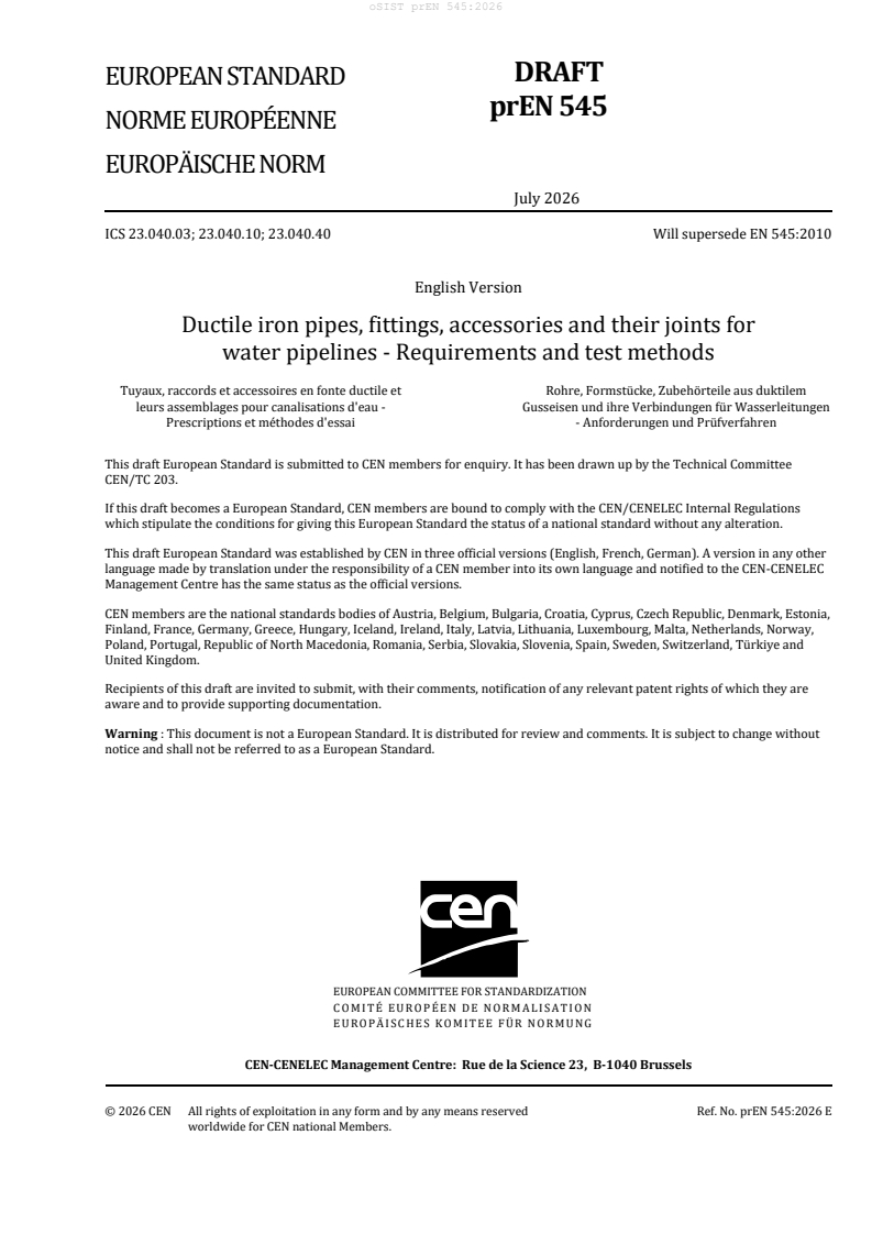
DRAFT
EUROPEAN STANDARD
NORME EUROPÉENNE
EUROPÄISCHE NORM
July 2026
ICS 23.040.03; 23.040.10; 23.040.40 Will supersede EN 545:2010
English Version
Ductile iron pipes, fittings, accessories and their joints for
water pipelines - Requirements and test methods
Tuyaux, raccords et accessoires en fonte ductile et Rohre, Formstücke, Zubehörteile aus duktilem
leurs assemblages pour canalisations d'eau - Gusseisen und ihre Verbindungen für Wasserleitungen
Prescriptions et méthodes d'essai - Anforderungen und Prüfverfahren
This draft European Standard is submitted to CEN members for enquiry. It has been drawn up by the Technical Committee
CEN/TC 203.
If this draft becomes a European Standard, CEN members are bound to comply with the CEN/CENELEC Internal Regulations
which stipulate the conditions for giving this European Standard the status of a national standard without any alteration.
This draft European Standard was established by CEN in three official versions (English, French, German). A version in any other
language made by translation under the responsibility of a CEN member into its own language and notified to the CEN-CENELEC
Management Centre has the same status as the official versions.
CEN members are the national standards bodies of Austria, Belgium, Bulgaria, Croatia, Cyprus, Czech Republic, Denmark, Estonia,
Finland, France, Germany, Greece, Hungary, Iceland, Ireland, Italy, Latvia, Lithuania, Luxembourg, Malta, Netherlands, Norway,
Poland, Portugal, Republic of North Macedonia, Romania, Serbia, Slovakia, Slovenia, Spain, Sweden, Switzerland, Türkiye and
United Kingdom.
Recipients of this draft are invited to submit, with their comments, notification of any relevant patent rights of which they are
aware and to provide supporting documentation.
Warning : This document is not a European Standard. It is distributed for review and comments. It is subject to change without
notice and shall not be referred to as a European Standard.
EUROPEAN COMMITTEE FOR STANDARDIZATION
COMITÉ EUROPÉEN DE NORMALISATION
EUROPÄISCHES KOMITEE FÜR NORMUNG
CEN-CENELEC Management Centre: Rue de la Science 23, B-1040 Brussels
© 2026 CEN All rights of exploitation in any form and by any means reserved Ref. No. prEN 545:2026 E
worldwide for CEN national Members.
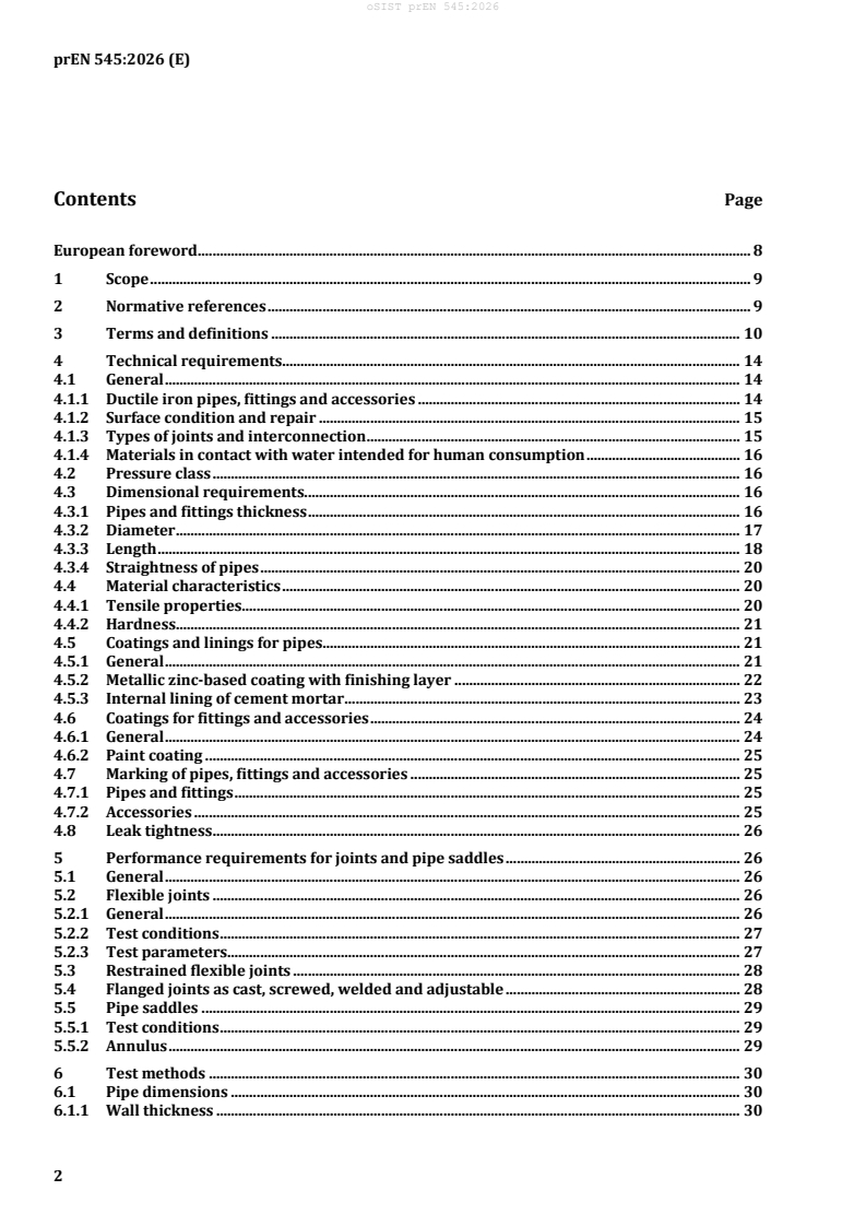
Contents Page
European foreword . 8
1 Scope . 9
2 Normative references . 9
3 Terms and definitions . 10
4 Technical requirements. 14
4.1 General . 14
4.1.1 Ductile iron pipes, fittings and accessories . 14
4.1.2 Surface condition and repair . 15
4.1.3 Types of joints and interconnection . 15
4.1.4 Materials in contact with water intended for human consumption . 16
4.2 Pressure class . 16
4.3 Dimensional requirements. 16
4.3.1 Pipes and fittings thickness . 16
4.3.2 Diameter . 17
4.3.3 Length . 18
4.3.4 Straightness of pipes . 20
4.4 Material characteristics . 20
4.4.1 Tensile properties. 20
4.4.2 Hardness . 21
4.5 Coatings and linings for pipes. 21
4.5.1 General . 21
4.5.2 Metallic zinc-based coating with finishing layer . 22
4.5.3 Internal lining of cement mortar . 23
4.6 Coatings for fittings and accessories . 24
4.6.1 General . 24
4.6.2 Paint coating . 25
4.7 Marking of pipes, fittings and accessories . 25
4.7.1 Pipes and fittings . 25
4.7.2 Accessories . 25
4.8 Leak tightness . 26
5 Performance requirements for joints and pipe saddles . 26
5.1 General . 26
5.2 Flexible joints . 26
5.2.1 General . 26
5.2.2 Test conditions . 27
5.2.3 Test parameters. 27
5.3 Restrained flexible joints . 28
5.4 Flanged joints as cast, screwed, welded and adjustable . 28
5.5 Pipe saddles . 29
5.5.1 Test conditions . 29
5.5.2 Annulus . 29
6 Test methods . 30
6.1 Pipe dimensions . 30
6.1.1 Wall thickness . 30
6.1.2 External diameter . 30
6.1.3 Internal diameter . 30
6.1.4 Length . 30
6.2 Straightness of pipes . 31
6.3 Tensile testing of ductile iron components . 31
6.3.1 Samples . 31
6.3.2 Preparation of test bar. 31
6.3.3 Apparatus and test method . 32
6.3.4 Test results . 32
6.4 Brinell hardness of ductile iron components . 33
6.5 Works leak tightness test for pipes and fittings . 33
6.5.1 General . 33
6.5.2 Centrifugally cast pipes . 33
6.5.3 Pipes not centrifugally cast, fittings and accessories . 33
6.6 Metallic zinc or alloy of zinc and aluminium mass . 33
6.7 Thickness of paint coatings . 34
6.8 Thickness of cement mortar lining . 34
7 Performance test methods . 35
7.1 Compressive strength of the cement mortar lining . 35
7.2 Leak tightness of flexible joints . 35
7.2.1 General . 35
7.2.2 Leak tightness of flexible joints to positive internal pressure . 36
7.2.3 Leak tightness of flexible joints to negative internal pressure . 37
7.2.4 Leak tightness of flexible push-in joints to positive external pressure . 37
7.2.5 Leak tightness of flexible joints to dynamic internal pressure . 37
7.3 Leak tightness and mechanical resistance of flanged joints . 38
7.4 Leak tightness and mechanical resistance of pipe saddles . 39
7.4.1 Positive internal pressure . 39
7.4.2 Negative internal pressure . 39
8 Tables of dimensions . 40
8.1 Socket and spigot pipes . 40
8.2 Flanged pipes . 42
8.3 Fittings for socketed joints . 42
8.3.1 General . 42
8.3.2 43
8.3.3 44
8.3.4 45
8.3.5 46
8.3.6 46
8.3.7 48
8.3.8 48
8.3.9 50
8.3.10 51
8.3.11 Double socket tees with flanged branch, DN 300 to DN 700 . 52
8.3.12 Double socket tees with flanged branch DN 800 to DN 2 000 . 54
8.3.13 55
8.4 Fittings for flanged joints . 56
8.4.1 General . 56
8.4.2 57
8.4.3 57
8.4.4 58
8.4.5 59
8.4.6 60
8.4.7 61
8.4.8 All flanged tees, DN 300 to DN 700 . 62
8.4.9 All flanged tees, DN 800 to DN 2000 . 63
8.4.10 64
8.4.11 66
8.4.12 66
8.4.13 67
8.4.14 68
8.4.15 69
8.4.16 69
8.4.17 70
8.4.18 71
9 Evaluation of conformity . 71
9.1 General . 71
9.2 Initial performance testing . 72
9.2.1 General . 72
9.2.2 Characteristics . 72
9.2.3 Treatment of calculated values and design . 72
9.2.4 Sampling, testing and conformity criteria . 72
9.3 Factory production control (FPC) . 73
9.3.1 General . 73
9.3.2 FPC requirements for all manufacturers . 74
9.3.3 Manufacturer-specific FPC system requirements . 75
Annex A (normative) Allowable pressures . 77
A.1 General . 77
A.2 Socket and spigot pipes (see 8.1) . 77
A.3 Fittings for socketed joints (see 8.3) . 77
A.4 Flanged pipes (see 8.2) and fittings for flanged joints (see 8.4) . 78
A.5 Accessories . 78
Annex B (informative) Longitudinal bending resistance of pipes . 79
Annex C (informative) Diametral stiffness of pipes . 80
Annex D (informative) Optional coatings . 83
D.1 Pipes . 83
D.2 Fittings and accessories . 84
Annex E (informative) Field of use in relation to the characteristics of soils. 85
E.1 Metallic zinc . 85
E.2 Alloy of zinc and aluminium with or without other metals . 85
E.3 Heavy duty coatings . 85
Annex F (informative) Field of use, water characteristics . 87
Annex G (informative) Calculation method of buried pipelines, heights of cover . 88
G.1 Calculation method . 88
G.1.1 Calculation formula . 88
G.1.2 Pressure from earth loading . 88
G.1.3 Pressure from traffic loading . 89
G.1.4 Bedding factor, K . 89
G.1.5 Factor of lateral pressure, f . 89
G.1.6 Modulus of soil reaction, E'. 89
G.2 Heights of cover . 90
Annex H (informative) EN and ISO Standards cross references for ductile iron pipes and
fittings . 91
Bibliography . 92
Tables
Table 1 — Limit deviations on thickness of fittings . 17
Table 2 — Limit deviation on internal diameter . 18
Table 3 — Maximum DN for limit deviations on internal diameter for pressure classes . 18
Table 4 — Standardized lengths of socket and spigot pipes . 18
Table 5 — Standardized lengths of flange pipes . 19
Table 6 — Permissible deviation on lengths of fittings . 20
Table 7 — Limit deviations on length . 20
Table 8 — Tensile properties . 21
Table 9 — Thickness of cement mortar lining . 24
Table 10 — DN groupings for performance tests . 26
Table 11 — Performance tests for joints . 27
Table 12 — Bending moments for flange joint performance tests . 29
Table 13 — Performance tests for pipe saddles . 30
Table 14 — Dimensions of test bar . 32
Table 15 — Works test pressure for pipes not centrifugally cast, fittings and accessories . 33
Table 16 — Dimensions of pipes of preferred pressure classes . 40
Table 17 — Dimensions of pipes . 41
Table 18 — Dimensions of flanged sockets . 43
Table 19 — Dimensions of flanged spigots and collars . 45
Table 20 — Dimensions of double socket 90° and 45° bends . 47
Table 21 — Dimensions of double socket 22,5)° and 11,25° bends . 49
Table 22 — Dimensions of all socket tees . 50
Table 23 — Dimensions of double socket tees with flanged branch, DN 40 to 250 . 51
Table 24 — Dimensions of double socket tees with flanged branch, DN 300 to DN 700 . 52
Table 25 — Dimensions of double socket tees with flanged branch, DN 800 to DN 2 000 . 54
Table 26 — Dimensions of double socket tapers . 55
Table 27 — Dimensions of double flanged 90° and 90° duckfoot bends . 57
Table 28 — Dimensions of double flanged 45° bends . 58
Table 29 — Dimensions of double flanged 22,5° and 11,25° bends . 60
Table 30 — Dimensions of all flanged tees, DN 40 to DN 250. 61
Table 31 — Dimensions of all flanged tees, DN 300 to DN 700 . 62
Table 32 — Dimensions of all flanged tees, DN 800 to DN 2000 . 63
Table 33 — Dimensions of double flanged tapers . 65
Table 34 — Dimensions of PN 10 and PN 16 blank flanges . 66
Table 35 — Dimensions of PN 25 and PN 40 blank flanges . 68
Table 36 — Dimensions of PN 10 and PN 16 reducing flanges . 70
Table 37 — Dimensions of PN 25 and PN 40 reducing flanges . 71
Table 38 — Number of test samples for initial performance testing . 73
Table 39 — Minimum frequency of product testing as part of FPC . 74
Table 40 — Maximum batch sizes for tensile testing . 75
Table A.1 — Fittings pressure class . 78
Table A.2 — Flanged pipe and fittings pressures . 78
Table B.1 — Longitudinal bending moment resistance of pipes . 79
Table C.1 — Diametral stiffness of pipes of preferred pressure classes . 81
Table F.1 — Field of use for cement mortar linings (not exhaustive) . 87
Table G.1 — Heights of cover for pipes of preferred pressure classes . 90
Figures
Figure 1 — Leak tightness test of joints (internal pressure) . 36
Figure 2 — Leak tightness test of joints (external pressure) . 37
Figure 3 — Strength and leak tightness test for flanged joints . 38
Figure 4 — Leak tightness test for pipe saddles . 39
Figure 5 — Socket and spigot pipes . 40
Figure 6 — Flanged sockets . 43
Figure 7 — Flanged spigots . 44
Figure 8 — Collars . 45
Figure 9 — Double socket 90° (1/4) bends . 46
Figure 10 — Double socket 45° (1/8) bends . 46
Figure 11 — Double socket 22°30′ (1/16) bends . 48
Figure 12 — Double socket 11°15′ (1/32) bends . 48
Figure 13 — All socket tees . 50
Figure 14 — Double socket tees with flanged branch . 51
Figure 15 — Double socket tapers . 55
Figure 16 — Double flanged 90° (1/4) bends . 57
Figure 17 — Double flanged duckfoot 90° (1/4) bends . 57
Figure 18 — Double flanged 45° (1/8) bends . 58
Figure 19 — Double flanged 22°30′ (1/16) bends . 59
Figure 20 — Double flanged 11°15′ (1/32) bends . 60
Figure 21 — All flanged tees . 61
Figure 22 — Double flanged tapers . 64
Figure 23 — Blank flanges PN 10 . 66
Figure 24 — Blank flanges PN 16 . 66
Figure 25 — Blank flanges PN 25 . 67
Figure 26 — Blank flanges PN 40 . 68
Figure 27 — Reducing flanges PN 10 . 69
Figure 28 — Reducing flanges PN 16 . 69
Figure 29 — Reducing flanges PN 25 . 70
Figure 30 — Reducing flanges PN 40 . 71
European foreword
This document (prEN 545:2026) has been prepared by Technical Committee CEN/TC 203 “Cast iron
pipes, fittings and their joints”, the secretariat of which is held by AFNOR.
This document ci currently submitted to the CEN Enquiry.
This document will supersede EN 545:2010.
In this document Annex A is normative and Annexes B, C, D, E, F, G and H are informative.
This standard is in conformity with the general requirements already established by CEN/TC 164 in the
field of water supply.
In respect of potential adverse effects on the quality of water intended for human consumption, caused
by the products covered by this standard:
— this standard provides no information as to whether the products may be used without restriction in
any of the member states of the EU or EFTA;
— it should be noted that, while awaiting the implementation of European criteria, existing national
regulations concerning the use and/or the characteristics of these products remain in force.
1 Scope
This document specifies the requirements and associated test methods applicable to ductile iron pipes,
fittings, accessories and their joints for the construction of pipelines outside buildings:
— to convey different types of water (e.g. raw water, treated water, re-used water) for all types of
applications (e.g. water intended for human consumption, for fire protection, for snow making, for
irrigation, for hydro-electricity etc.);
— with or without pressure;
— to be installed below or above ground.
This document is applicable to pipes, fittings and accessories which are:
— manufactured with socketed, flanged or spigot ends;
— supplied externally and internally coated;
— suitable for fluid temperatures between 0 °C and 50 °C, excluding frost;
— not intended for use in areas subject to reaction to fire regulations.
This does not preclude special arrangements for the products to be used at higher temperatures.
This document covers pipes and fittings cast by any type of foundry process or manufactured by
fabrication of cast components, as well as corresponding joints and accessories, in a size range extending
from DN 40 to DN 2 000, inclusive.
This document specifies requirements for materials, dimensions and tolerances, mechanical properties
and standard coatings of ductile iron pipes and fittings. It also gives performance requirements for all
components including joints. Joint design and gasket shapes are outside the scope of this document.
In addition, reference is made to the minimum performance requirements of couplings, flange adaptors
and saddles manufactured for use with ductile iron pipes and fittings.
NOTE In this document, all pressures are relative pressures, expressed in bars (100 kPa = 1 bar).
2 Normative references
The following referenced documents are indispensable for the application of this document. For dated
references, only the edition cited applies. For undated references, the latest edition of the referenced
document (including any amendments) applies.
EN 196-1, Methods of testing cement — Part 1: Determination of strength
EN 197-1, Cement — Part 1: Composition, specifications and conformity criteria for common cements
EN 197-5, Cement — Part 5: Portland-composite cement CEM II/C-M and Composite cement CEM VI
EN 681-1, Elastomeric seals — Material requirements for pipe joint seals used in water and drainage
applications — Part 1: Vulcanized rubber
EN 1092-2, Flanges and their joints — Circular flanges for pipes, valves, fittings and accessories, PN
designated — Part 2: Cast iron flanges
EN 14901-1, Ductile iron pipes, fittings and accessories — Requirements and test methods for organic
coatings of ductile iron fittings and accessories – Part 1: Epoxy coating (heavy duty)
EN 14901-2, Ductile iron pipes, fittings and accessories — Requirements and test methods for organic
coatings of ductile iron fittings and accessories — Part 2: Thermoplastic acid modified polyolefin coating
(TMPO)
EN 15655-1, Ductile iron pipes, fittings and accessories — Requirements and test methods for organic
linings of ductile iron pipes and fittings — Part 1: Polyurethane lining of pipes and Fittings
EN 15655-2, Ductile iron pipes, fittings and accessories — Requirements and test methods for organic
linings of ductile iron pipes and fittings — Part 2: Thermoplastic Acid Modified Polyolefin (TMPO) lining of
pipes
EN ISO 4016, Fasteners — Hexagon head bolts — Product grade C (ISO 4016)
EN ISO 6506-1, Metallic materials — Brinell hardness test — Part 1: Test method (ISO 6506-1)
EN ISO 6892-1, Metallic materials — Tensile testing — Part 1: Method of test at room temperature
EN ISO 7091, Plain washers — Normal series — Product grade C (ISO 7091)
EN ISO 8673, Fasteners — Hexagon regular nuts (style 1), with fine pitch thread (ISO 8673:2023)
3 Terms and definitions
For the purposes of this document, the following terms and definitions apply.
3.1
ductile iron
cast iron used for pipes, fittings and accessories in which graphite is present substantially in spheroidal
form
3.2
pipe
casting of uniform bore, straight in axis, having socket, spigot or flanged ends, except for flanged socket
pieces, flanged spigot pieces and collars which are classified as fittings
3.3
fitting
casting other than a pipe which allows pipeline deviation, change of direction or bore
Note 1 to entry: In addition flanged socket pieces, flanged spigot pieces and collars are also classified as fittings.
3.4
accessory
any casting/fabrication other than a pipe or fitting which is intended for use in a ductile iron pipeline
including:
— glands and bolts for mechanical flexible joints (see 3.14);
— glands, bolts and locking rings for restrained flexible joints (see 3.15);
— pipe saddles for service pipe connections;
— adjustable flanges and flanges to be welded or screwed;
— flange adaptors for use with ductile iron pipes and fittings (see 4.1.3.2);
— couplings for use with ductile iron pipes and fittings (see 4.1.3.2)
Note 1 to entry: Valves of all types are not covered by the term accessory.
Note 2 to entry: Wide tolerance flange adaptors and couplings are covered by EN 14525.
3.5
component
any product defined in 3.2 to 3.4
3.6
flange
end of a pipe, fitting or accessory extending perpendicular to its axis, with bolt holes equally spaced on a
circle
Note1 to entry: A flange can be fixed (e.g. integrally cast, screwed or welded) or adjustable; an adjustable flange
comprises a ring, in one or several parts assembled together, which bears on an end joint hub and can be freely
rotated around the barrel axis before jointing.
3.7
spigot
male end of a pipe or fitting
3.8
spigot end
maximum insertion depth of the spigot plus 50 mm
3.9
socket
female end of a component to make the connection with the spigot of the next component
3.10
gasket
sealing component of a joint
3.11
joint
connection between the ends of two components in which a gasket is used to affect a seal
3.12
flexible joint
joint which permits significant angular deflection both during and after installation and which can accept
a slight offset of the centreline
3.13
push-in flexible joint
flexible joint assembled by pushing the spigot through the gasket in the socket of the mating component
3.14
mechanical flexible joint
flexible joint in which sealing is obtained by applying pressure to the gasket by mechanical means, e.g. a
gland
3.15
restrained flexible joint
flexible joint in which a means is provided to prevent separation of the assembled joint
3.16
flanged joint
joint between two flanged ends
3.17
nominal size
DN
alphanumerical designation of size for components of a pipework system, to be used for reference
purposes, which comprises the letters DN followed by a dimensionless whole number which is indirectly
related to the physical size, in millimetres, of the bore or outside diameter of the end connections
[SOURCE: EN ISO 6708:1995]
3.18
nominal pressure
PN
alphanumerical designation related to a combination of mechanical and dimensional characteristics of a
component of a pipework system, to be used for reference purposes, which comprises the letters PN
followed by a dimensionless number
[SOURCE: EN 1333:2006]
Note 1 to entry: All components of the same nominal size DN and designated by the same PN number have
compatible mating dimensions.
3.19
leak tightness test pressure
pressure applied to a component during manufacture in order to ensure its leak tightness
3.20
allowable operating pressure
PFA
maximum hydrostatic pressure that a component is capable of withstanding continuously in service
[SOURCE: EN 805:2025]
3.21
pressure class
C
alphanumerical designation of a family of components, including their joints, relating to their operating
pressures as verified by all the performance tests described in this standard, which includes the letter C
followed by a dimensionless number equal to the maximum PFA in bars of the family of components
3.22
allowable maximum operating pressure
PMA
maximum pressure occurring from time to time, including surge, that a component is capable of
withstanding in service
[SOURCE: EN 805:2025]
3.23
allowable test pressure
PEA
maximum hydrostatic pressure that a newly installed component is capable of withstanding for a
relatively short duration, in order to insure the integrity and tightness of the pipeline
[SOURCE: EN 805:2025]
Note 1 to entry: This test pressure is different from the system test pressure (STP), which is related to the design
pressure of the pipeline and is intended to ensure its integrity and leak tightness.
3.24
diametral stiffness of a pipe
characteristic of a pipe which allows it to resist ovalization under loading when installed
3.25
performance test
proof of design test which is done once and shall be repeated after each change of design
3.26
laying length
length by which a pipeline progresses when an additional pipe or fitting is installed
Note 1 to entry: For socketed pipes and fittings the laying length L is equal to the overall length (OL)
e
minus the maximum spigot insertion depth (X) as given by the manufacturer. For flanged pipes and
fit
...