

SIST EN 18049-1:2026
(Main)Water wells - Part 1: Design
- Abstract
This document is applicable to all types of water wells, whether for public or private use, abstracting from or injecting water to the groundwater, in a variety of applications. These include potable water abstraction, industrial use, irrigation, dewatering, aquifer recharge, and geothermal applications, or for groundwater observation (see Clause 13).
This document does not apply to horizontal wells, groundwater quality monitoring wells in potentially contaminated sites, and closed loop geothermal systems.
This document defines design requirements of water wells for public and private users in accordance with groundwater protection goals. It gives guidelines for all planning steps from preliminary to final executive project design.
A sequential method for designing and dimensioning a well is specified. Based on the hydrogeological conditions and the objectives of the well, a step-by-step process for dimensioning the well is defined. This methodology includes dimensioning for the drilling, filter packs, sealings and screens. Furthermore, selection of appropriate materials, the pump and all other additional well equipment is outlined. With regard to the planning process references are provided for drilling methods, geophysical well logging, well development and pumping tests.
- Status
- Published
- Public Enquiry End Date
- 17-Apr-2024
- Publication Date
- 03-Nov-2026
- Technical Committee
- I13 - Imaginarni 13
- Current Stage
- 6060 - National Implementation/Publication (Adopted Project)
- Start Date
- 03-Nov-2026
- Due Date
- 08-Jan-2027
- Completion Date
- 04-Nov-2026

SIST EN 18049-1:2026 is the Slovenian standard for designing water wells, based on the European work in CEN/TC 451. It sets out a sequential design method for wells that abstract from or inject water into groundwater, and for groundwater observation wells, for public and private use.
The standard tells designers how to define the project objectives, assess the site and aquifer, size the well and pump, choose materials and equipment, and prepare the drilling and testing documents. It is aimed at the people who plan, specify, design and review water wells in practice.
What does SIST EN 18049-1:2026 specify?
SIST EN 18049-1:2026 specifies design requirements for all kinds of water wells, including wells for abstraction, injection and groundwater observation. It covers planning from the first project definition through to the final executive design.
The standard applies to a wide range of uses, including potable water abstraction, industrial use, irrigation, dewatering, infiltration or recharge, and geothermal applications. It does not apply to horizontal wells or closed loop geothermal systems.
The document is organized into 22 clauses. The main flow runs from project objectives and site characterization to risk assessment, yield estimation, pump selection, well dimensioning, materials, additional equipment, observation wells, drilling, drilling fluids, geophysical logging, development, pumping tests, waste management, control and maintenance, design review, and project design documents.
| Annex | What it covers |
|---|---|
| Annex A | Examples of specific requirements depending on the purpose of the well |
| Annex B | Failure mechanisms and impacts on the surrounding environment |
| Annex C | Submersible pump overall dimensions |
| Annex D | Criteria for selection of the drilling method and specification of drilling methods |
| Annex E | Terms, symbols, units and abbreviations of major logging techniques, plus recommended logging programmes |
What are the key requirements of SIST EN 18049-1:2026?
SIST EN 18049-1:2026 follows a step-by-step design logic: define the project, understand the site and aquifer, estimate yield, choose the pump, size the well, then plan drilling, development, testing and long-term operation. In practice, the standard asks the designer to make the main technical choices early and document them clearly.
Project definition, site conditions and aquifer knowledge
Clause 4 requires the location, purpose, required flowrate or water level, minimum technical life, water quality needs, interface with the above-ground installation and the project timeframe to be set out and agreed. This matters because the well design must match the actual business or operational need, not just the geology.
Clauses 5 to 7 require site conditions, geological and hydrogeological conditions, and qualitative risks to be assessed before construction starts. The design party needs information on ownership, access, environmental restrictions, underground services, natural hazards, other wells, pollution sources and groundwater-dependent ecosystems. In practice, this reduces the chance of choosing a site or design that later conflicts with access, safety, permitting or groundwater protection.
Clause 6 requires a forecast of groundwater properties such as temperature, electrical conductivity and relevant chemical parameters. It also points to the main ways of gathering the information, including maps, databases, nearby wells, authorities, exploratory boreholes, geophysical surveys and remote sensing where needed.
Clause 7 requires a structured risk analysis for construction and operation. The standard asks for failure mechanisms to be listed, their likelihood and consequences to be evaluated, and any need for extra investigation or mitigation to be stated. Annex B gives examples of failure mechanisms and possible control measures, so the designer can connect known risks such as artesian conditions, stacked aquifers or drilling-fluid interactions to practical countermeasures.
Yield, pump selection and well sizing
Clause 8 requires the target aquifer to be selected and the anticipated well yield to be estimated with enough confidence for design. The estimate should be documented with its sources, method, expected range and justified value. This matters because the expected yield drives the whole design, including screen length, borehole diameter and pump position.
Clause 9 links pump selection to yield, drawdown and pumping head. The standard requires the submersible pump diameter and position to be established from the expected abstraction rate and total pumping head, and the pump must sit below the lowest dynamic water level with enough water above it to avoid cavitation. Annex C supports this with overall pump dimensions, which helps the designer leave enough space in the casing and avoid a pump that cannot physically fit or cool properly.
Clause 10 is the core sizing section. It covers casing diameter, annular space, formation stabiliser, filter pack, annular seal, clay plug, separation filter, open area coefficient, critical entrance velocity, screen length and sump. The practical point is that the borehole, casing, screen and sealing system must work together as one hydraulic and mechanical system, not as separate parts.
Materials, equipment, observation wells and drilling
Clause 11 requires materials to be suitable for the intended use and compatible with one another. The standard says materials must not have physico-chemical effects on the water and must remain mechanically stable and durable during construction, operation, maintenance and rehabilitation. This matters for pump life, water quality and long-term sealing.
Clause 12 requires additional well equipment for safe operation and maintenance, such as risers, a water meter or flowmeter, access for stable water-level measurement, shut-off devices and pressure compensation where needed. For drinking water wells, it adds wellhead, sampling, and monitoring provisions.
Clause 13 covers observation wells. It requires the well to prevent surface water ingress, vertical flows between aquifers, and uncontrolled artesian outflow, while still allowing access for measurement and sampling. It also requires the screen to be installed in only one aquifer, with separate observation wells preferred for different aquifers. That is important for water-level monitoring and pumping tests because mixed inflows can distort the measurements.
Clause 14 requires the drilling method to fit both the purpose of the well and the site conditions, while limiting contamination transfer, drilling-fluid losses, clogging and ground movement. Clause 15 requires the drilling fluid to suit the purpose and site conditions and still allow adequate recovery of cuttings samples. Annex D supports method selection with criteria and method descriptions, including auger, cable tool, DTH and rotary drilling.
Clause 16 requires geophysical well logging to be planned and carried out as part of exploration and abstraction work. Annex E gives the logging methods, their units and their main extraneous effects, and also provides recommended logging programmes for different geological tasks.
Development, pumping test, waste, maintenance and final design review
Clause 17 requires well development to remove drilling residues, clean the intake area, improve near-well permeability and, where relevant, stimulate the aquifer. It also requires the progress of water quality and productivity to be documented during development so that the duration and stopping point can be judged from measured performance.
Clause 18 requires pumping tests to be planned as a sequence of step drawdown testing and long-duration aquifer testing, with suitable observation points, monitoring equipment and water sampling. This gives the basis for checking performance, drawdown behaviour, water quality and aquifer response.
Clause 19 requires site waste management, including a Waste Management Plan, control of cuttings, fluids, chemicals and test water, and a site log book for incidents and protective actions. Clause 20 requires a control and maintenance plan that sets the monitoring approach, inspection frequency, service actions and rehabilitation triggers.
Clause 21 requires the designer to review whether the well is likely to meet the project objectives, regulatory requirements and acceptable environmental limits, and to state the expected maintenance frequency and design life. Clause 22 requires the final project design documents to bring together the layout, geological log, well schematic, drilling programme, pumping-test programme, final equipment, waste disposal arrangements, cost breakdown, timetable and risk analysis.
What terms does SIST EN 18049-1:2026 define?
- Aquifer - a water-bearing geological layer made of permeable rock, fractures or unconsolidated materials.
- Aquitard - a geological formation with very low permeability that restricts groundwater flow.
- Filter pack (gravel pack) - coarse material placed between the borehole wall and the screen to retain the formation and improve hydraulic conditions.
- Formation stabiliser - sand or gravel placed in the annulus to support the borehole where full filtration is not needed.
- Drawdown - the decrease in groundwater level caused by pumping, measured from static to dynamic water level.
- Geophysical well logging - a group of techniques used to identify properties of the formations, aquifers and well.
- Down-the-hole hammer (DTH) - a self-rotating air-activated percussive drilling bit used in drilling.
- Supervisory Control and Data Acquisition (SCADA) - automated monitoring and control equipment used for continuous well surveillance.
Who uses SIST EN 18049-1:2026?
SIST EN 18049-1:2026 is used by well designers, hydrogeologists, drilling contractors, consultants, public utilities, private water suppliers, and project owners. It is also relevant to buyers and specifiers who need to define a water well project and compare offers on the same technical basis.
In practice, it supports tasks such as setting project requirements, choosing the drilling method, sizing the casing and screen, selecting the pump, planning logging and pumping tests, and defining maintenance and monitoring needs. It is especially relevant where groundwater protection, water quality, permitting and long-term operation all have to be considered together.
Which standards are used with SIST EN 18049-1:2026?
The normative reference named in the document is EN 14396, Fixed ladders for manholes. Clause 12 uses it for vertical ladders in larger closed access structures, so the ladder design can be matched to a recognized standard.
The document also points to the rest of the EN 18049 series. Clause 16.1 refers to Part 2 for acceptance inspections in newly drilled wells and to Part 3 for checking wells during regeneration, rehabilitation or decommissioning.
What does the SIST EN 18049-1:2026 document contain?
SIST EN 18049-1:2026 contains a structured design method, not just a list of requirements. It includes clause-by-clause background text, compliance points and supporting explanations that help the designer turn hydrogeological information into a workable well design.
The annexes add practical support. Annex A gives examples of extra requirements by well purpose, Annex B lists common failure mechanisms and their impacts, Annex C gives submersible pump dimensions, and Annex D helps with drilling method selection and method specification.
Annex E is a major technical appendix for logging work. It lists logging terms, symbols, units and abbreviations, explains the main geophysical methods, and provides recommended logging programmes for different borehole conditions and geological tasks.
The document also includes one table for observation-well screen and gravel-pack sizing, plus figures and method descriptions for borehole components and drilling equipment. For design and testing work, these parts help with choosing the right borehole geometry, selecting logging methods, planning drilling operations and preparing the pumping-test and development programme.
Relations
- Effective Date
- 04-Nov-2026
Get Certified
Connect with accredited certification bodies for this standard

Zavod za gradbeništvo Slovenije (ZAG) - Inšpekcija
ZAG inspection body for construction products, structures, and materials.
Sponsored listings
Frequently Asked Questions
SIST EN 18049-1:2026 is a standard published by the Slovenian Institute for Standardization (SIST). Its full title is "Water wells - Part 1: Design". This standard covers: This document is applicable to all types of water wells, whether for public or private use, abstracting from or injecting water to the groundwater, in a variety of applications. These include potable water abstraction, industrial use, irrigation, dewatering, aquifer recharge, and geothermal applications, or for groundwater observation (see Clause 13). This document does not apply to horizontal wells, groundwater quality monitoring wells in potentially contaminated sites, and closed loop geothermal systems. This document defines design requirements of water wells for public and private users in accordance with groundwater protection goals. It gives guidelines for all planning steps from preliminary to final executive project design. A sequential method for designing and dimensioning a well is specified. Based on the hydrogeological conditions and the objectives of the well, a step-by-step process for dimensioning the well is defined. This methodology includes dimensioning for the drilling, filter packs, sealings and screens. Furthermore, selection of appropriate materials, the pump and all other additional well equipment is outlined. With regard to the planning process references are provided for drilling methods, geophysical well logging, well development and pumping tests.
This document is applicable to all types of water wells, whether for public or private use, abstracting from or injecting water to the groundwater, in a variety of applications. These include potable water abstraction, industrial use, irrigation, dewatering, aquifer recharge, and geothermal applications, or for groundwater observation (see Clause 13). This document does not apply to horizontal wells, groundwater quality monitoring wells in potentially contaminated sites, and closed loop geothermal systems. This document defines design requirements of water wells for public and private users in accordance with groundwater protection goals. It gives guidelines for all planning steps from preliminary to final executive project design. A sequential method for designing and dimensioning a well is specified. Based on the hydrogeological conditions and the objectives of the well, a step-by-step process for dimensioning the well is defined. This methodology includes dimensioning for the drilling, filter packs, sealings and screens. Furthermore, selection of appropriate materials, the pump and all other additional well equipment is outlined. With regard to the planning process references are provided for drilling methods, geophysical well logging, well development and pumping tests.
SIST EN 18049-1:2026 is classified under the following ICS (International Classification for Standards) categories: 93.025 - External water conveyance systems. The ICS classification helps identify the subject area and facilitates finding related standards.
SIST EN 18049-1:2026 has the following relationships with other standards: It is inter standard links to SIST EN 14396:2004. Understanding these relationships helps ensure you are using the most current and applicable version of the standard.
SIST EN 18049-1:2026 is available in PDF format for immediate download after purchase. The document can be added to your cart and obtained through the secure checkout process. Digital delivery ensures instant access to the complete standard document.
Standards Content (Sample)
SLOVENSKI STANDARD
01-december-2026
Vodnjaki - 1. del: Načrtovanje
Water wells - Part 1: Design
Brunnen zur Wassergewinnung - Teil 1: Design
Forages pour l'extraction de l'eau - Partie 1 : Conception
Ta slovenski standard je istoveten z: EN 18049-1:2026
ICS:
93.025 Zunanji sistemi za prevajanje External water conveyance
vode systems
2003-01.Slovenski inštitut za standardizacijo. Razmnoževanje celote ali delov tega standarda ni dovoljeno.
EN 18049-1
EUROPEAN STANDARD
NORME EUROPÉENNE
October 2026
EUROPÄISCHE NORM
ICS 93.025
English Version
Water wells - Part 1: Design
Forages pour l'extraction de l'eau - Partie 1 : Brunnen zur Wassergewinnung - Teil 1: Design
Conception
This European Standard was approved by CEN on 2 February 2026.
CEN members are bound to comply with the CEN/CENELEC Internal Regulations which stipulate the conditions for giving this
European Standard the status of a national standard without any alteration. Up-to-date lists and bibliographical references
concerning such national standards may be obtained on application to the CEN-CENELEC Management Centre or to any CEN
member.
This European Standard exists in three official versions (English, French, German). A version in any other language made by
translation under the responsibility of a CEN member into its own language and notified to the CEN-CENELEC Management
Centre has the same status as the official versions.
CEN members are the national standards bodies of Austria, Belgium, Bulgaria, Croatia, Cyprus, Czech Republic, Denmark, Estonia,
Finland, France, Germany, Greece, Hungary, Iceland, Ireland, Italy, Latvia, Lithuania, Luxembourg, Malta, Netherlands, Norway,
Poland, Portugal, Republic of North Macedonia, Romania, Serbia, Slovakia, Slovenia, Spain, Sweden, Switzerland, Türkiye and
United Kingdom.
EUROPEAN COMMITTEE FOR STANDARDIZATION
COMITÉ EUROPÉEN DE NORMALISATION
EUROPÄISCHES KOMITEE FÜR NORMUNG
CEN-CENELEC Management Centre: Rue de la Science 23, B-1040 Brussels
© 2026 CEN All rights of exploitation in any form and by any means reserved Ref. No. EN 18049-1:2026 E
worldwide for CEN national Members.
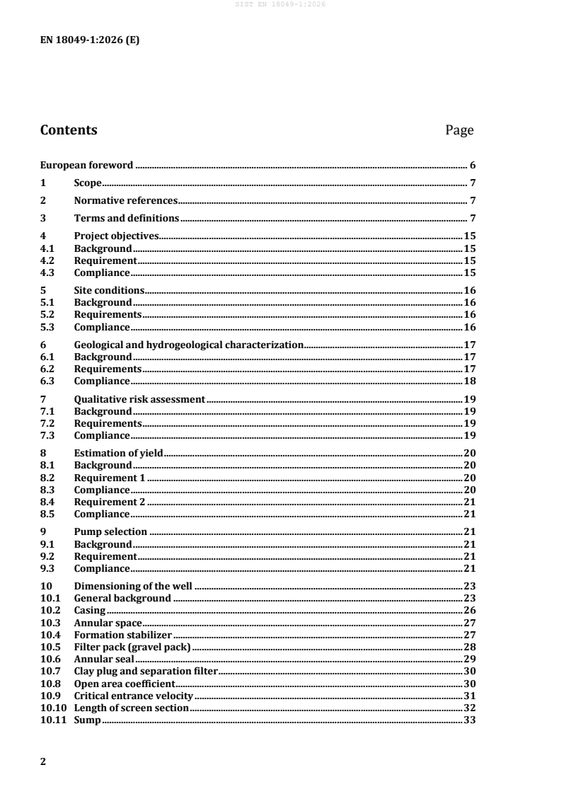
Contents Page
European foreword . 6
1 Scope . 7
2 Normative references . 7
3 Terms and definitions . 7
4 Project objectives . 15
4.1 Background . 15
4.2 Requirement . 15
4.3 Compliance . 15
5 Site conditions . 16
5.1 Background . 16
5.2 Requirements . 16
5.3 Compliance . 16
6 Geological and hydrogeological characterization . 17
6.1 Background . 17
6.2 Requirements . 17
6.3 Compliance . 18
7 Qualitative risk assessment . 19
7.1 Background . 19
7.2 Requirements . 19
7.3 Compliance . 19
8 Estimation of yield . 20
8.1 Background . 20
8.2 Requirement 1 . 20
8.3 Compliance . 20
8.4 Requirement 2 . 21
8.5 Compliance . 21
9 Pump selection . 21
9.1 Background . 21
9.2 Requirement . 21
9.3 Compliance . 21
10 Dimensioning of the well . 23
10.1 General background . 23
10.2 Casing . 26
10.3 Annular space . 27
10.4 Formation stabilizer . 27
10.5 Filter pack (gravel pack) . 28
10.6 Annular seal . 29
10.7 Clay plug and separation filter . 30
10.8 Open area coefficient . 30
10.9 Critical entrance velocity . 31
10.10 Length of screen section . 32
10.11 Sump . 33
11 Selection of materials . 33
11.1 General . 33
11.2 General requirements . 33
11.3 Filter pack. 34
11.4 Casing and screen . 35
11.5 Sealing . 37
11.6 Backfilling material . 38
12 Additional well equipment . 39
12.1 Background . 39
12.2 Requirement 1 . 40
12.3 Compliance . 40
13 Observation wells . 41
13.1 Background . 41
13.2 Requirement 1 . 42
13.3 Compliance . 42
13.4 Requirement 2 . 43
13.5 Compliance . 43
13.6 Requirement 3 . 43
13.7 Compliance . 43
14 Drilling methods . 44
14.1 Background . 44
14.2 Requirement . 44
14.3 Compliance . 44
14.4 Compliance . 45
15 Drilling fluids . 45
15.1 Background . 45
15.2 Requirements . 45
15.3 Compliance . 45
16 Geophysical well logging . 47
16.1 Background . 47
16.2 Well logging methods . 47
16.3 Quality assurance for the performance of well logging measurements . 48
16.4 Design of logging programmes . 48
17 Well Development . 50
17.1 Background . 50
17.2 Requirement 1 . 50
17.3 Requirement 2 . 50
17.4 Compliance . 51
17.5 Requirement 3 . 53
17.6 Compliance . 53
17.7 Requirement 4 . 53
17.8 Compliance . 54
17.9 Equipment . 54
17.10 Specific requirements . 54
18 Pumping test . 55
18.1 Background . 55
18.2 Minimum equipment for the well to be tested . 55
18.3 Location of observations . 55
18.4 Pumping system . 56
18.5 Monitoring equipment . 57
18.6 Performing a pumping test. 58
18.7 Water sampling and analyses . 59
19 Site waste management . 59
19.1 Background . 59
19.2 Requirement 1 . 59
19.3 Compliance . 59
19.4 Requirement 2 . 59
19.5 Compliance . 60
19.6 Requirement 3 . 60
19.7 Compliance . 60
20 Control, maintenance and monitoring . 60
20.1 Background . 60
20.2 Requirement 1 . 60
20.3 Compliance . 60
20.4 Requirement 2 . 61
20.5 Compliance . 61
21 Evaluation of the design . 62
21.1 Background . 62
21.2 Requirement . 63
21.3 Compliance . 63
22 Project design documents. 63
22.1 Background . 63
22.2 Requirement 1 . 63
22.3 Compliance . 63
22.4 Requirement 2 . 63
22.5 Compliance . 64
22.6 Requirement 3 . 64
22.7 Compliance . 64
Annex A (informative) Examples of specific requirements depending on the purpose of the
well . 65
Annex B (informative) Failure mechanisms and impacts on the surrounding environment
................................................................................................................................................................... 66
Annex C (informative) Submersible pump overall dimensions . 77
Annex D (informative) Criteria for selection of the drilling method and specification of
drilling methods . 78
D.1 Purpose of well . 78
D.2 Kind of rock . 78
D.3 Planned depth . 79
D.4 Necessity to collect reliable rock samples . 79
D.5 specification of the drilling methods . 79
Annex E (informative) Terms, symbols, units and abbreviations of major logging techniques
................................................................................................................................................................... 84
E.1 Terms, symbols, units and abbreviations of major logging methods . 84
E.2 Logging programmes for open, temporarily cased/partially cased boreholes in
unconsolidated rock – Recommended logging programmes . 86
E.3 Logging programmes for open, temporarily cased/partially cased boreholes in
consolidated rock – Recommended logging programmes . 87
Bibliography . 90
European foreword
This document (EN 18049-1:2026) has been prepared by Technical Committee CEN/TC 451 “Water wells
and borehole heat exchangers”, the secretariat of which is held by AFNOR.
This European Standard shall be given the status of a national standard, either by publication of an
identical text or by endorsement, at the latest by April 2027, and conflicting national standards shall be
withdrawn at the latest by October 2029.
Attention is drawn to the possibility that some of the elements of this document may be the subject of
patent rights. CEN shall not be held responsible for identifying any or all such patent rights.
Within its program of work, Technical Committee CEN/TC 451 requested CEN/TC 451/WG 1 “water
wells” to prepare the following standard:
EN 18049-1, Water wells — Part 1: Design.
The EN 18049 series under the main title water wells will consist of the following parts:
— Part 1: Design;
— Part 2: Construction;
— Part 3: Operation and abandoning.
Any feedback and questions on this document should be directed to the users’ national standards body.
A complete listing of these bodies can be found on the CEN website.
According to the CEN-CENELEC Internal Regulations, the national standards organisations of the
following countries are bound to implement this European Standard: Austria, Belgium, Bulgaria, Croatia,
Cyprus, Czech Republic, Denmark, Estonia, Finland, France, Germany, Greece, Hungary, Iceland, Ireland,
Italy, Latvia, Lithuania, Luxembourg, Malta, Netherlands, Norway, Poland, Portugal, Republic of North
Macedonia, Romania, Serbia, Slovakia, Slovenia, Spain, Sweden, Switzerland, Türkiye and the United
Kingdom.
1 Scope
This document is applicable to all types of water wells, whether for public or private use, abstracting from
or injecting water to the groundwater, in a variety of applications. These include potable water
abstraction, industrial use, irrigation, dewatering, aquifer recharge, and geothermal applications, or for
groundwater observation (see Clause 13).
This document does not apply to horizontal wells, groundwater quality monitoring wells in potentially
contaminated sites, and closed loop geothermal systems.
This document defines design requirements of water wells for public and private users in accordance
with groundwater protection goals. It gives guidelines for all planning steps from preliminary to final
executive project design.
A sequential method for designing and dimensioning a well is specified. Based on the hydrogeological
conditions and the objectives of the well, a step-by-step process for dimensioning the well is defined. This
methodology includes dimensioning for the drilling, filter packs, sealings and screens. Furthermore,
selection of appropriate materials, the pump and all other additional well equipment is outlined. With
regard to the planning process references are provided for drilling methods, geophysical well logging,
well development and pumping tests.
2 Normative references
The following documents are referred to in the text in such a way that some or all of their content
constitutes requirements of this document. For dated references, only the edition cited applies. For
undated references, the latest edition of the referenced document (including any amendments) applies.
EN 14396:2004, Fixed ladders for manholes
3 Terms and definitions
For the purposes of this document, the following terms and definitions apply.
ISO and IEC maintain terminology databases for use in standardization at the following addresses:
— ISO Online browsing platform: available at https://www.iso.org/obp/
— IEC Electropedia: available at https://www.electropedia.org/
3.1
abandoned well
well which is decommissioned, a term used when a well’s use is permanently discontinued or if it is in a
condition that makes it uneconomic to repair
3.2
alignment of the well
measure of the straightness of adjacent sections of a well
Note 1 to entry: Often tested by running a dummy tool into the well.
3.3
annular space (annulus)
space between a drilled hole and the well casing
3.4
aquifer
water-bearing geological layer comprising permeable rock, fractured rock or unconsolidated materials
(gravel, sand, or silt)
3.5
aquifer stimulation
type of development that is carried out to alter the formation physically to improve its hydraulic
properties
3.6
aquifer test
special case of a pumping test often using additional observation wells to obtain information about the
characteristics of an aquifer
3.7
aquitard
geologic formation having very low permeability
Note 1 to term: An aquitard with extremely low permeability can be termed aquiclude.
3.8
artesian aquifer
confined aquifer in which the piezometric surface is above the ground level
3.9
artesian well
free flowing well
wells (bore holes) that penetrate artesian aquifers
3.10
auger
machine having a rotating helical shaft for boring into the earth
3.11
bailer
cylindrical, bucket-like device with a footvalve used to collect or remove mud and rock cuttings from the
borehole
3.12
borehole
hole created by drilling into the ground
3.13
bottom hole assembly
lower portion of the drill string, which can consist of (from the bottom up) the bit, bit sub, a mud motor
(in certain cases), stabilisers, drill collars, heavyweight drill pipe, jarring devices (jar) and crossovers for
various thread forms
3.14
cable tool
group of machines for drilling by the breaking and crushing action of heavy drilling tools suspended on a
cable which are repeatedly lifted and dropped
3.15
casing
tube (usually steel or plastic) that is installed in a well to maintain the well opening and to provide a seal
3.16
cementing
specific case of grouting where only cement and water are used
3.17
centralisers
devices used to ensure that casing or riser tubes are installed centrally within the borehole
3.18
confined aquifer
aquifer whose upper and lower boundaries are low permeability layers which confine the groundwater
under greater than atmospheric pressure
3.19
core
continuous cylinder of rock, cut from the bottom of a borehole as a sample of an underground formation
3.20
cuttings
small pieces of rock or broken material derived from the drilling process, which can be used for sampling
3.21
down-the-hole hammer
DTH
self-rotating air-activated percussive drilling bit
3.22
drawdown
decrease in ground water level caused by pumping, measured as the difference between the static and
the dynamic water level at a particular time
3.23
drill bit
cutting tool used in well drilling
3.24
drilling additives
drilling fluid additives
drilling mud additives
specific components of the drilling fluid that can be used to restore the drilling mud properties or to act
in a particular way as required
3.25
drill collar
component of a drill string that provides weight on the bit for drilling
3.26
drill pipe
steel pipe used to carry and rotate the drilling tools in a well, and to permit the circulation of drilling fluid
3.27
drilling fluid
drilling mud
water or air-based fluid used in the water well drilling operation to remove cuttings from the hole, to
clean and cool the bit, to reduce friction between the drill string and the sides of the hole, and to seal the
borehole
3.28
dynamic water level
piezometric surface influenced by pumping or injection, as opposed to the static water level (3.63)
Note 1 to entry: More specifically, drawn down or raised water level, whether or not stabilized, in a pumping well
or injection structure
3.29
filter cake
suspended solids that are deposited on a porous medium during the process of filtration
3.30
free flowing well
(see artesian well)
3.31
formation
general term for the geological units surrounding the borehole
3.32
formation stabiliser
sand or gravel placed in the annulus of the well between the borehole wall and the well screen and casing
to provide temporary or long-term support for the borehole
3.33
geophysical well logging
terminology for a suite of technologies that indicate absolute or relative properties of geological
formations, aquifers and wells
3.34
filter pack
gravel pack
coarse sand, fine gravel, glass beads, or other suitable materials, that are placed between the borehole
wall and screen to retain the formation and improve the hydraulic condition around the well
3.35
grout
cement- and/or clay-based sealing material (e.g. swelling clay) used to create a sanitary seal in the
annular space to prevent crossflow between aquifers and/or contaminants from entering the well
3.36
hydraulic head loss
energy loss within a fluid system, e.g. due to friction or turbulence, as water moves from an aquifer
through the well (filter pack, screen, pump, riser pipes) to the surface
3.37
hydraulic conductivity
capacity of subsurface materials (sand, rock etc.) to allow a fluid (i.e. water) to flow through it. For an
isotropic porous medium and homogenous fluid, the volume of water that moves in unit time under a
unit hydraulic gradient through a unit area measured perpendicular to the direction of flow
3 2
Note 1 to entry: In the SI System, the units are m /s/m or m/s.
3.38
hydraulic head [m]
height above a datum plane (such as sea level) of the top of the column of water that can be supported by
the hydraulic pressure at a given point in a ground water system. For a well, the hydraulic head is equal
to the distance between the water level in the well and the datum plane
3.39
impermeable
resistant to flow of or penetration by water or other liquids
3.40
injection well
well constructed for the purpose of injecting water directly into the aquifer
3.41
infiltration well
well constructed for the purpose of allowing water to flow into the aquifer under the force of gravity
3.42
kelly
long square or hexagonal steel bar connecting the rotary table with the drill string enabling rotary
motion, while allowing the drill string to be lowered or raised during rotation
3.43
managed aquifer recharge
MAR
managed aquifer recharge (MAR) is the artificial recharge of water into aquifers for subsequent recovery
or environmental benefit
Note 1 to entry: MAR can include many techniques, such as Aquifer Storage and Recovery (ASR) for example.
3.44
monitoring well
well constructed or used for the purposes of water level or water quality data collection
Note 1 to entry: Monitoring wells are often installed to provide an early warning of contamination occurring down
gradient from a landfill or industrial facility. See also Observation wells.
3.45
observation well
well constructed in a specific location for the purpose of observing(measuring) changes in water level
Note 1 to entry: An existing well perhaps drilled for a different purpose may also be used to observe water level
changes. Observation wells are typically used for short duration data collection such as before, during and after an
aquifer test. Wells that are used to collect data on a long term basis are usually referred to as monitoring wells.
3.46
packer
device used to isolate particular portions of the aquifer in a borehole
3.47
partial penetration
when the depth of the intake portion of the well is less than the full thickness of the aquifer
3.48
piezometer
small diameter monitoring well used for water level observation (see monitoring well)
3.49
polymer mud
water based drilling fluid with polymers
3.50
porosity
property of a rock or soil containing interstices or voids, expressed as a ratio of the volume of the voids,
connected or isolated, over the total volume
Note 1 to entry Porosity can be intergranular or fissured and is responsible for storage capacity as well as
hydraulic conductivity. In hydrogeology, effective porosity (also called drainage porosity) refers to connected
interstices where water can be moving and being drained out from a sample.
3.51
production well
water well designed to meet a particular demand of groundwater
3.52
pumping test
controlled pumping with associated measurements of water level changes that are used to determine
aquifer characteristics and the hydraulic properties of wells
3.53
rig
the machine used to drill a well
3.54
rising main
drop pipe
pump column
pipe connecting the submersible pump to the wellhead
3.55
rotary table
revolving section of the drill floor that provides torque to rotate the drill string
Note 1 to entry: The rotary motion and power are transmitted through the kelly bushing and the kelly to the drill
string
3.56
saline intrusion
entry of saline water into an aquifer
3.57
saline water
salt water
water that contains high concentrations of dissolved solids, mainly sodium chloride
3.58
screen
well screen
slotted tube or wire wound screen usually made of steel or plastic material with apertures used to allow
water to enter a well while preventing sediment or rock particles from entering the well
3.59
sieve analysis
determination of the particle-size distribution of a soil, sediment, or rock by measuring the mass of the
particles that will pass through a standard set of sieves and reporting the results as the percentage
retained or passing
3.60
sinkhole
depression in the land surface caused by collapse of overlying soils or rock into pre-existing cave systems,
usually in areas of limestone geology
3.61
slurry
thin mixture of liquid, especially water, and any of several finely divided substances, such as cement or
clay particles, but capable of pumping
3.62
specific capacity
rate of discharge of a well per unit depth of drawdown. It is used as a measure of well efficiency. The ideal
for a well is high discharge and low drawdown
3 2
Note 1 to entry Units are m /s/m or m /s.
3.63
static water level
static or rest water level is the level at which water stands in a well when the water level is at equilibrium
with atmospheric pressures when it is neither under the influence of pumping nor injection
Note 1 to entry: It is a measure of the depth from the ground surface or from a known reference point to the water
level. The water level may also be measured relative to a datum such as sea level (see also, dynamic water level)
3.64
subsidence
dropping of the land surface for example as a result of over-pumping ground water. Cracks and fissures
can appear in the land
Note 1 to entry: Subsidence is usually an irreversible process.
3.65
suspended solids
soil particles that remain in suspension in water for a considerable period of time without falling to the
bottom under the force of gravity
Note 1 to entry: Such material remains in suspension due to the upward components of turbulence and currents
and/or by suspension.
3.66
test well
exploratory borehole
well used to assess and/or test the geologic and hydraulic properties of an aquifer
Note 1 to entry: A series of test wells can be drilled in order to determine the most effective location for a (much
more expensive) production well
Note 2 to entry: Test wells are usually of a smaller diameter than production wells.
3.67
top drive drilling
drilling rotary method in which the rotary motion is provided by a mechanical device (hydraulic pressure
head) located at the swivel and which moves vertically up and down the mast. It is a recent alternative to
the rotary table and kelly drive
3.68
transmissivity
rate at which groundwater can flow through an aquifer section of unit width under a unit hydraulic
gradient. It is the average hydraulic conductivity of a section of the entire aquifer at a given location
multiplied by the thickness of the producing formation
2 2
Note 1 to entry: SI-Units are m /s, sometimes expressed as m /day.
3.69
tremie pipe
pipe used to carry materials (usually grout) to a specific depth in a drilled hole. Tremie pipes are slowly
withdrawn as the grout is placed in the well
3.70
unconfined aquifer
aquifer with an upper surface as a water table whose piezometric surface is at atmospheric pressure (an
unconfined surface)
Note 1 to entry: The level of this groundwater can fluctuate, creating a saturated zone and an unsaturated zone
3.71
uniformity coefficient
d /d
60 10
ratio used to characterise a sediment using a plotted grain-size distribution curve, derived from sieving.
It is the 60% passing size (d ) divided by the 10% passing size (d )
60 10
3.72
verticality
deviation from an imaginary vertical line from the ground surface to the centre of the earth
Note 1 to entry: Usually measured in meters or centimeters.
3.73
water table
surface of a body of unconfined groundwater at which the pressure is equal to that of the atmosphere.
The static water level in a well in an unconfined aquifer
3.74
well development
application of techniques after and during the drilling process that bring the well to its maximum yield
capacity and achieve maximum well efficiency
3.75
well yield
volume of water discharged from a well in SI-Units m /s, often expressed in litres per second (l/s)
3.76
wellhead
equipment/installation used to maintain surface control of a well and prevent ingress of contamination
4 Project objectives
4.1 Background
Before starting the design of a well or well field, there needs to be an agreement between the
commissioning party and the designing party with respect to the objectives of the project.
These objectives form a framework for the entire design process, including the evaluation of the design
at the end of the design process to check whether the design meets the project objectives (as explained
in Clause 21) and the construction of the work. Secondly, the requirements form the basis of a contract
between the commissioning party and the designing party. Thus, they also serve as protection for the
customer, especially those that are not very familiar with the design of wells. Finally, the requirements
may also be used for communication with third parties who depend on the design of the well. For
example, the well discharge may be the important input for a company that is responsible for the
transmission of pumped water above ground surface.
4.2 Requirement
Identification of the location and objectives of the well as well as for the timeframe of the project.
4.3 Compliance
These following aspects shall be formulated in a document, such as a specification sheet or tender
document. Both design and commissioning party shall go through the document and agree consensually
on it.
— The location of the well. This shall either be defined in the form of georeferenced discrete point or as
an area for the project defined as a polygon of georeferenced points.
— The purpose of the well: for pumping, injection, infiltration, or as an observation well.
— The required flowrate and/or required water level. This shall be defined as a discrete number or as
a range.
— The theoretical minimum technical life span for the well.
— The minimum desired raw water quality properties of the abstracted water. These shall be in line
with the purpose of the well, the local regulations and other requirements of the commissioning
party.
— Interface with the above-ground installation. For example, the water pressure and pipe diameter at
the wellhead.
— Check if additional requirements arise from an existing legal framework
— Check if there are additional requirements, depending on the purpose of the well (see examples in
Annex A).
— A concrete time schedule or at least a timeframe. The time schedule shall at least indicate when the
wells shall be drilled and when they shall be operational, and address both the dimension and
complexity of the project.
5 Site conditions
5.1 Background
Encountering unanticipated site conditions leads to i
...