

SIST-TS CEN/TS 18182:2026
(Main)Light and lighting - Assessment of obtrusive electrical light in outdoor spaces
- Abstract
This document specifies calculation and verification methods for evaluating the spill light coming from the electric light sources of lighting installations in public and non-public outdoor areas, in the following application fields:
- lighting installations in outdoor workplaces (ref. EN 12464-2);
- road lighting installations (ref. CEN/TR 13201-1, EN 13201 series);
- lighting installations for outdoor sports fields and areas (ref. EN 12193);
- monument and architectural lighting installations;
- lighting installations for the outdoor areas of residential buildings;
- lighting installations for the outdoor areas of parks and gardens.
This document also considers luminous signs and luminous advertising installations in outdoor areas and the light emission from illuminated environments covered by translucent surfaces.
With the exception of lighting installations within premises located and designed for observation from exterior observers light emitted from windows, skylights and shop windows are excluded.
The calculation methods described are intended as an integral part of the lighting design and are suitable for evaluating consistency with any regulatory conditions.
Due to the complexity of the phenomena and the numerous variables, this document does not consider the influence of atmospheric conditions in evaluating obtrusive light.
This document does not apply to lighting installations for tunnels and underpasses and to all signalling devices such as traffic lights, active road signs and the like, or to vehicle headlamps.
This document additionally considers the spectral composition of the light concerned, as well as the room brightening at building openings not intentionally lit in the above application areas and any glare effects from these.
- Status
- Published
- Publication Date
- 09-Nov-2026
- Technical Committee
- STV - Steklo, svetloba in razsvetljava v gradbeništvu
- Current Stage
- 6060 - National Implementation/Publication (Adopted Project)
- Start Date
- 30-Oct-2026
- Due Date
- 04-Jan-2027
- Completion Date
- 10-Nov-2026

Relations
- Refers
SIST EN 12464-2:2025 - Light and lighting - Lighting of work places - Part 2: Outdoor work places - Effective Date
- 04-Nov-2026
- Effective Date
- 04-Nov-2026
- Effective Date
- 04-Nov-2026
- Effective Date
- 04-Nov-2026
- Effective Date
- 28-Jan-2026
Get Certified
Connect with accredited certification bodies for this standard

DIBt (Deutsches Institut für Bautechnik)
German Institute for Building Technology.

DIN CERTCO
DIN Group product certification.

Zavod za gradbeništvo Slovenije (ZAG) - Inšpekcija
ZAG inspection body for construction products, structures, and materials.
Sponsored listings
Frequently Asked Questions
SIST-TS CEN/TS 18182:2026 is a technical specification published by the Slovenian Institute for Standardization (SIST). Its full title is "Light and lighting - Assessment of obtrusive electrical light in outdoor spaces". This standard covers: This document specifies calculation and verification methods for evaluating the spill light coming from the electric light sources of lighting installations in public and non-public outdoor areas, in the following application fields: - lighting installations in outdoor workplaces (ref. EN 12464-2); - road lighting installations (ref. CEN/TR 13201-1, EN 13201 series); - lighting installations for outdoor sports fields and areas (ref. EN 12193); - monument and architectural lighting installations; - lighting installations for the outdoor areas of residential buildings; - lighting installations for the outdoor areas of parks and gardens. This document also considers luminous signs and luminous advertising installations in outdoor areas and the light emission from illuminated environments covered by translucent surfaces. With the exception of lighting installations within premises located and designed for observation from exterior observers light emitted from windows, skylights and shop windows are excluded. The calculation methods described are intended as an integral part of the lighting design and are suitable for evaluating consistency with any regulatory conditions. Due to the complexity of the phenomena and the numerous variables, this document does not consider the influence of atmospheric conditions in evaluating obtrusive light. This document does not apply to lighting installations for tunnels and underpasses and to all signalling devices such as traffic lights, active road signs and the like, or to vehicle headlamps. This document additionally considers the spectral composition of the light concerned, as well as the room brightening at building openings not intentionally lit in the above application areas and any glare effects from these.
This document specifies calculation and verification methods for evaluating the spill light coming from the electric light sources of lighting installations in public and non-public outdoor areas, in the following application fields: - lighting installations in outdoor workplaces (ref. EN 12464-2); - road lighting installations (ref. CEN/TR 13201-1, EN 13201 series); - lighting installations for outdoor sports fields and areas (ref. EN 12193); - monument and architectural lighting installations; - lighting installations for the outdoor areas of residential buildings; - lighting installations for the outdoor areas of parks and gardens. This document also considers luminous signs and luminous advertising installations in outdoor areas and the light emission from illuminated environments covered by translucent surfaces. With the exception of lighting installations within premises located and designed for observation from exterior observers light emitted from windows, skylights and shop windows are excluded. The calculation methods described are intended as an integral part of the lighting design and are suitable for evaluating consistency with any regulatory conditions. Due to the complexity of the phenomena and the numerous variables, this document does not consider the influence of atmospheric conditions in evaluating obtrusive light. This document does not apply to lighting installations for tunnels and underpasses and to all signalling devices such as traffic lights, active road signs and the like, or to vehicle headlamps. This document additionally considers the spectral composition of the light concerned, as well as the room brightening at building openings not intentionally lit in the above application areas and any glare effects from these.
SIST-TS CEN/TS 18182:2026 is classified under the following ICS (International Classification for Standards) categories: 91.160.20 - Exterior building lighting; 93.080.40 - Street lighting and related equipment. The ICS classification helps identify the subject area and facilitates finding related standards.
SIST-TS CEN/TS 18182:2026 has the following relationships with other standards: It is inter standard links to SIST EN 12464-2:2025, SIST EN 13201-3:2016, SIST EN 12665:2024, SIST EN 13201-5:2016, SIST EN ISO 16484-1:2024. Understanding these relationships helps ensure you are using the most current and applicable version of the standard.
SIST-TS CEN/TS 18182:2026 is available in PDF format for immediate download after purchase. The document can be added to your cart and obtained through the secure checkout process. Digital delivery ensures instant access to the complete standard document.
Standards Content (Sample)
SLOVENSKI STANDARD
01-december-2026
Svetloba in razsvetljava – Ocenjevanje moteče električne svetlobe v zunanjih
prostorih
Light and lighting - Assessment of obtrusive electrical light in outdoor spaces
Licht und Beleuchtung - Beurteilung von störendem elektrischem Licht im Außenbereich
Lumière et éclairage - Évaluation de la lumière électrique gênante dans les espaces
extérieurs
Ta slovenski standard je istoveten z: CEN/TS 18182:2026
ICS:
91.160.20 Zunanja razsvetljava stavb Exterior building lighting
93.080.40 Cestna razsvetljava in Street lighting and related
pripadajoča oprema equipment
2003-01.Slovenski inštitut za standardizacijo. Razmnoževanje celote ali delov tega standarda ni dovoljeno.
CEN/TS 18182
TECHNICAL SPECIFICATION
SPÉCIFICATION TECHNIQUE
October 2026
TECHNISCHE SPEZIFIKATION
ICS 91.160.20
English Version
Light and lighting - Assessment of obtrusive electrical light
in outdoor spaces
Lumière et éclairage - Évaluation de la lumière Licht und Beleuchtung - Beurteilung von störendem
électrique gênante dans les espaces extérieurs elektrischem Licht im Außenbereich
This Technical Specification (CEN/TS) was approved by CEN on 14 September 2026 for provisional application.
The period of validity of this CEN/TS is limited initially to three years. After two years the members of CEN will be requested to
submit their comments, particularly on the question whether the CEN/TS can be converted into a European Standard.
CEN members are required to announce the existence of this CEN/TS in the same way as for an EN and to make the CEN/TS
available promptly at national level in an appropriate form. It is permissible to keep conflicting national standards in force (in
parallel to the CEN/TS) until the final decision about the possible conversion of the CEN/TS into an EN is reached.
CEN members are the national standards bodies of Austria, Belgium, Bulgaria, Croatia, Cyprus, Czech Republic, Denmark, Estonia,
Finland, France, Germany, Greece, Hungary, Iceland, Ireland, Italy, Latvia, Lithuania, Luxembourg, Malta, Netherlands, Norway,
Poland, Portugal, Republic of North Macedonia, Romania, Serbia, Slovakia, Slovenia, Spain, Sweden, Switzerland, Türkiye and
United Kingdom.
EUROPEAN COMMITTEE FOR STANDARDIZATION
COMITÉ EUROPÉEN DE NORMALISATION
EUROPÄISCHES KOMITEE FÜR NORMUNG
CEN-CENELEC Management Centre: Rue de la Science 23, B-1040 Brussels
© 2026 CEN All rights of exploitation in any form and by any means reserved Ref. No. CEN/TS 18182:2026 E
worldwide for CEN national Members.
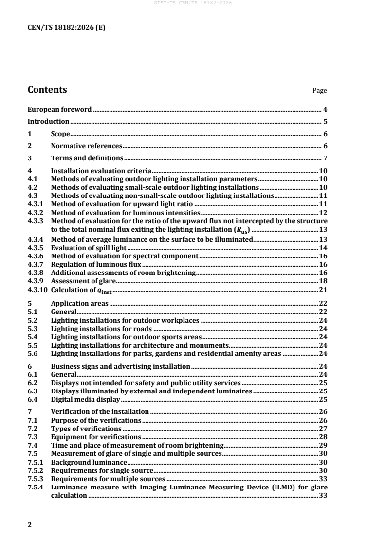
Contents Page
European foreword . 4
Introduction . 5
1 Scope . 6
2 Normative references . 6
3 Terms and definitions . 7
4 Installation evaluation criteria . 10
4.1 Methods of evaluating outdoor lighting installation parameters . 10
4.2 Methods of evaluating small-scale outdoor lighting installations . 10
4.3 Methods of evaluating non-small-scale outdoor lighting installations . 11
4.3.1 Method of evaluation for upward light ratio . 11
4.3.2 Method of evaluation for luminous intensities . 12
4.3.3 Method of evaluation for the ratio of the upward flux not intercepted by the structure
to the total nominal flux exiting the lighting installation (R ) . 13
us
4.3.4 Method of average luminance on the surface to be illuminated . 13
4.3.5 Evaluation of spill light . 14
4.3.6 Method of evaluation for spectral component . 16
4.3.7 Regulation of luminous flux . 16
4.3.8 Additional assessments of room brightening . 16
4.3.9 Assessment of glare . 18
4.3.10 Calculation of q . 21
inst
5 Application areas . 22
5.1 General. 22
5.2 Lighting installations for outdoor workplaces . 24
5.3 Lighting installations for roads . 24
5.4 Lighting installations for outdoor sports areas . 24
5.5 Lighting installations for architecture and monuments. 24
5.6 Lighting installations for parks, gardens and residential amenity areas . 24
6 Business signs and advertising installation . 24
6.1 General. 24
6.2 Displays not intended for safety and public utility services . 25
6.3 Displays illuminated by external and independent luminaires . 25
6.4 Digital media display . 25
7 Verification of the installation . 26
7.1 Purpose of the verifications . 26
7.2 Types of verifications . 27
7.3 Equipment for verifications . 28
7.4 Time and place of measurement of room brightening . 29
7.5 Measurement of glare of single and multiple sources . 30
7.5.1 Background luminance . 30
7.5.2 Requirements for single source . 30
7.5.3 Requirements for multiple sources . 33
7.5.4 Luminance measure with Imaging Luminance Measuring Device (ILMD) for glare
calculation . 33
Annex A (normative) Calculation of R with the virtual container (Black Box - BB model) . 34
us
A.1 General . 34
A.2 Geometry of the virtual container (BB) . 34
A.3 Conventions for calculation . 34
A.4 Calculation procedure. 35
Annex B (normative) Determination of spill light in the upper half-space . 38
B.1 Method 1: Photometry in constant steps with intervals of 5° between the C half-planes
and 2,5° for the angles γ - values of the partial solid angles for calculation of the spill
light in the upper half-space Φ . . 38
Δγ,i
B.2 Method 2: Variable step photometry . 40
Annex C (informative) Calculation grid . 41
C.1 Grid for calculating spill light (4.3.5.1) . 41
C.2 Grid for all other applications . 41
Annex D (informative) Verification and characterization of the lighting installation . 42
D.1 Preliminary documentary check for lighting installations . 42
D.2 Preliminary documentary check for business signs and advertising installations . 42
D.3 On-site geometrical verification . 43
D.4 On-site photometric verification . 44
D.5 Characterization . 44
D.6 Measurement taking . 46
Bibliography . 48
European foreword
This document (CEN/TS 18182:2026) has been prepared by Technical Committee CEN/TC 169 “Light
and lighting”, the secretariat of which is held by DIN.
Attention is drawn to the possibility that some of the elements of this document may be the subject of
patent rights. CEN shall not be held responsible for identifying any or all such patent rights.
Any feedback and questions on this document should be directed to the users’ national standards body.
A complete listing of these bodies can be found on the CEN website.
According to the CEN/CENELEC Internal Regulations, the national standards organisations of the
following countries are bound to announce this Technical Specification: Austria, Belgium, Bulgaria,
Croatia, Cyprus, Czech Republic, Denmark, Estonia, Finland, France, Germany, Greece, Hungary, Iceland,
Ireland, Italy, Latvia, Lithuania, Luxembourg, Malta, Netherlands, Norway, Poland, Portugal, Republic of
North Macedonia, Romania, Serbia, Slovakia, Slovenia, Spain, Sweden, Switzerland, Türkiye and the
United Kingdom.
Introduction
This document covers issues involved in limiting the spilling of electric light towards the sky and/or
beyond the surfaces to be illuminated.
Aspects attributable to the energy performance of lighting installations are not covered, as they are
already the subject of other specific CEN documents.
Reflected light is not part of the methods given in this document but might be subject to additional
considerations under specific conditions by a not yet standardized calculation method.
Since the topic is the subject of legislative activities, this document is intended to constitute a technical
reference tool, in order that all operators in the sector can act according to unified procedures.
1 Scope
This document specifies calculation and verification methods for evaluating the spill light coming from
the electric light sources of lighting installations in public and non-public outdoor areas, in the following
application fields:
— lighting installations in outdoor workplaces (ref. EN 12464-2);
— road lighting installations (ref. CEN/TR 13201-1, EN 13201 series);
— lighting installations for outdoor sports fields and areas (ref. EN 12193);
— monument and architectural lighting installations;
— lighting installations for the outdoor areas of residential buildings;
— lighting installations for the outdoor areas of parks and gardens.
This document also considers luminous signs and luminous advertising installations in outdoor areas and
the light emission from illuminated environments covered by translucent surfaces.
With the exception of lighting installations within premises located and designed for observation from
exterior observers light emitted from windows, skylights and shop windows are excluded.
The calculation methods described are intended as an integral part of the lighting design and are suitable
for evaluating consistency with any regulatory conditions.
Due to the complexity of the phenomena and the numerous variables, this document does not consider
the influence of atmospheric conditions in evaluating obtrusive light.
This document does not apply to lighting installations for tunnels and underpasses and to all signalling
devices such as traffic lights, active road signs and the like, or to vehicle headlamps.
This document additionally considers the spectral composition of the light concerned, as well as the room
brightening at building openings not intentionally lit in the above application areas and any glare effects
from these.
2 Normative references
The following documents are referred to in the text in such a way that some or all of their content
constitutes requirements of this document. for dated references, only the edition cited applies. for
undated references, the latest edition of the referenced document (including any amendments) applies.
EN 12464-2, Light and lighting — Lighting of work places — Part 2: Outdoor work places
EN 12665, Light and lighting — Basic terms and criteria for specifying lighting requirements
EN 13201-3:2015, Road lighting — Part 3: Calculation of performance
EN 13201-5:2015, Road lighting — Part 5: Energy performance indicators
ISO/CIE 19476:2014, Characterization of the performance of illuminance meters and luminance meters
CIE 150:2017, Guide on the limitation of the effects of obtrusive light from outdoor lighting installations
3 Terms and definitions
For the purposes of this document, the terms and definitions given in EN 12665 and the following apply.
ISO and IEC maintain terminology databases for use in standardization at the following addresses:
— ISO Online browsing platform: available at https://www.iso.org/obp/
— IEC Electropedia: available at https://www.electropedia.org/
3.1
upper half-space
half-space at and above 90°, passing through the photometric centre of a luminaire defined according to
EN 13032-1 or EN 13032-4 as applicable
Note 1 to entry: In the C-γ coordinate system the horizontal plane is identified by the angle γ = 90°.
3.2
lower half-space
half-space at and below 90°, passing through the photometric centre of a luminaire defined according to
EN 13032-1 or EN 13032-4 as applicable
Note 1 to entry: In the C-γ coordinate system the horizontal plane is identified by the angle γ = 90°.
3.3
design upper luminous flux
Φ
θ,ψ
luminous flux emitted in the upper half-space by a luminaire under the nominal installation conditions θ,
ψ and υ
Note 1 to entry: The design upper luminous flux can be determined using EN 13032-4:2015+A1:2019, 6.3.
Note 2 to entry: The design upper luminous flux is expressed in lumens (lm).
Note 3 to entry: See Figure 1.
Key
1 first axis
2 second axis
3 third axis
4 longitudinal axis
Figure 1 — Definition of the angles θ, ψ and υ and axes of rotation in relation to the (x, y)
coordinate system
3.4
upper spill ratio
R
us
ratio of the luminous flux emitted in the upper half-space by all luminaires and not intercepted by the
structure to the luminous flux of the same luminaires emitted in the entire space
Note 1 to entry: A number of currently available lighting design programs can directly provide parameters that are
similar to R but which are identified with symbols other than those given in this document, see Note to Clause A.4.
us
Note 2 to entry: structure includes any kind of object such as buildings, walls, trees, columns, mechanical shielding,
etc.
3.5
spill light
stray light
light emitted by a lighting installation that falls outside the boundaries of the
property or area for which the lighting installation is designed
[SOURCE: EN 12665:2024, 3.2.47]
3.6
obtrusive light
spill light which, because of quantitative or directional attributes, gives rise to annoyance, discomfort,
distraction, or a reduction in ability to see essential information such as transport signals
[SOURCE: CIE S 017:2020, 17-29-181]
3.7
small-scale outdoor lighting installation
outdoor lighting installation pertaining to a single connection point of the distributor (fiscal energy
meter) that simultaneously satisfies the following conditions:
— total luminous flux not exceeding 1800 lm emitted by the source (or any group of sources) installed
in a luminaire with replaceable source(s) or by a single luminaire with non-replaceable source(s);
— total luminous flux emitted upwards, by the set of luminaires, not exceeding 2250 lm
3.8
business sign
writing in alphanumeric characters possibly supplemented by symbols and trademarks, constructed and
supported with materials of any nature and installed in the place of business to which it refers or in the
related facilities of that business
Note 1 to entry: It can be luminous both due to its own light and due to indirect light.
3.9
illuminated advertisement
any word, letter, model, sign, placard, board, notice, awning, blind, device or representation, that is
illuminated and employed wholly or partly for the purposes of advertisement, announcement or
direction
Note 1 to entry: The definition includes any hoarding or similar structure used, or designed or adapted for use, and
anything else principally used, or designed or adapted principally for use for the display of advertisements, and
references to the display of advertisements shall be construed accordingly.
Note 2 to entry: The definition excludes anything employed as a memorial or transport/traffic signal.
Note 3 to entry: A range of modern devices for outdoor are within this definition. These include rotating poster
panels, advertisements displayed on permanently fixed blinds.
3.10
digital media display
any electronic display that emits light and is employed wholly or partly for the purpose of displaying
digital art, video or other media content
Note 1 to entry: This includes any hoarding or similar structure used, or designed or adapted for use, and anything
else principally used, or designed or adapted principally for use for the display of digital art, video or other media
content.
3.11
image luminance measuring device
ILMD
digital electronic device, equipped with a lens, a suitable photometric matching filter, a sensor made by a
matrix of detector (pixel), and calibrated for measuring the luminance distributions of the framed scene
[Source: EN 12665:2024, 3.6.9 – modified: Notes to entry omitted]
3.12
virtual container
BB
black box
mathematical model consisting of a container without reflections and a parallelepiped shape that
contains the object to be illuminated and the corresponding lighting installation
3.13
background luminance
luminance of the part of a picture, object or scene in the field of view, excluding the main figures or objects
of interest
4 Installation evaluation criteria
4.1 Methods of evaluating outdoor lighting installation parameters
For small-scale outdoor lighting installation as defined in 3.7, the method given in 4.2 shall be used to
evaluate the lighting installation. For all other outdoor installations, the methods given in 4.3 apply, as
described in Table 3.
4.2 Methods of evaluating small-scale outdoor lighting installations
4.2.1 Where national regulations or mandatory requirements do not define small-scale outdoor lighting
installation, the definition in 3.7 applies.
4.2.2 If the photometric data of the luminaires are available (e.g. luminous intensity distribution tables),
at the design stage, by means of calculation, compliance with the two conditions referred to in definition
3.7 (luminous flux emitted by the source or by any group of light sources and total luminous flux emitted
upwards by the set of luminaires) shall be verified.
NOTE It is not always mandatory to provide photometric data of luminaires sold in stores.
4.2.3 If photometric data of the sources and luminaires used are not available, both at the design stage
and during any on-site verifications, the following procedure shall be applied.
a) Estimation of luminous flux emitted by the source: the luminous flux to be considered for the
purposes of the calculation is declared on the light source(s) and/or on the commercial packaging.
b) Estimation of upward emission: calculation method simplified by specifying three categories of
luminaire with three possible fixed and predefined upward emissions (without the obligation of any
measurement):
1) For luminaires with unshielded upward light emission, i.e. recessed ground luminaires, upward
facing projectors, wall lights with upward emission only and other similar cases, the total
luminous flux emitted upwards by the individual luminaire is by convention 100 %.
2) For luminaires with downwards light emission or luminaires inclined downwards and/or
partially shielded upwards, e.g. spheres with shielding, luminaires with curved and/or inclined
glass and other similar cases, the total luminous flux emitted upward by the individual luminaire
is by convention 20 %.
3) For luminaires with only downwards light emission or luminaires fully shielded upwards, the
total luminous flux emitted upward by the individual luminaire is by convention 0 %.
4.3 Methods of evaluating non-small-scale outdoor lighting installations
4.3.1 Method of evaluation for upward light ratio
The calculation of the upward light ratio R in the installation conditions of all the luminaires involved
UL
shall be carried out considering the following orientation, tilt and rotation angles of a luminaire.
For a road lighting installation, the three orientation angles of a luminaire are specified, considering a
right-handed Cartesian coordinate system in space, identified by the axes:
— x parallel to the axis of the road;
— y transverse to the road;
— z perpendicular to the road surface and directed upwards.
For other installation types, the following angles are considered (see Figure 1):
— ν positive rotation angle about the vertical axis of the luminaire from x to y;
— θ positive tilt angle of the luminaire from y to z;
— ψ positive rotation angle of the luminaire from z to x.
Two different calculation methods are envisaged for spill light in the upper half-space of luminaires in
relation to the type of photometry with constant or variable steps, as described in Annex B. In case of θ
and ψ equal to 0, the luminous flux calculated in the Annex B is the spill light in the upper half-space; if
these angles are not equal to 0, then only B.1 can be applied by adding a correction for angles θ or ψ.
R shall be calculated separately, according to Formula (1):
UL
n
Φ
∑ u,i
i=1
R = 100 (1)
UL
n
Φ
∑ t,i
i=1
where
n is the total number of installed luminaires;
Φ is the total luminous flux emitted by the i installed luminaire;
t,i th
Φ is the luminous flux emitted by the i installed luminaire in the upper half-space in the
u,i th
installation conditions.
NOTE 1 The design specifies to which luminaires the R is referring to.
UL
NOTE 2 The calculation of R refers to a hypothetical lighting system installed in an empty space, that is, it is
UL
considering only the radiation emitted by luminaires, without considering e.g. any shielding provided by trees or
reflections from illuminated surfaces.
In the presence of screens which are not part of the original lighting installation and are capable of
effectively limiting the luminous flux emitted in the upper half-space, the R parameter shall be
us
calculated according to 4.3.3.
4.3.2 Method of evaluation for luminous intensities
4.3.2.1 General
Although the most suitable quantity to characterize the upward spill light is the luminous flux emitted by
the installation in the upper half-space (spill light), evaluated using the method described in 4.3.1, by way
of simplification it is possible to refer to the distribution of light intensities of the individual luminaire.
By this method, the luminous intensity values in directions at 90° and above with respect to the vertical
are considered, with the luminaire oriented in the installation condition.
NOTE The light intensity distribution can be absolute or relative.
4.3.2.2 Conversion from relative photometry to absolute photometry
When photometry is scaled to 1 000 lm, the following Formula (2) is applied to obtain the intensities in
absolute values:
Φ
t
II= (2)
A nf
1 000 lm
where
I is the absolute value for rated luminous intensity (unit: cd);
A
I is the relative value for rated luminous intensity referring to a luminous flux of 1 000 lm,
nf
where “nf” in subscript stands for “normalised flux” (unit: candelas per thousand lumens);
Φ for luminaires with replaceable lamp(s), it is the total luminous flux of the lamp(s); for LED
t
luminaires with non-replaceable source(s), it is the total luminous flux of the luminaire itself
(unit: lm).
NOTE Formula (2) is derived from EN 13032-4:2015+A1:2019, 6.5.3.
4.3.2.3 Conversion from absolute photometry to relative photometry
When the photometry is absolute, the following Formula (3) is applied to obtain the intensities in values
referred to 1 000 lm:
1 000 lm
II= (3)
nf A
Φ
t
where
I is the absolute value for rated luminous intensity (unit: cd);
A
I is the relative value for rated luminous intensity referring to a luminous flux of 1000 lm,
nf
where “nf” in subscript stands for “normalised flux” (unit: candelas per thousand lumens);
Φ for luminaires with replaceable lamp(s), it is the total luminous flux of the lamp(s); for LED
t
luminaires with non-replaceable source(s), it is the total luminous flux of the luminaire itself
(unit: lm).
NOTE Formula (3) originates from EN 13032-4:2015+A1:2019, 6.5.3.
4.3.3 Method of evaluation for the ratio of the upward flux not intercepted by the structure to
the total nominal flux exiting the lighting installation (R )
us
To determine the ratio of the upward flux not intercepted by the structure to the total nominal flux exiting
the lighting installation (R ), the calculation method described in Annex A shall be applied.
us
In agreement with the purchaser, it is the designer’s responsibility to use a 3D model of the object/objects
that is sufficiently accurate for the required purpose.
NOTE This method provides a more precise result as soon as the luminaires of the lighting system are
positioned in a lower mounting height than the position of the subject to be lighted.
4.3.4 Method of average luminance on the surface to be illuminated
A balanced luminance between the object and background is the parameter that allows visibility of any
surface, thus monuments or artefacts lit properly can be enjoyed and seen. Therefore, it is desirable to
limit as much as possible the light from the system to minimize obtrusive light produced by reflections.
For the purposes of this document, the average luminance of the surface shall be evaluated for new
luminaires and sources, that is, the calculation of this quantity shall be performed with a maintenance
factor equal to 1,00.
For the calculation of luminance on the illuminated surface, Lambertian surfaces are conventionally
considered; if the reflection factor of the surface is not available, reference may be made to Table 1.
The designer shall indicate in the design the reflectance values of the surfaces used for the calculation.
In the case of complex surfaces for which it is difficult to assess an average reflectance of the illuminated
surface, and which can locally result in measured luminance values higher than the designed ones, the
verification shall be performed by referring to the calculated illuminance values.
NOTE 1 A discrepancy in the measured luminance values with respect to the calculated values is normally
observed in the presence of non-Lambertian surfaces.
The Formula (4) to be used for calculating the average luminance is the following:
L
Eh⋅⋅ρ
L= (4)
π
where
is the average illuminance of the surface of the monument or object;
E
ρ is the average reflectance of the illuminated surface;
h is the coefficient of the specular component of the surface.
The reflectance values ρ for some materials commonly used for monuments and objects are listed in
Table 1.
Table 1 — Reflectance (ρ) of the most common materials (Source: CIE 150:2017, Table E.1)
Material Reflectance
ρ
Concrete medium-shade 0,3 / 0,4
Light yellow brick 0,35
Brown brick 0,30
Red brick 0,15
Pink granite 0,30
Grey granite 0,10 / 0,15
Light marble 0,5 / 0,6
Light-coloured marble 0,3
Dark marble 0,15
Light stone 0,5
Stone medium-shade 0,3
Dark stone 0,15
If the reflectance value ρ is not measured, the values indicated in Table 1 may be used.
Furthermore, h shall be explicitly indicated in the design documentation, and it is one of the following
values:
— h = 1 for a diffusing surface (Lambertian);
— h = 1,3 for a non-Lambertian surface illuminated from below;
— h = 0,7 for non-Lambertian surface illuminated from above.
NOTE 2 If the gloss or q(BRDF) of the surface is known, ASTM D523 can be consulted to determine the h factor.
4.3.5 Evaluation of spill light
4.3.5.1 General method
To prevent and improve the night-time environment, it is necessary to control spill light.
Upon completion of the design, to verify the amount of luminous flux that can enter a property adjacent
to the installation under consideration, it is necessary to calculate the illuminance on:
— a vertical computation surface on the surrounding building façade with a minimum height equal to
the height of the building;
— a vertical computation surface passing through the perimeter of the property with a minimum height
equal to the height of the highest luminous centre, or as high as necessary to capture the total flux
towards the properties, and on a horizontal computation surface, in the neighbouring property
adjacent to the border, up to 2 m wide and at a height not exceeding 0,25 m above the ground.
Limit values can be based upon average or maximum illuminance depending upon local regulations.
The surfaces determined as indicated above can also be related to specific points of interest (for example
windows, skylights, louvres, etc.).
Each calculation surface should correspond to a verification grid dimensioned as indicated in Annex C.
All calculations shall be performed using new sources (i.e. maintenance factor of 1,00).
Only direct spill light from the luminaire(s) is considered.
If there is likely to be a significant addition to the vertical illuminance as a consequence of reflected light,
the designer can assess its value using reflectance of materials as in Table 1 and the estimation should be
done by e.g. radiosity calculation software.
4.3.5.2 Specific method for functional outdoor lighting of sports facilities – verification of
intrusive light
For sports facilities for which no specific requirements of the sports federations are prescribed in terms
of vertical illuminance, the maximum vertical illuminance E is verified on specific calculation grids
v,max
located around the total area (TA) of the sports field, by calculating a percentage of the horizontal
illuminance (X ).
%
Neutral surfaces for the purpose of intrusive light, e.g. walls without windows, can be excluded from the
assessment.
The value X is verified on the vertical surface placed at a minimum distance of D around the total area
% v
(TA). Each calculation surface should correspond to a verification grid dimensioned as indicated in
Annex C. All calculations shall be carried out using new sources (i.e. maintenance factor of 1,00).
The value of D is calculated as follows:
v
For rectangular total area (TA):
Dl⋅ (5)
v,length TA
D ⋅ w (6)
v,width TA
where
l is the length of the total area;
TA
w is the width of the total area.
TA
For non-rectangular total area (TA):
Dl⋅ (7)
v,length TA
If distances calculated with these formulae are less than 10 m, D is 10 m.
v
The maximum value of vertical illuminance E calculated from a height of 1 m up to a height equal to
v,max
the installation plane of the highest luminaire that is pertinent to the verification grid, is related to the
average illuminance value of the playing area (PA), determined in the project.
E
PA
E
V,max
X = (8)
%
E
PA
=
=
=
4.3.6 Method of evaluation for spectral component
The spectral index I is an indicator that characterizes the spectral properties of light sources, indicating
Sg
the amount of emitted blue light, in comparison with the total radiance related to the spectral curve of
photopic vision.
NOTE 1 I is equivalent to the G index as in the Revision of the EU Green Public Procurement Criteria for Road
Sg
Lighting and traffic signals.
The index I shall be calculated by applying Formula (9) to the spectral distribution of the light source,
Sg
tabulated with a resolution of at least 5 nm as a function of the relative photopic vision curve V(λ):
λ
E λ ⋅∆λ
( ) ( )
∑
λ
I =−⋅2,5 log (9)
Sg
λ
EVλ ⋅⋅λ ∆λ
( ) ( ) ( )
∑
λ
where
E(λ) is the radiant intensity for the specific wavelength;
λ is equal to 380 nm;
is equal to 500 nm;
λ
λ is equal to 780 nm;
V(λ) is the spectral luminous efficiency for photopic vision; and
Δ(λ) is the wavelength range.
NOTE 2 If necessary, additional spectral indices can be used for particular needs (in this regard, see
CIE S 026/E:2018, Galadi-Enríquez, D. (2018) and Longcore (2018)).
4.3.7 Regulation of luminous flux
During switch-on hours, lighting installations for buildings, monuments and objects, as well as for areas
not subject to specific regulatory provisions governing the variation of their luminous flux, shall reduce
the luminous flux in relation to the context and in accordance with the requirements specified at the
design stage.
4.3.8 Additional assessments of room brightening
The assessment parameter for the room illumination is the average illuminance according to 4.3.5.
If the average illuminance at the place of ingress is determined by other light sources, measures at the
lighting installation to be assessed should be suspended as long as the installation does not contribute
more than 70 % to the total illuminance.
Immission guidance values which may be based upon average illuminance and depending upon local
regulations, may refer to constant white or nearly white light (the light from high-pressure sodium
vapour lamps is still considered nearly white) that is switched on several times a week for more than one
hour at a time.
If the system is operated less frequently or for a shorter period of time, or if it is switched on via motion
detectors, it should be considered on a case-by-case basis. In doing so, the time and frequency of
occurrence, the general background-illuminance and the local conditions and, in particular, the
possibility of mitigating any disturbing effect should be taken into account. This can result in higher or
lower immission guidance values for illuminance E than those referring to constant white or nearly
w,L
white light.
For lighting installations with variable operating conditions, the assessment shall be based on the
condition that provides the maximum illuminance.
Lighting installations whose operating states do not change more rapidly than in a five-minute rhythm
are considered to have constant temporal radiation.
If the operating conditions change significantly in less than five minutes, this is considered to be an
alternating light. In particularly conspicuous situations of alternating light (e.g. large fluctuations in
illuminance, rapid light/dark transitions, flashing light-like processes, rapid successive frequencies of
alternating light), which are perceived as more annoying than temporally constant light, the average
illuminance E shall be multiplied by a factor depending on the conspicuousness and compared with the
w
immission guidance values E when assessing room brightening, according to Formula (10):
w,L
(10)
Ef⋅≤ E
w al w,L
where
E is the average illuminance;
w
f is the factor for alternating light according to Table 2;
al
E is the immission guidance value.
w,L
Table 2 — Factor for alternating light f
al
Parameter Variation Factor for alternating Factor for partly
a
alternating light
light (flashing)
b
(dimming)
f
al
f
al
Period of t ≥ 300 s 1 1
duration t
4 s ≤ t < 300 s 1,5 1
2 s ≤ t < 4 s 2 1,5
1,5 s ≤ t < 2 s 3 2
Frequency f > 30 Hz 1 1
25 Hz < f ≤ 30 Hz 2 1,5
19 Hz < f ≤ 25 Hz 3 2
0,67 Hz < f ≤ 19 Hz 5 3
a
The column shows the correction factors for a modulation depth of 70 % to 100 % (flashing light, e.g. on-off
switching)
b
The column shows the correction factors for a modulation depth of less than 70 % (partially modulated light,
e.g. light switching between two brightness values)
If the light fluctuations are sinusoidal fluctuations that account for less than ±15 % of the average
illuminance, the recommended next lower value should be used.
Non-white nor nearly white light (for example saturated coloured light), has a special disturbing effect
that shall be taken into account in the assessment of room brightening by applying a factor 2 to the
average illuminance value on the window E to compare the resulting value to the recommended
w
immission guidance values E .
w,L
The factor for alternating light and the factor for intense coloured light are not to be cumulative. The
higher value applies.
NOTE 1 There is currently no procedure for determining a factor for non-periodic installations (e.g. LED Video
installations). Here, the disturbance effect is usually assessed on a case-by-case basis.
NOTE 2 Photosensitive epilepsy is a type of epilepsy in which almost all seizures are triggered by flashing or
flickering light. Most people with photosensitive epilepsy are sensitive to 16 Hz to 25 Hz. Some people are sensitive
to rates as low as 3 Hz and as high as 60 Hz.
4.3.9 Assessment of glare
4.3.9.1 Glare from constant light
As a convention for calculating values for the maximum tolerable average luminance L of a possible
max
glare source, the following relationship is established for a relevant observer within the area included in
the assessment:
L
U
Lk ≤⋅ (11)
max
Ω
S
where
−2
L is the maximum tolerable luminance of a glare source in cd · m , averaged over the
max
corresponding solid angle Ω ;
S
−2
L is the luminance of the surroundings of the glare source in cd · m . If the ambient luminance
U
−2
determined from measurements is less than 0,1 cd · m , then the calculation is done with
−2
L = 0,1 cd · m ;
U
is the solid angle of the glare source, seen from the place of ingress, in sr;
Ω
S
k is the normalized proportionality factor.
The application of the assessment procedure is only valid under the condition that the view towards the
source of glare is possible from the place of ingress in a normal viewing position. The direction of gaze is
then assumed to be towards the source of glare, because the eye generally involuntarily turns towards a
source of glare, as it is often the most conspicuous visual object in the field of vision. The range of
Formula (11) becomes
−2 −2
— 0,1 cd · m < L < 10 cd · m ; and
U
−6 −2
— 10 sr < Ω < 10 sr.
S
−6
Below Ω = 10 sr the glare source becomes a “point source” where the glare illuminance becomes
S
−3
decisive. This shall not exceed E 10 ⋅⋅kL in lux, at the place of ingress.
SU
=
−2
Above Ω = 10 sr, the glare source becomes a “large area source”. The limit value in this case is a
S
constant independent of the solid angle of the source. The mean luminance shall not exceed the value of
L = 10 ⋅⋅kL . This applies to light that is constant over time.
max U
4.3.9.2 Glare from alternating light
The glare from alternating light is generally perceived as more annoying than time-constant light. The
stronger disturbance sensation of alternating light can be approximately taken into account in the
assessment of glare by factors of up to 5 (see Table 2), by which the measured values or calculation results
are increased before comparison with the immission guidance values given by local authority,
regulations, rules, etc., if any.
4.3.9.3 Procedure assessment for a single glaring light source
4.3.9.3.1 General
The psychological glare effect of a light source can be described by the glare factor k :
S
Ω
S
kL ⋅ (12)
SS
L
U
where
−2
L is the luminance of the glare source under consideration, in cd · m , averaged over the
s
corresponding solid angle Ω ;
S
−2
L is the luminance of the surroundings of the g
...