

IEC 62046:2026
(Main)Safety of machinery - Application of protective equipment to detect the presence of persons
General Information
- Abstract
IEC 62046: 2026 specifies requirements for the selection, positioning, configuration and commissioning of sensitive protective equipment (SPE) to detect the momentary or continued presence of persons in order to protect those persons from dangerous part(s) of machinery in industrial applications. This document covers the application of electro-sensitive protective equipment (ESPE) specified in the IEC 61496 series and pressure-sensitive mats and floors specified in ISO 13856‑1. It takes into account the characteristics of the machinery, the sensitive protective equipment, the environment and human interaction by persons of 14 years and older. This document includes informative annexes to provide guidance on the application of sensitive protective equipment to detect the presence of persons. These annexes contain examples to illustrate the principles of this document. These examples are not intended to be the only solutions to a given application and are not intended to restrict innovation or advancement of technology. The examples are provided only as representative solutions to illustrate some of the concepts of integration of sensitive protective equipment, and have been simplified for clarity, so they can be incomplete. It is intended that this document is used in conjunction with ISO 13855. This second edition cancels and replaces the first edition published in 2018. This edition constitutes a technical revision.
This edition includes the following significant technical changes with respect to the first edition:
a) restructuring of the document to aid the user;
b) additional information on vision and radar systems;
c) muting requirements have been updated;
d) information on whole body access has been added;
e) whole body access has also been covered in more detail;
f) alignment to changes in ISO 13855.
- Status
- Published
- Publication Date
- 27-Jul-2026
- Technical Committee
- TC 44 - Safety of machinery - Electrotechnical aspects
- Drafting Committee
- MT 62046 - TC 44/MT 62046
- Current Stage
- PPUB - Publication issued
- Start Date
- 28-Jul-2026
- Completion Date
- 10-Jul-2026
Buy Documents


IEC 62046:2026 - Safety of machinery - Application of protective equipment to detect the presence of persons
IEC 62046:2026 - Sécurité des machines - Application des équipements de protection a la détection de la présence de personnes
Overview
IEC 62046:2026 is an international standard developed by the International Electrotechnical Commission (IEC) that specifies requirements for the application of sensitive protective equipment (SPE) used to detect the presence of persons near hazardous parts of machinery. Its primary aim is to guide the selection, positioning, configuration, and commissioning of such equipment to ensure the safety of individuals-typically those aged 14 and older-in industrial environments. This standard covers the integration and application of technologies such as electro-sensitive protective equipment (ESPE), including devices specified in the IEC 61496 series, and pressure-sensitive mats and floors as detailed in ISO 13856-1. IEC 62046:2026 is intended for use alongside ISO 13855, ensuring a harmonized approach to machinery safety.
Key Topics
- Sensitive Protective Equipment (SPE): Focuses on devices and systems that detect the presence or approach of people to dangerous zones of machines, such as safety light curtains, safety mats, and vision-based or radar-based detection systems.
- Selection and Positioning: Guidance on how to evaluate the suitability and correct placement of different SPE types, taking into account machinery characteristics, operational environment, and user interaction.
- Integration with Safety Control Systems: Outlines requirements for interfacing SPE with machine control systems, including inspection, testing, and maintenance to ensure ongoing reliability.
- Muting and Whole Body Access: Updates requirements and provides expanded information on 'muting' (temporary overriding of safety functions) and the safe handling of zones permitting whole body access.
- Operational Functions: Describes trip functions, presence sensing, performance monitoring, start/restart interlocks, and automatic selection of active detection zones to ensure optimal protection.
- Informative Application Examples: Includes annexes with illustrative scenarios and solutions to aid understanding and practical application.
Applications
IEC 62046:2026 is highly relevant for a wide range of stakeholders in the industrial automation and machinery safety sector:
- Machine Designers and Manufacturers: Enables proper risk reduction by specifying how to integrate and configure protective equipment to safeguard against hazardous machine elements.
- System Integrators and Refurbishers: Provides clear criteria for updating or retrofitting older machinery with modern detection-based safety solutions, ensuring compliance and enhanced safety.
- Occupational Health and Safety Professionals: Assists organizations in meeting legislative and best-practice requirements for the safety of machinery operators and visitors in industrial settings.
- Certification Bodies and Inspectors: Facilitates consistent assessment of machinery safety related to the presence detection technologies and their correct application.
Practical use cases include:
- Automated production lines requiring light curtains or safety mats for operator protection.
- Conveyor systems utilizing muting sensors to distinguish between objects and personnel.
- Machinery with areas allowing whole body access, demanding advanced detection and control strategies.
Related Standards
IEC 62046:2026 references and complements several important international standards to provide a comprehensive framework for machinery safety:
- IEC 61496 Series: Covers specific types of electro-sensitive protective equipment (e.g., light curtains, vision-based devices).
- ISO 13856-1: Describes general principles for pressure-sensitive safety mats and floors.
- ISO 13855: Guides positioning of safety devices with respect to the approach speed of the human body.
- IEC 62061 / ISO 13849-1: Addresses safety requirements for control systems and defines performance and safety integrity levels (SIL, PL).
- IEC TS 61496-4-2 / 4-3: Provides particular requirements for vision-based protective devices using advanced techniques.
By aligning with these and other related standards, IEC 62046:2026 offers a robust approach to ensuring consistent, effective detection-based safeguarding for machinery in industrial environments.
Keywords: IEC 62046, machinery safety, presence detection, sensitive protective equipment, ESPE, safety light curtains, pressure-sensitive mats, industrial automation safety, safety standards, machine safeguarding, occupational safety.
Relations
- Effective Date
- 31-Jul-2026
- Effective Date
- 31-Jul-2026
- Effective Date
- 05-Sep-2023
Buy Documents
IEC 62046:2026 - Safety of machinery - Application of protective equipment to detect the presence of persons
IEC 62046:2026 - Sécurité des machines - Application des équipements de protection a la détection de la présence de personnes
Get Certified
Connect with accredited certification bodies for this standard

CIS Institut d.o.o.
Personal Protective Equipment (PPE) certification body. Notified Body NB-2890 for EU Regulation 2016/425 PPE.

Kiwa BDA Testing
Building and construction product certification.
Kmetijski inštitut Slovenije
Agricultural Institute of Slovenia. Soil testing, plant health, agricultural product analysis.
Sponsored listings
Frequently Asked Questions
IEC 62046:2026 is a standard published by the International Electrotechnical Commission (IEC). Its full title is "Safety of machinery - Application of protective equipment to detect the presence of persons". This standard covers: IEC 62046: 2026 specifies requirements for the selection, positioning, configuration and commissioning of sensitive protective equipment (SPE) to detect the momentary or continued presence of persons in order to protect those persons from dangerous part(s) of machinery in industrial applications. This document covers the application of electro-sensitive protective equipment (ESPE) specified in the IEC 61496 series and pressure-sensitive mats and floors specified in ISO 13856‑1. It takes into account the characteristics of the machinery, the sensitive protective equipment, the environment and human interaction by persons of 14 years and older. This document includes informative annexes to provide guidance on the application of sensitive protective equipment to detect the presence of persons. These annexes contain examples to illustrate the principles of this document. These examples are not intended to be the only solutions to a given application and are not intended to restrict innovation or advancement of technology. The examples are provided only as representative solutions to illustrate some of the concepts of integration of sensitive protective equipment, and have been simplified for clarity, so they can be incomplete. It is intended that this document is used in conjunction with ISO 13855. This second edition cancels and replaces the first edition published in 2018. This edition constitutes a technical revision. This edition includes the following significant technical changes with respect to the first edition: a) restructuring of the document to aid the user; b) additional information on vision and radar systems; c) muting requirements have been updated; d) information on whole body access has been added; e) whole body access has also been covered in more detail; f) alignment to changes in ISO 13855.
IEC 62046: 2026 specifies requirements for the selection, positioning, configuration and commissioning of sensitive protective equipment (SPE) to detect the momentary or continued presence of persons in order to protect those persons from dangerous part(s) of machinery in industrial applications. This document covers the application of electro-sensitive protective equipment (ESPE) specified in the IEC 61496 series and pressure-sensitive mats and floors specified in ISO 13856‑1. It takes into account the characteristics of the machinery, the sensitive protective equipment, the environment and human interaction by persons of 14 years and older. This document includes informative annexes to provide guidance on the application of sensitive protective equipment to detect the presence of persons. These annexes contain examples to illustrate the principles of this document. These examples are not intended to be the only solutions to a given application and are not intended to restrict innovation or advancement of technology. The examples are provided only as representative solutions to illustrate some of the concepts of integration of sensitive protective equipment, and have been simplified for clarity, so they can be incomplete. It is intended that this document is used in conjunction with ISO 13855. This second edition cancels and replaces the first edition published in 2018. This edition constitutes a technical revision. This edition includes the following significant technical changes with respect to the first edition: a) restructuring of the document to aid the user; b) additional information on vision and radar systems; c) muting requirements have been updated; d) information on whole body access has been added; e) whole body access has also been covered in more detail; f) alignment to changes in ISO 13855.
IEC 62046:2026 is classified under the following ICS (International Classification for Standards) categories: 13.110 - Safety of machinery. The ICS classification helps identify the subject area and facilitates finding related standards.
IEC 62046:2026 has the following relationships with other standards: It is inter standard links to IEC TS 62046:2008, IEC TS 62046:2004, IEC 62046:2018. Understanding these relationships helps ensure you are using the most current and applicable version of the standard.
IEC 62046:2026 is available in PDF format for immediate download after purchase. The document can be added to your cart and obtained through the secure checkout process. Digital delivery ensures instant access to the complete standard document.
Standards Content (Sample)
IEC 62046 ®
Edition 2.0 2026-07
INTERNATIONAL
STANDARD
Safety of machinery - Application of protective equipment to detect the presence
of persons
ICS 13.110 ISBN 978-2-8327-1314-3
All rights reserved. Unless otherwise specified, no part of this publication may be reproduced or utilized in any form or
by any means, electronic or mechanical, including photocopying and microfilm, without permission in writing from either
IEC or IEC's member National Committee in the country of the requester. If you have any questions about IEC copyright
or have an enquiry about obtaining additional rights to this publication, please contact the address below or your local
IEC member National Committee for further information.
IEC Secretariat Tel.: +41 22 919 02 11
3, rue de Varembé info@iec.ch
CH-1211 Geneva 20 www.iec.ch
Switzerland
About the IEC
The International Electrotechnical Commission (IEC) is the leading global organization that prepares and publishes
International Standards for all electrical, electronic and related technologies.
About IEC publications
The technical content of IEC publications is kept under constant review by the IEC. Please make sure that you have the
latest edition, a corrigendum or an amendment might have been published.
IEC publications search - IEC Products & Services Portal - products.iec.ch
webstore.iec.ch/advsearchform Discover our powerful search engine and read freely all the
The advanced search enables to find IEC publications by a publications previews, graphical symbols and the glossary.
variety of criteria (reference number, text, technical With a subscription you will always have access to up to date
committee, …). It also gives information on projects, content tailored to your needs.
replaced and withdrawn publications.
Electropedia - www.electropedia.org
The world's leading online dictionary on electrotechnology,
IEC Just Published - webstore.iec.ch/justpublished
Stay up to date on all new IEC publications. Just Published containing more than 22 500 terminological entries in English
details all new publications released. Available online and and French, with equivalent terms in 25 additional languages.
once a month by email. Also known as the International Electrotechnical Vocabulary
(IEV) online.
IEC Customer Service Centre - webstore.iec.ch/csc
If you wish to give us your feedback on this publication or
need further assistance, please contact the Customer
Service Centre: sales@iec.ch.
CONTENTS
FOREWORD . 6
INTRODUCTION . 8
1 Scope . 10
2 Normative references . 10
3 Terms, definitions and abbreviated terms . 11
3.1 Terms and definitions. 11
3.2 Abbreviated terms . 20
4 General overview. 20
4.1 General . 20
4.2 Selection of active SPE . 23
4.2.1 General . 23
4.2.2 Machine characteristics . 23
4.2.3 User interaction . 24
4.2.4 Environmental characteristics . 24
4.2.5 Characteristics of the hazard zone . 25
4.2.6 Dimensions and characteristics of the human body . 25
4.2.7 Suitability of SPE . 25
4.2.8 Safety integrity characteristics of SPE . 26
4.2.9 Properties and application requirements for specific SPE . 28
4.3 Possibility of defeating . 37
4.4 Positioning of SPE or detection zone(s) . 37
5 Operational functions of sensitive protective devices . 37
5.1 General . 37
5.2 Trip function . 37
5.2.1 General . 37
5.2.2 Determination of the separation distance . 38
5.2.3 Suitability of SPE as a trip device . 41
5.2.4 Additional requirements . 42
5.3 Presence sensing function . 42
5.4 Combination trip and presence sensing function . 43
5.5 Functional testing to detect fault accumulation and undetected faults . 43
6 Optional functions associated with the application of SPE . 43
6.1 General . 43
6.1.1 Overview . 43
6.1.2 Performance monitoring systems . 43
6.1.3 Start interlock . 43
6.1.4 Restart interlock . 44
6.1.5 Muting . 44
6.1.6 Reinitiating of machine operation by the SPE . 44
6.1.7 External device monitoring (EDM) . 44
6.1.8 Automatic selection of active detection zones . 44
6.2 Requirements for optional functions . 45
6.2.1 General . 45
6.2.2 Performance monitoring systems . 45
6.2.3 Start interlock . 45
6.2.4 Restart interlock . 46
6.2.5 Muting . 46
6.2.6 Reinitiating of machine operation by an AOPD . 50
6.2.7 Automatic selection of active detection zones . 52
7 Integration with the safety-related control system . 53
8 Inspection and test . 53
8.1 General . 53
8.2 Functional checks . 53
8.3 Periodic inspection. 54
8.4 Initial inspection and test . 55
8.5 Application-specific tests . 56
9 Information for use . 57
Annex A (informative) Application examples of ESPE . 58
A.1 General . 58
A.2 ESPE used as a trip device . 58
A.3 Use of ESPE to provide a combination trip and presence sensing function. 59
A.3.1 Example 1: Horizontal AOPD with combined trip and presence sensing
function . 59
A.3.2 Example 2: Angled AOPD with combined trip and presence sensing
function . 60
A.3.3 Example 3: Horizontal AOPD . 61
A.3.4 Example 4: Vertical AOPD . 62
A.3.5 Example 5: Vertical AOPD . 63
A.4 Perimeter safeguarding to establish a safeguarded space . 65
Annex B (informative) Additional recommendations for the application of AOPDDRs . 66
B.1 General . 66
B.2 AOPDDR used for the detection of the body or parts of a body with
orthogonal approach . 69
B.2.1 General . 69
B.2.2 Detection of a whole body. 69
B.2.3 Detection of parts of the body . 69
B.3 Examples of the use of an AOPDDR as a whole body trip device . 70
B.4 Examples for the use of an AOPDDR as parts of a body trip device . 72
Annex C (informative) Vision based protective devices using stereo vision techniques
(VBPDST), additional information - Application example of VBPDST . 74
Annex D (informative) Possible approach for the calculation of the separation distance
for SPE using volumetric detection . 76
D.1 General . 76
D.2 Application considerations . 76
D.3 Examples . 76
D.4 Separation distance calculation when H ≥ 900 mm . 80
VT
D.5 Separation distance calculation when H < 900 mm . 81
VT
Annex E (informative) Examples of AOPD muting for applications where whole body
access is possible . 82
E.1 General . 82
E.2 Four muting sensors . 85
E.2.1 Four parallel beam muting sensors – Positioning . 85
E.2.2 Four parallel beam muting sensors – Sequence control . 89
E.2.3 Four parallel beam muting sensors – Timing control . 90
E.2.4 Four parallel beam muting sensors – Connection to a two input muting
control . 91
E.3 Two muting sensors . 92
E.3.1 Two crossed beam muting sensors – Positioning . 92
E.3.2 Two crossed beam muting sensors – Timing control . 95
E.3.3 Two crossed beam muting sensors – Height of the crossing point . 96
E.3.4 Two parallel beam muting sensors – Exit only . 97
E.4 Optional control measures of muting control systems . 100
E.4.1 General . 100
E.4.2 Muting timeout control . 100
E.4.3 Muting enable . 101
E.4.4 Combination of muting enable and muting timeout control . 103
E.4.5 Lateral gap protection . 104
E.5 Example of protection of a conveyor system . 108
Annex F (informative) Automatic switching of active detection zones . 111
F.1 Example of automatic selection of active detection zones . 111
F.2 Examples of automatic selection of active detection zones to allow the
passage of materials into or out of a hazard zone . 112
Annex G (informative) SPE characteristics . 114
G.1 Electro-sensitive protective equipment (ESPE) . 114
G.1.1 Types of ESPE . 114
G.1.2 Active opto-electronic protective devices (AOPD) . 114
G.1.3 Active opto-electronic devices operating by diffuse reflection (AOPDDR) . 115
G.1.4 Vision based protective devices (VBPDs) . 116
G.1.5 Radar-based protective devices (RPD) . 117
G.2 Pressure-sensitive mats and floors . 118
Annex H (informative) Estimation of SIL or PL for muting systems in ESPE
applications . 119
H.1 General . 119
H.2 Preconditions and assumptions for the MS-SB . 120
H.3 Diagnostics . 120
H.4 Safety structure . 121
H.4.1 2-sensors MS-SB . 121
H.4.2 4-Sensors MS-SB . 121
H.5 Calculation examples . 122
H.5.1 Example according to ISO 13849-1 . 122
H.5.2 Example according to IEC 62061 . 123
H.6 Common cause failures. 126
Bibliography . 127
Figure 1 – Relationship of this document to other standards . 9
Figure 2 – Risk reduction process . 22
Figure 3 – Example of the effect of reflective surfaces . 28
Figure 4 – Detection capability of single light beam device . 30
Figure 5 – Detection capability of a multiple light beam device . 30
Figure 6 – Example of use of blanking . 32
Figure 7 – Example of reduced resolution . 33
Figure 8 – Person walking through a two-dimensional detection zone . 40
Figure 9 – Person walking through a horizontal or three-dimensional detection zone . 41
Figure A.1 – ESPE used as a trip device . 58
Figure A.2 – AOPD used to provide combination trip and presence sensing function –
Example 1 . 59
Figure A.3 – AOPD used to provide a combination trip and presence sensing function –
Example 2 . 60
Figure A.4 – Horizontal AOPD – Example 3 . 61
Figure A.5 – Vertical AOPD – Example 4 . 62
Figure A.6 – Increased separation distance – Example 5 . 63
Figure A.7 – Additional guards . 64
Figure A.8 – Use of a trip device . 65
Figure B.1 – Detection zone of an AOPDDR-2D . 67
Figure B.2 – Detection zone of an AOPDDR-3D . 68
Figure B.3 – Use of an AOPDDR as a whole body trip device – Example 1 . 70
Figure B.4 – Use of an AOPDDR as a whole body trip device – Example 2 . 71
Figure B.5 – Use of an AOPDDR as parts of a body trip device – Example 3 . 72
Figure B.6 – Use of an AOPDDR as parts of a body trip device – Example 4 . 72
Figure C.1 – Application example of a VBPDST . 75
Figure D.1 – Approach when H ≥ 900 mm (orthogonal) . 77
VT
Figure D.2 – Approach when H < 900 mm (parallel) . 78
VT
Figure D.3 – Approach when H ≥ 900 mm (orthogonal) . 79
VT
Figure D.4 – Approach when H < 900 mm (parallel) . 80
VT
Figure E.1 – T configuration with four parallel beam muting sensors, timing or
sequence control . 83
Figure E.2 – X configuration with two crossed beam muting sensors and timing control . 83
Figure E.3 – L configuration with two parallel beam muting sensors, timing or
sequence control . 84
Figure E.4 – Gap size beside the transported material, e.g. a pallet . 85
Figure E.5 – Four parallel beam muting sensors . 86
Figure E.6 – Minimum distances between MS1 and MS2 muting sensor beams . 87
Figure E.7 – Positioning of the muting sensors’ mounting height . 87
Figure E.8 – Avoidance of manipulation of muting by proximity sensors . 88
Figure E.9 – Crossed beam muting sensors not crossing the AOPD are not suitable. 89
Figure E.10 – Signal sequence: Four parallel muting sensor beams with sequence
control . 90
Figure E.11 – Signal sequence: Four parallel muting sensor beams with timing control . 91
Figure E.12 – Connection of four muting sensors to a control with two inputs . 92
Figure E.13 – Positioning of two crossed beam muting sensors . 93
Figure E.14 – Two crossed beam muting sensors with risk of entering the hazard zone . 95
Figure E.15 – Signal sequence and timing of two crossed beam muting sensors . 96
Figure E.16 – Height of crossing point . 97
Figure E.17 – Two parallel beam muting sensors – Exit only . 98
Figure E.18 – Signal diagram; two parallel beam muting sensors – Exit only, timing
control and muting terminated by the AOPD. 99
Figure E.19 – Signal diagram; two parallel beam muting sensors – Exit only, sequence
control and muting terminated by timer . 99
Figure E.20 – Signal diagram; uncontrolled muting timeout with two beam muting . 100
Figure E.21 – Signal diagram - Muting timeout controlled by conveyor signal . 101
Figure E.22 – Signal sequence example with static muting enable signal . 102
Figure E.23 – Signal sequence of a dynamic muting enable signal. 103
Figure E.24 – Signal sequence of a combined muting enable and timeout control signal . 104
Figure E.25 – Lateral gap protection with additional swing doors – Top view . 105
Figure E.26 – Lateral gap protection with additional swing doors – Front view . 105
Figure E.27 – Swing doors in combination with muting . 107
Figure E.28 – Lateral gap protection in a muting system by additional vertical AOPD . 108
Figure E.29 – Production line incorporating two conveyors (two hazard zones)
(incorrect application) . 109
Figure E.30 – Production line incorporating two conveyors (two hazard zones) . 110
Figure F.1 – Example of automatic selection of active detection zones . 111
Figure F.2 – Example of automatic detection zone selection with an AOPD (light
curtain) . 112
Figure F.3 – Example of automatic detection zone selection with vertically mounted
AOPDDR . 113
Figure G.1 – Detection principle of through-beam AOPD. 114
Figure G.2 – Through-beam AOPD using mirrors . 114
Figure G.3 – Retro-reflective AOPD . 115
Figure G.4 – Detection principle of AOPDDR . 115
Figure G.5 – Detection principle of VBPDST . 116
Figure G.6 – Detection principle of RPD . 117
Figure H.1 – General safety block diagram for a muting system . 119
Figure H.2 – Safety-related block diagram of a 2-sensors MS-SB . 121
Figure H.3 – Safety-related block diagram of a 4-sensors MS-SB and its pre-
transformation. 122
Table 1 – ESPE Types and achievable PL or SIL . 27
Table D.1 –Overview of orthogonal versus parallel approach . 77
Table E.1 – Truth table, four parallel beam muting sensors with sequence control . 89
Table H.1 – Safety performance of muting sensor subsystems according to
ISO 13849-1 . 123
Table H.2 – Safety performance of muting sensor subsystems according to IEC 62061 . 125
INTERNATIONAL ELECTROTECHNICAL COMMISSION
____________
Safety of machinery -
Application of protective equipment to detect the presence of persons
FOREWORD
1) The International Electrotechnical Commission (IEC) is a worldwide organization for standardization comprising
all national electrotechnical committees (IEC National Committees). The object of IEC is to promote international
co-operation on all questions concerning standardization in the electrical and electronic fields. To this end and
in addition to other activities, IEC publishes International Standards, Technical Specifications, Technical Reports,
Publicly Available Specifications (PAS) and Guides (hereafter referred to as “IEC Publication(s)”). Their
preparation is entrusted to technical committees; any IEC National Committee interested in the subject dealt with
may participate in this preparatory work. International, governmental and non-governmental organizations liaising
with the IEC also participate in this preparation. IEC collaborates closely with the International Organization for
Standardization (ISO) in accordance with conditions determined by agreement between the two organizations.
2) The formal decisions or agreements of IEC on technical matters express, as nearly as possible, an international
consensus of opinion on the relevant subjects since each technical committee has representation from all
interested IEC National Committees.
3) IEC Publications have the form of recommendations for international use and are accepted by IEC National
Committees in that sense. While all reasonable efforts are made to ensure that the technical content of IEC
Publications is accurate, IEC cannot be held responsible for the way in which they are used or for any
misinterpretation by any end user.
4) In order to promote international uniformity, IEC National Committees undertake to apply IEC Publications
transparently to the maximum extent possible in their national and regional publications. Any divergence between
any IEC Publication and the corresponding national or regional publication shall be clearly indicated in the latter.
5) IEC itself does not provide any attestation of conformity. Independent certification bodies provide conformity
assessment services and, in some areas, access to IEC marks of conformity. IEC is not responsible for any
services carried out by independent certification bodies.
6) All users should ensure that they have the latest edition of this publication.
7) No liability shall attach to IEC or its directors, employees, servants or agents including individual experts and
members of its technical committees and IEC National Committees for any personal injury, property damage or
other damage of any nature whatsoever, whether direct or indirect, or for costs (including legal fees) and
expenses arising out of the publication, use of, or reliance upon, this IEC Publication or any other IEC
Publications.
8) Attention is drawn to the Normative references cited in this publication. Use of the referenced publications is
indispensable for the correct application of this publication.
9) IEC draws attention to the possibility that the implementation of this document may involve the use of (a)
patent(s). IEC takes no position concerning the evidence, validity or applicability of any claimed patent rights in
respect thereof. As of the date of publication of this document, IEC had not received notice of (a) patent(s), which
may be required to implement this document. However, implementers are cautioned that this may not represent
the latest information, which may be obtained from the patent database available at https://patents.iec.ch. IEC
shall not be held responsible for identifying any or all such patent rights.
IEC 62046 has been prepared by IEC technical committee 44: Safety of machinery –
Electrotechnical aspects. It is an International Standard.
This second edition cancels and replaces the first edition published in 2018. This edition
constitutes a technical revision.
This edition includes the following significant technical changes with respect to the first edition:
a) restructuring of the document to aid the user;
b) additional information on vision and radar systems;
c) muting requirements have been updated;
d) information on whole body access has been added;
e) whole body access has also been covered in more detail;
f) alignment to changes in ISO 13855.
The text of this International Standard is based on the following documents:
Draft Report on voting
44/1080/FDIS 44/1088/RVD
Full information on the voting for its approval can be found in the report on voting indicated in
the above table.
The language used for the development of this International Standard is English
This document was drafted in accordance with ISO/IEC Directives, Part 2, and developed in
accordance with ISO/IEC Directives, Part 1 and ISO/IEC Directives, IEC Supplement, available
at www.iec.ch/members_experts/refdocs. The main document types developed by IEC are
described in greater detail at www.iec.ch/publications.
The committee has decided that the contents of this document will remain unchanged until the
stability date indicated on the IEC website under webstore.iec.ch in the data related to the
specific document. At this date, the document will be
– reconfirmed,
– withdrawn, or
– revised.
INTRODUCTION
This document provides requirements and information on the application of sensitive protective
equipment (SPE), which employs sensing devices to detect persons, in order to reduce or
minimize a risk from hazardous parts of machinery, without providing a physical barrier.
The objective of this document is to assist standards writing committees responsible for
developing machine standards (type-C Standards), machine designers, manufacturers and
refurbishers, machine safety certification organizations, workplace authorities and others on
the proper application of sensitive protective equipment to machinery.
Figure 1 shows the general context and the intended use of this document.
Clause 1 to Clause 5, Clause 7 and Clause 8 of this document apply to all sensitive protective
equipment included in the scope, Clause 6 contains guidance for the application of specific
kinds of sensitive protective equipment.
The principles of this document can be useful in the application of devices using other detection
technologies but this document does not give specific requirements for those devices.
This document considers devices standardized in the IEC 61496 series and the ISO 13856
series. Unless a product-specific safety-related standard for devices using other sensing
technologies is published, their suitability as the sole means of protection from machine hazards
is unknown. The selection and use of devices for which there is no product-specific safety-
related standard because their behaviour, particularly under fault conditions, is not known to be
sufficiently predictable should be selected only after adequate research.
A SIL (safety integrity level, as described in IEC 62061 or IEC 61508) or PL (performance level,
as described in ISO 13849-1) is not sufficient as an indication of a device's suitability for use
as a safeguard. Suitability depends on appropriate sensing means, environmental conditions
especially those that can affect the detection capability, behaviour under fault conditions, etc.
Figure 1 – Relationship of this document to other standards
1 Scope
This document specifies requirements for the selection, positioning, configuration and
commissioning of sensitive protective equipment (SPE) to detect the momentary or continued
presence of persons in order to protect those persons from dangerous part(s) of machinery in
industrial applications. This document covers the application of electro-sensitive protective
equipment (ESPE) specified in the IEC 61496 series and pressure-sensitive mats and floors
specified in ISO 13856-1.
It takes into account the characteristics of the machinery, the sensitive protective equipment,
the environment and human interaction by persons of 14 years and older.
This document includes informative annexes to provide guidance on the application of sensitive
protective equipment to detect the presence of persons. These annexes contain examples to
illustrate the principles of this document. These examples are not intended to be the only
solutions to a given application and are not intended to restrict innovation or advancement of
technology. The examples are provided only as representative solutions to illustrate some of
the concepts of integration of sensitive protective equipment, and have been simplified for
clarity, so they can be incomplete.
It is intended that this document is used in conjunction with ISO 13855.
2 Normative references
The following documents are referred to in the text in such a way that some or all of their content
constitutes requirements of this document. For dated references, only the edition cited applies.
For undated references, the latest edition of the referenced document (including any
amendments) applies.
IEC 62061:2021, Safety of machinery - Functional safety of safety-related control systems
IEC 62061:2021/AMD1:2024
IEC TS 61496-4-2:2022, Safety of machinery - Electro-sensitive protective equipment -
Part 4-2: Particular requirements for equipment using vision based protective devices (VBPD)
- Additional requirements when using reference pattern techniques (VBPDPP)
IEC TS 61496-4-3:2022, Safety of machinery - Electro-sensitive protective equipment -
Part 4-3: Particular requirements for equipment using vision based protective devices (VBPD)
- Additional requirements when using stereo vision techniques (VBPDST)
ISO 13849-1:2023, Safety of machinery - Safety-related parts of control systems - Part 1:
General principles for design
ISO 13855:2024, Safety of machinery - Positioning of safeguards with respect to the approach
of the human body
3 Terms, definitions and abbreviated terms
3.1 Terms and definitions
For the purposes of this document, the following terms and definitions apply.
ISO and IEC maintain terminology databases for use in standardization at the following
addresses:
– IEC Electropedia: available at https://www.electropedia.org/
– ISO Online browsing platform: available at https://www.iso.org/obp
3.1.1
active opto-electronic protective device
AOPD
device whose sensing function is performed by opto-electronic emitting and receiving elements
detecting the interruption of optical radiations generated, within the device, by an opaque object
present in the specified detection zone (or for a light beam device, on the axis of the light beam)
[SOURCE: IEC 61496-2:2020, 3.201, modified – The note to entry has been removed.]
3.1.2
active opto-electronic protective device responsive to diffuse reflection
AOPDDR
assembly using active optical radiation to detect the diffuse reflection of an object present in a
detection zone specified in two or three dimensions
[SOURCE: IEC 61496-3:2025, 3.301]
3.1.3
automatic selection of active detection zone
optional function that permits the selection/deselection of the active safety-related detection
zone of sensitive protective equipment while still providing protection during the hazardous
machine cycle
Note 1 to entry: Examples include selection of pre-defined blanking or reduced resolution configurations; see
IEC 61496-2:2020, Clause A.12.
Note 2 to entry: The safety-related logic for the automatic selection of active detection zones may be within the
sensitive protective equipment or may be applied externally from within the safety-related parts of the control system.
Note 3 to entry: The automatic selection of safety-related detection zones is not a muting function; see
IEC 61496-3:2025, A.10.1, Note 2.
3.1.4
blanking
optional function that permits an object of a size greater than the detection capability of the
ESPE to be located within the detection zone without causing an OFF-state of the OSSD(s)
Note 1 to entry: Blanked beams are monitored for continued interruption of light.
[SOURCE: IEC 61496-1:2020, 3.1, modified – Note 1 to entry has been modified, Note 2 to
entry has been removed.]
3.1.5
detection capability
d
sensing function parameter limit specified by the supplier that will cause actuation of the
sensitive protective equipment
[SOURCE: IEC 61496-1:2020, 3.3, modified – In the definition, "electro-" has been removed
from the term "electro-sensitive".]
3.1.6
detection zone
zone within which a specified test piece is detected by the sensitive protective equipment
Note 1 to entry: The detection zone can also be a point, line, plane or volume.
Note 2 to entry: ISO 13856-1 uses the term "effective sensing area" when describing pressure-sensitive mats and
pressure-sensitive floors. In this document the terms "detection zone" and "effective sensing area" are used
synonymously.
[SOURCE: ISO 13855:2024, 3.1.7 , modified – "or volume" has been added to Note 1 to entry.]
3.1.7
effective detection capability
d
e
sensing function parameter limit set by the integrator of the device that will cause its actuation
Note 1 to entry: Some sensitive protective equipment provide a provision for the detection capability to be modified
for the application.
[SOURCE: ISO 13855:2024, 3.1.4, modified – Note 1 to entry has been added.]
3.1.8
electro-sensitive protective equipment
ESPE
assembly of devices and/or components working together for protective tripping or presence-
sensing purposes and comprising as a minimum
– a sensing device;
– controlling/monitoring devices;
– output signal switching devices and/or a safety-related data interface
[SOURCE: IEC 61496-1:2020, 3.5, modified – Notes 1 and 2 to entry have been removed.]
3.1.9
external device monitoring
EDM
means by which external devices are monitored for their correct operation
Note 1 to entry: EDM may be a function integrated into a SPE or control logic unit.
3.1.10
failure
loss of ability of an item to perform as required
Note 1 to entry: A failure of an item is an event that results in a fault of that item: see "fault" (IEV 192-04-01).
Note 2 to entry: Qualifiers, such as catastrophic, critical, major, minor, marginal and insignificant, can be used to
categorize failures according to the severity of consequences, the choice and definitions of severity criteria
depending upon the field of application.
Note 3 to entry: Qualifiers, such as misuse, mishandling and weakness, can be used to categorize failures
according to the cause of failure.
Note 4 to entry: In practice, the terms fault and failure are often used synonymously.
[SOURCE: IEC 60050-192:2015, 192-03-01, modified – Note 4 to entry was added.]
3.1.11
failure to danger
failure which prevents or delays all output signal switching devices going to, and/or remaining
in the OFF-state in response to a condition which, in normal operation, would result in their so
doing
[SOURCE: IEC 61496-1:2020, 3.8]
3.1.12
fault
inability to perform as required, due to an internal state
Note 1 to entry: A fault of an item results from a failure, either of the item itself, or from a deficiency in an earlier
stage of the life cycle, such as specification, design, manufacture or maintenance. See latent fault (192-04-08).
Note 2 to entry: Qualifiers, such as specification, design, manufacture, maintenance or misuse, may be used to
indicate the cause of a fault.
Note 3 to entry: The type of fault may be associated with the type of associated failure, e.g. wear-out fault and
wear-out failure.
Note 4 to entry: The adjective “faulty” designates an item having one or more faults.
[SOURCE: IEC 60050-192:2015, 192-04-01]
3.1.13
final switching device
FSD
component of the machine’s safety-related control system that interrupts the circuit to the
machine primary control element (MPCE) when the output signal switching device (OSSD) goes
to the OFF-state
[SOURCE: IEC 61496-1:2020, 3.10]
3.1.14
hazard
potential source of harm
Note 1 to entry: The word "hazard" is generally used in conjunction with other words defining its origin or the nature
of the expected injury or damage to health: electrical shock hazard, crushing hazard, shea
...
IEC 62046 ®
Edition 2.0 2026-07
NORME
INTERNATIONALE
Sécurité des machines - Application des équipements de protection à la
détection de la présence de personnes
ICS 13.110 ISBN 978-2-8327-1314-3
Droits de reproduction réservés. Sauf indication contraire, aucune partie de cette publication ne peut être reproduite ni
utilisée sous quelque forme que ce soit et par aucun procédé, électronique ou mécanique, y compris la photocopie et
les microfilms, sans l'accord écrit de l'IEC ou du Comité national de l'IEC du pays du demandeur. Si vous avez des
questions sur le copyright de l'IEC ou si vous désirez obtenir des droits supplémentaires sur cette publication, utilisez
les coordonnées ci-après ou contactez le Comité national de l'IEC de votre pays de résidence.
IEC Secretariat Tel.: +41 22 919 02 11
3, rue de Varembé info@iec.ch
CH-1211 Geneva 20 www.iec.ch
Switzerland
A propos de l'IEC
La Commission Electrotechnique Internationale (IEC) est la première organisation mondiale qui élabore et publie des
Normes internationales pour tout ce qui a trait à l'électricité, à l'électronique et aux technologies apparentées.
A propos des publications IEC
Le contenu technique des publications IEC est constamment revu. Veuillez vous assurer que vous possédez l’édition la
plus récente, un corrigendum ou amendement peut avoir été publié.
Recherche de publications IEC - IEC Products & Services Portal - products.iec.ch
webstore.iec.ch/advsearchform Découvrez notre puissant moteur de recherche et consultez
La recherche avancée permet de trouver des publications gratuitement tous les aperçus des publications, symboles
IEC en utilisant différents critères (numéro de référence, graphiques et le glossaire. Avec un abonnement, vous aurez
texte, comité d’études, …). Elle donne aussi des toujours accès à un contenu à jour adapté à vos besoins.
informations sur les projets et les publications remplacées
ou retirées. Electropedia - www.electropedia.org
Le premier dictionnaire d'électrotechnologie en ligne au
IEC Just Published - webstore.iec.ch/justpublished monde, avec plus de 22 500 articles terminologiques en
Restez informé sur les nouvelles publications IEC. Just anglais et en français, ainsi que les termes équivalents
dans 25 langues additionnelles. Egalement appelé
Published détaille les nouvelles publications parues.
Disponible en ligne et une fois par mois par email. Vocabulaire Electrotechnique International (IEV) en ligne.
Service Clients - webstore.iec.ch/csc
Si vous désirez nous donner des commentaires sur cette
publication ou si vous avez des questions contactez-
nous: sales@iec.ch.
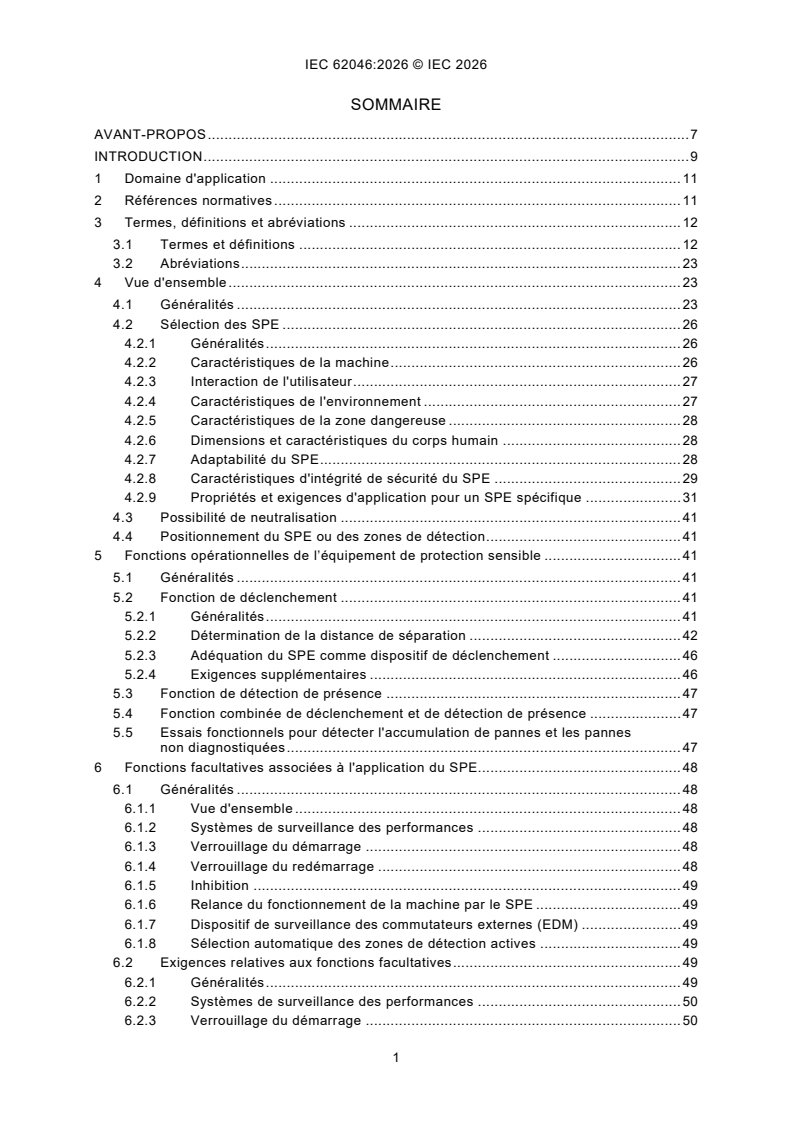
SOMMAIRE
AVANT-PROPOS . 7
INTRODUCTION . 9
1 Domaine d'application . 11
2 Références normatives . 11
3 Termes, définitions et abréviations . 12
3.1 Termes et définitions . 12
3.2 Abréviations . 23
4 Vue d'ensemble . 23
4.1 Généralités . 23
4.2 Sélection des SPE . 26
4.2.1 Généralités . 26
4.2.2 Caractéristiques de la machine . 26
4.2.3 Interaction de l'utilisateur . 27
4.2.4 Caractéristiques de l'environnement . 27
4.2.5 Caractéristiques de la zone dangereuse . 28
4.2.6 Dimensions et caractéristiques du corps humain . 28
4.2.7 Adaptabilité du SPE . 28
4.2.8 Caractéristiques d'intégrité de sécurité du SPE . 29
4.2.9 Propriétés et exigences d'application pour un SPE spécifique . 31
4.3 Possibilité de neutralisation . 41
4.4 Positionnement du SPE ou des zones de détection . 41
5 Fonctions opérationnelles de l’équipement de protection sensible . 41
5.1 Généralités . 41
5.2 Fonction de déclenchement . 41
5.2.1 Généralités . 41
5.2.2 Détermination de la distance de séparation . 42
5.2.3 Adéquation du SPE comme dispositif de déclenchement . 46
5.2.4 Exigences supplémentaires . 46
5.3 Fonction de détection de présence . 47
5.4 Fonction combinée de déclenchement et de détection de présence . 47
5.5 Essais fonctionnels pour détecter l'accumulation de pannes et les pannes
non diagnostiquées . 47
6 Fonctions facultatives associées à l'application du SPE. 48
6.1 Généralités . 48
6.1.1 Vue d'ensemble . 48
6.1.2 Systèmes de surveillance des performances . 48
6.1.3 Verrouillage du démarrage . 48
6.1.4 Verrouillage du redémarrage . 48
6.1.5 Inhibition . 49
6.1.6 Relance du fonctionnement de la machine par le SPE . 49
6.1.7 Dispositif de surveillance des commutateurs externes (EDM) . 49
6.1.8 Sélection automatique des zones de détection actives . 49
6.2 Exigences relatives aux fonctions facultatives . 49
6.2.1 Généralités . 49
6.2.2 Systèmes de surveillance des performances . 50
6.2.3 Verrouillage du démarrage . 50
6.2.4 Verrouillage du redémarrage . 50
6.2.5 Inhibition . 51
6.2.6 Relance du fonctionnement de la machine par l'AOPD. 55
6.2.7 Sélection automatique des zones de détection actives . 57
7 Intégration au système de commande relatif à la sécurité . 58
8 Examen et essai . 58
8.1 Généralités . 58
8.2 Vérifications fonctionnelles . 58
8.3 Inspection périodique . 59
8.4 Examen et essai initiaux . 60
8.5 Essais spécifiques à l'application . 61
9 Informations pour l'utilisation . 62
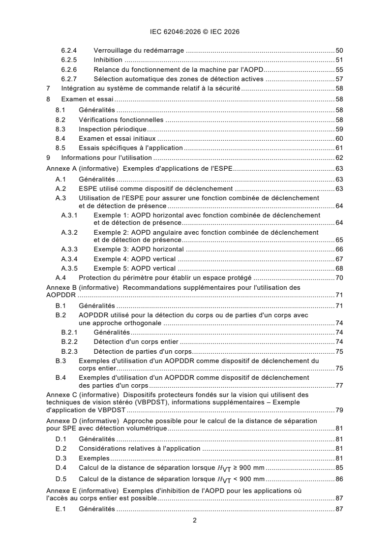
Annexe A (informative) Exemples d'applications de l'ESPE . 63
A.1 Généralités . 63
A.2 ESPE utilisé comme dispositif de déclenchement . 63
A.3 Utilisation de l'ESPE pour assurer une fonction combinée de déclenchement
et de détection de présence . 64
A.3.1 Exemple 1: AOPD horizontal avec fonction combinée de déclenchement
et de détection de présence . 64
A.3.2 Exemple 2: AOPD angulaire avec fonction combinée de déclenchement
et de détection de présence . 65
A.3.3 Exemple 3: AOPD horizontal . 66
A.3.4 Exemple 4: AOPD vertical . 67
A.3.5 Exemple 5: AOPD vertical . 68
A.4 Protection du périmètre pour établir un espace protégé . 70
Annexe B (informative) Recommandations supplémentaires pour l'utilisation des
AOPDDR . 71
B.1 Généralités . 71
B.2 AOPDDR utilisé pour la détection du corps ou de parties d'un corps avec
une approche orthogonale . 74
B.2.1 Généralités . 74
B.2.2 Détection d'un corps entier . 74
B.2.3 Détection de parties d'un corps. 75
B.3 Exemples d'utilisation d'un AOPDDR comme dispositif de déclenchement du
corps entier . 75
B.4 Exemples d'utilisation d'un AOPDDR comme dispositif de déclenchement
des parties d'un corps . 77
Annexe C (informative) Dispositifs protecteurs fondés sur la vision qui utilisent des
techniques de vision stéréo (VBPDST), informations supplémentaires – Exemple
d'application de VBPDST . 79
Annexe D (informative) Approche possible pour le calcul de la distance de séparation
pour SPE avec détection volumétrique . 81
D.1 Généralités . 81
D.2 Considérations relatives à l'application . 81
D.3 Exemples . 81
D.4 Calcul de la distance de séparation lorsque H ≥ 900 mm . 85
VT
D.5 Calcul de la distance de séparation lorsque H < 900 mm . 86
VT
Annexe E (informative) Exemples d'inhibition de l'AOPD pour les applications où
l'accès au corps entier est possible . 87
E.1 Généralités . 87
E.2 Quatre capteurs d'inhibition . 90
E.2.1 Quatre capteurs d'inhibition à faisceaux parallèles – Positionnement . 90
E.2.2 Quatre capteurs d'inhibition à faisceaux parallèles – Commande
séquentielle . 94
E.2.3 Quatre capteurs d'inhibition à faisceaux parallèles – Commande
temporelle . 95
E.2.4 Quatre capteurs d'inhibition à faisceaux parallèles – Connexion à une
commande d'inhibition à deux entrées . 96
E.3 Deux capteurs d'inhibition . 97
E.3.1 Deux capteurs d'inhibition à faisceaux croisés – Positionnement . 97
E.3.2 Deux capteurs d'inhibition à faisceaux croisés – Commande temporelle . 100
E.3.3 Deux capteurs d'inhibition à faisceaux croisés – Hauteur du point
d'intersection . 101
E.3.4 Deux capteurs d'inhibition à faisceaux parallèles – Sortie seulement . 102
E.4 Mesures de commande facultatives des systèmes de commande d'inhibition . 105
E.4.1 Généralités . 105
E.4.2 Commande de temporisation de l'inhibition . 105
E.4.3 Validation de l'inhibition . 107
E.4.4 Combinaison de la validation de l'inhibition et de la commande de
temporisation de l'inhibition . 109
E.4.5 Protection des écartements latéraux . 110
E.5 Exemple de protection d'un système de convoyeur . 114
Annexe F (informative) Commutation automatique des zones de détection actives . 117
F.1 Exemple de sélection automatique des zones de détection actives . 117
F.2 Exemples de sélection automatique des zones de détection actives pour
permettre le passage de matériaux à l'intérieur ou à l'extérieur d'une zone
dangereuse . 118
Annexe G (informative) Caractéristiques des SPE . 120
G.1 Équipement de protection électrosensible (ESPE) . 120
G.1.1 Types d'ESPE . 120
G.1.2 Dispositifs protecteurs optoélectroniques actifs (AOPD) . 120
G.1.3 Dispositifs protecteurs optoélectroniques actifs sensibles aux réflexions
diffuses (AOPDDR) . 121
G.1.4 Dispositifs protecteurs fondés sur la vision (VBPD) . 122
G.1.5 Dispositifs protecteurs fondés sur un radar (RPD) . 123
G.2 Planchers et tapis sensibles à la pression . 124
Annexe H (informative) Estimation du SIL ou PL pour les systèmes d'inhibition dans
les applications ESPE . 125
H.1 Généralités . 125
H.2 Conditions préalables et hypothèses pour le MS-SB . 126
H.3 Diagnostics . 126
H.4 Structure de sécurité . 127
H.4.1 MS-SB à 2 capteurs . 127
H.4.2 MS-SB à 4 capteurs . 127
H.5 Exemples de calculs . 128
H.5.1 Exemple conforme à l'ISO 13849-1 . 128
H.5.2 Exemple conforme à l'IEC 62061 . 129
H.6 Défaillances de cause commune . 132
Bibliographie . 133
Figure 1 – Relations du présent document avec d'autres normes . 10
Figure 2 – Processus de réduction du risque . 25
Figure 3 – Exemple de l'effet des surfaces réfléchissantes . 31
Figure 4 – Capacité de détection d'un dispositif à faisceau lumineux unique . 33
Figure 5 – Capacité de détection d'un dispositif à faisceaux lumineux multiples . 33
Figure 6 – Exemple d'utilisation du blanking . 36
Figure 7 – Exemple de résolution réduite . 37
Figure 8 – Personne qui franchit une zone de détection à deux dimensions . 45
Figure 9 – Personne qui franchit une zone de détection horizontale ou à trois
dimensions . 45
Figure A.1 – ESPE utilisé comme dispositif de déclenchement . 63
Figure A.2 – AOPD utilisé pour assurer une fonction combinée de déclenchement et de
détection de présence – Exemple 1 . 64
Figure A.3 – AOPD utilisé pour assurer une fonction combinée de déclenchement et de
détection de présence – Exemple 2 . 65
Figure A.4 – AOPD horizontal – Exemple 3 . 66
Figure A.5 – AOPD vertical – Exemple 4 . 67
Figure A.6 – Distance de séparation augmentée – Exemple 5 . 68
Figure A.7 – Protecteurs supplémentaires. 69
Figure A.8 – Utilisation d'un dispositif de déclenchement . 70
Figure B.1 – Zone de détection d'un AOPDDR à deux dimensions . 72
Figure B.2 – Zone de détection d'un AOPDDR à trois dimensions . 73
Figure B.3 – Utilisation d'un AOPDDR comme dispositif de déclenchement du corps
entier – Exemple 1 . 75
Figure B.4 – Utilisation d'un AOPDDR comme dispositif de déclenchement du corps
entier – Exemple 2 . 76
Figure B.5 – Utilisation d'un AOPDDR comme dispositif de déclenchement des parties
d'un corps – Exemple 3 . 77
Figure B.6 – Utilisation d'un AOPDDR comme dispositif de déclenchement des parties
d'un corps – Exemple 4 . 77
Figure C.1 – Exemple d'application d'un VBPDST . 80
Figure D.1 – Approche lorsque H ≥ 900 mm (orthogonale) . 82
VT
Figure D.2 – Approche lorsque H < 900 mm (parallèle) . 83
VT
Figure D.3 – Approche lorsque H ≥ 900 mm (orthogonale) . 84
VT
Figure D.4 – Approche lorsque H < 900 mm (parallèle) . 85
VT
Figure E.1 – Configuration T avec quatre capteurs d'inhibition à faisceaux parallèles,
commande temporelle ou séquentielle . 88
Figure E.2 – Configuration X avec deux capteurs d'inhibition à faisceaux croisés et
commande temporelle . 88
Figure E.3 – Configuration L avec deux capteurs d'inhibition à faisceaux parallèles,
commande temporelle ou séquentielle . 89
Figure E.4 – Taille de l'écartement à côté du matériau transporté, par exemple une
palette . 90
Figure E.5 – Quatre capteurs d'inhibition à faisceaux parallèles . 91
Figure E.6 – Distances minimales entre les faisceaux des capteurs
d'inhibition MS1 et MS2 . 92
Figure E.7 – Positionnement de la hauteur de montage des capteurs d'inhibition . 92
Figure E.8 – Éviter la manipulation de l'inhibition par des capteurs de proximité . 93
Figure E.9 – Les capteurs d'inhibition à faisceaux croisés qui ne traversent pas
l'AOPD ne sont pas appropriés . 94
Figure E.10 – Séquence de signaux: quatre faisceaux parallèles de capteurs
d'inhibition avec commande séquentielle . 95
Figure E.11 – Séquence de signaux: quatre faisceaux parallèles de capteurs
d'inhibition avec commande temporelle . 96
Figure E.12 – Connexion de quatre capteurs d'inhibition à une commande à deux
entrées . 97
Figure E.13 – Positionnement de deux capteurs d'inhibition à faisceaux croisés . 98
Figure E.14 – Deux capteurs d'inhibition à faisceaux croisés avec risque d'entrer dans
la zone dangereuse . 100
Figure E.15 – Séquence de signaux et séquence temporelle de deux capteurs
d'inhibition à faisceaux croisés . 101
Figure E.16 – Hauteur du point d'intersection. 102
Figure E.17 – Deux capteurs d'inhibition à faisceaux parallèles – Sortie seulement . 103
Figure E.18 – Diagramme de signaux; deux capteurs d'inhibition à faisceaux
parallèles – Sortie seulement, commande temporelle et inhibition interrompue par
l'AOPD . 104
Figure E.19 – Diagramme de signaux; deux capteurs d'inhibition à faisceaux
parallèles – Sortie seulement, commande séquentielle et inhibition interrompue par le
minuteur . 104
Figure E.20 – Diagramme de signaux; temporisation d'inhibition non commandée avec
inhibition à deux faisceaux . 106
Figure E.21 – Diagramme de signaux; temporisation d'inhibition commandée par le
signal du convoyeur . 107
Figure E.22 – Exemple de séquence de signaux avec un signal de validation de
l'inhibition statique . 108
Figure E.23 – Séquence de signaux d'un signal de validation de l'inhibition dynamique . 109
Figure E.24 – Séquence de signaux d'un signal combiné de validation de l'inhibition et
de commande de temporisation . 110
Figure E.25 – Protection des écartements latéraux par des portes battantes
supplémentaires – Vue du dessus. 111
Figure E.26 – Protection des écartements latéraux par des portes battantes
supplémentaires – Vue de face . 112
Figure E.27 – Utilisation de portes battantes avec l'inhibition . 113
Figure E.28 – Protection des écartements latéraux dans un système d'inhibition par un
AOPD vertical supplémentaire . 114
Figure E.29 – Chaîne de production incorporant deux convoyeurs (deux zones
dangereuses) (application incorrecte) . 115
Figure E.30 – Chaîne de production incorporant deux convoyeurs (deux zones
dangereuses) . 116
Figure F.1 – Exemple de sélection automatique des zones de détection actives . 118
Figure F.2 – Exemple de sélection automatique de la zone de détection avec un AOPD
(barrière immatérielle) . 119
Figure F.3 – Exemple de sélection automatique de la zone de détection avec un
AOPDDR monté verticalement . 119
Figure G.1 – Principe de détection de l'AOPD à faisceaux . 120
Figure G.2 – AOPD à faisceaux utilisant des miroirs . 121
Figure G.3 – AOPD de rétroréflexion . 121
Figure G.4 – Principe de détection de l'AOPDDR . 122
Figure G.5 – Principe de détection du VBPDST . 123
Figure G.6 – Principe de détection du RPD . 124
Figure H.1 – Schéma fonctionnel de sécurité général d'un système d'inhibition . 125
Figure H.2 – Schéma fonctionnel de sécurité d'un MS-SB à 2 capteurs. 127
Figure H.3 – Schéma fonctionnel de sécurité d'un MS-SB à 4 capteurs et de sa
prétransformation . 128
Tableau 1 – Types d'ESPE et de PL ou SIL réalisables . 30
Tableau D.1 – Vue d'ensemble de l'approche orthogonale par rapport à l'approche
parallèle. 82
Tableau E.1 – Table de vérité, quatre capteurs d'inhibition à faisceaux parallèles avec
commande séquentielle . 94
Tableau H.1 Performances en matière de sécurité des sous-systèmes de capteurs
d'inhibition selon l'ISO 13849-1 . 129
Tableau H.2 – Performances en matière de sécurité des sous-systèmes de capteurs
d'inhibition selon l'IEC 62061 . 131
COMMISSION ÉLECTROTECHNIQUE INTERNATIONALE
____________
Sécurité des machines -
Application des équipements de protection
à la détection de la présence de personnes
AVANT-PROPOS
1) La Commission Électrotechnique Internationale (IEC) est une organisation mondiale de normalisation composée
de l'ensemble des comités électrotechniques nationaux (Comités nationaux de l'IEC). L'IEC a pour objet de
favoriser la coopération internationale pour toutes les questions de normalisation dans les domaines de
l'électricité et de l'électronique. À cet effet, l'IEC – entre autres activités – publie des Normes internationales,
des Spécifications techniques, des Rapports techniques, des Spécifications accessibles au public (PAS) et des
Guides (ci-après dénommés "Publication(s) de l'IEC"). Leur élaboration est confiée à des comités d'études, aux
travaux desquels tout Comité national intéressé par le sujet traité peut participer. Les organisations
internationales, gouvernementales et non gouvernementales, en liaison avec l'IEC, participent également aux
travaux. L'IEC collabore étroitement avec l'Organisation Internationale de Normalisation (ISO), selon des
conditions fixées par accord entre les deux organisations.
2) Les décisions ou accords officiels de l'IEC concernant les questions techniques représentent, dans la mesure du
possible, un accord international sur les sujets étudiés, étant donné que les Comités nationaux de l'IEC intéressés
sont représentés dans chaque comité d'études.
3) Les Publications de l'IEC se présentent sous la forme de recommandations internationales et sont agréées
comme telles par les Comités nationaux de l'IEC. Tous les efforts raisonnables sont entrepris afin que l'IEC
s'assure de l'exactitude du contenu technique de ses publications; l'IEC ne peut pas être tenue responsable de
l'éventuelle mauvaise utilisation ou interprétation qui en est faite par un quelconque utilisateur final.
4) Dans le but d'encourager l'uniformité internationale, les Comités nationaux de l'IEC s'engagent, dans toute la
mesure possible, à appliquer de façon transparente les Publications de l'IEC dans leurs publications nationales
et régionales. Toutes divergences entre toutes Publications de l'IEC et toutes publications nationales ou
régionales correspondantes doivent être indiquées en termes clairs dans ces dernières.
5) L'IEC elle-même ne fournit aucune attestation de conformité. Des organismes de certification indépendants
fournissent des services d'évaluation de conformité et, dans certains secteurs, accèdent aux marques de
conformité de l'IEC. L'IEC n'est responsable d'aucun des services effectués par les organismes de certification
indépendants.
6) Tous les utilisateurs doivent s'assurer qu'ils sont en possession de la dernière édition de cette publication.
7) Aucune responsabilité ne doit être imputée à l'IEC, à ses administrateurs, employés, auxiliaires ou mandataires,
y compris ses experts particuliers et les membres de ses comités d'études et des Comités nationaux de l'IEC,
pour tout préjudice causé en cas de dommages corporels et matériels, ou de tout autre dommage de quelque
nature que ce soit, directe ou indirecte, ou pour supporter les coûts (y compris les frais de justice) et les dépenses
découlant de la publication ou de l'utilisation de cette Publication de l'IEC ou de toute autre Publication de l'IEC,
ou au crédit qui lui est accordé.
8) L'attention est attirée sur les références normatives citées dans cette publication. L'utilisation de publications
référencées est obligatoire pour une application correcte de la présente publication.
9) L'IEC attire l'attention sur le fait que la mise en application du présent document peut entraîner l'utilisation d'un
ou de plusieurs brevets. L'IEC ne prend pas position quant à la preuve, à la validité et à l'applicabilité de tout
droit de brevet revendiqué à cet égard. À la date de publication du présent document, l'IEC n'avait pas reçu
notification qu'un ou plusieurs brevets pouvaient être nécessaires à sa mise en application. Toutefois, il y a lieu
d'avertir les responsables de la mise en application du présent document que des informations plus récentes
sont susceptibles de figurer dans la base de données de brevets, disponible à l'adresse https://patents.iec.ch.
L'IEC ne saurait être tenue pour responsable de ne pas avoir identifié de tels droits de brevets.
L'IEC 62046 a été établie par le comité d'études 44 de l'IEC: Sécurité des machines – Aspects
électrotechniques. Il s'agit d'une Norme internationale.
Cette deuxième édition annule et remplace la première édition parue en 2018. Cette édition
constitue une révision technique.
Cette édition inclut les modifications techniques majeures suivantes par rapport à la première
édition:
a) le document a été restructuré pour guider l'utilisateur;
b) des informations supplémentaires ont été ajoutées pour les systèmes de vision et les
systèmes radars;
c) les exigences d'inhibition ont été mises à jour;
d) des informations sur l'accès au corps entier ont été ajoutées;
e) l'accès au corps entier est également traité de manière plus détaillée;
f) le document a été aligné sur les modifications apportées à l'ISO 13855.
Le texte de cette Norme internationale est issu des documents suivants:
Projet Rapport de vote
44/1080/FDIS 44/1088/RVD
Le rapport de vote indiqué dans le tableau ci-dessus donne toute information sur le vote ayant
abouti à son approbation.
La langue employée pour l'élaboration de cette Norme internationale est l'anglais.
Ce document a été rédigé selon les Directives ISO/IEC, Partie 2, il a été développé selon les
Directives ISO/IEC, Partie 1 et les Directives ISO/IEC, Supplément IEC, disponibles sous
www.iec.ch/members_experts/refdocs. Les principaux types de documents développés par
l'IEC sont décrits plus en détail sous www.iec.ch/publications.
Le comité a décidé que le contenu de ce document ne sera pas modifié avant la date de stabilité
indiquée sur le site web de l'IEC sous webstore.iec.ch dans les données relatives au document
recherché. À cette date, le document sera
– reconduit,
– supprimé, ou
– révisé.
INTRODUCTION
Le présent document fournit des exigences et des informations sur l'application des
équipements de protection sensibles (SPE) qui emploient des dispositifs de détection des
personnes, dans le but de réduire le plus possible un risque causé par des parties dangereuses
de machines, sans fournir de barrière matérielle.
L'objet du présent document est d'aider les comités de rédaction des normes en charge de
l'élaboration des normes machines (normes de Type C), les concepteurs, fabricants et sociétés
de remise en état des machines, les organismes de certification pour la sécurité des machines,
les administrations compétentes pour le lieu de travail et autres, sur l'application appropriée
des équipements de protection sensibles des machines.
La Figure 1 donne le contexte général et l'utilisation prévue du présent document.
Les Articles 1 à 5 et les Articles 7 et 8 du présent document s'appliquent à tous les équipements
de protection sensibles compris dans le domaine d'application. L'Article 6 contient les
recommandations pour l'application de types spécifiques d'équipements de protection
sensibles.
Les principes du présent document peuvent être utiles pour l'application de dispositifs qui
utilisent d'autres technologies de détection, même si le présent document ne définit aucune
exigence spécifique pour ces dispositifs.
Le présent document couvre les dispositifs normalisés dans les séries IEC 61496 et ISO 13856.
À moins qu'une norme relative à la sécurité spécifique au produit pour les dispositifs qui utilisent
d'autres technologies de détection n'ait été publiée, leur adaptabilité comme seuls moyens de
protection contre les phénomènes dangereux associés aux machines n'est pas connue. Il
convient de faire des recherches adéquates avant la sélection et l'utilisation de dispositifs pour
lesquels il n'existe aucune norme relative à la sécurité spécifique au produit. En effet, leur
comportement, en particulier dans des conditions de panne, n'est pas considéré comme
suffisamment prévisible.
Un niveau d'intégrité de sécurité (SIL, Safety Integrity Level, comme cela est décrit dans
l'IEC 62061 ou l'IEC 61508) ou un niveau de performance (PL, Performance Level, comme cela
est décrit dans l'ISO 13849-1) n'est pas une indication suffisante pour démontrer l'adaptabilité
d'un dispositif comme moyen de protection. L'adaptabilité dépend de l'existence de moyens de
détection adaptés, des conditions d'environnement, en particulier si elles peuvent altérer la
capacité de détection, du comportement en cas de panne, etc.
Figure 1 – Relations du présent document avec d'autres normes
1 Domaine d'application
Le présent document spécifie les exigences pour le choix, le positionnement, la configuration
et la mise en service des équipements de protection sensibles (SPE) prévus pour détecter la
présence momentanée ou permanente de personnes afin de protéger celles-ci contre les
parties dangereuses des machines dans des applications industrielles. Le présent document
couvre l'application des équipements de protection électrosensibles (ESPE) spécifiés dans la
série IEC 61496 ainsi que des tapis et planchers sensibles à la pression spécifiés dans
l'ISO 13856-1.
Il tient compte des caractéristiques des machines, des équipements de protection sensibles,
de l'environnement et de l'interaction humaine par des personnes de 14 ans et plus.
Le présent document inclut des annexes informatives qui fournissent des recommandations sur
l'application des équipements de protection sensibles pour détecter la présence de personnes.
Ces annexes contiennent des exemples pour expliquer les principes définis dans le présent
document. Ces exemples ne sont pas réputés représenter des solutions uniques à une
application donnée ni constituer une limitation à l'innovation ou aux avancées technologiques.
Ces exemples sont fournis uniquement comme des solutions représentatives destinées à
expliquer certaines des notions d'intégration d'équipements de protection sensibles et ont été
simplifiés par souci de clarté. De ce fait, ils peuvent être incomplets.
Le présent document est destiné à être utilisé conjointement avec l'ISO 13855.
2 Références normatives
Les documents suivants sont cités dans le texte de sorte qu'ils constituent, pour tout ou partie
de leur contenu, des exigences du présent document. Pour les références datées, seule
l'édition citée s'applique. Pour les références non datées, la dernière édition du document de
référence s'applique (y compris les éventuels amendements).
IEC 62061:2021, Sécurité des machines - Sécurité fonctionnelle des systèmes de commande
relatifs à la sécurité
IEC 62061:2021/AMD1:2024
IEC TS 61496-4-2:2022, Safety of machinery - Electro-sensitive protective equipment -
Part 4-2: Particular requirements for equipment using vision based protective devices (VBPD) -
Additional requirements when using reference pattern techniques (VBPDPP) (disponible en
anglais seulement)
IEC TS 61496-4-3:2022, Safety of machinery - Electro-sensitive protective equipment -
Part 4-3: Particular requirements for equipment using vision based protective devices (VBPD) -
Additional requirements when using stereo vision techniques (VBPDST) (disponible en anglais
seulement)
ISO 13849-1:2023, Sécurité des machines - Parties des systèmes de commande relatives à la
sécurité - Partie 1: Principes généraux de conception
ISO 13855:2024, Sécurité des machines - Positionnement des moyens de protection par
rapport à l'approche du corps humain
3 Termes, définitions et abréviations
3.1 Termes et définitions
Pour les besoins du présent document, les termes et définitions suivants s'appliquent.
L'ISO et l'IEC tiennent à jour des bases de données terminologiques destinées à être utilisées
en normalisation, consultables aux adresses suivantes:
– IEC Electropedia: disponible à l'adresse https://www.electropedia.org/
– ISO Online browsing platform: disponible à l'adresse https://www.iso.org/obp
3.1.1
dispositif protecteur optoélectronique actif
AOPD
dispositif dont la fonction de détection est accomplie par des émetteurs et récepteurs
optoélectroniques qui détectent l'interruption de tout rayonnement optique généré, à l'intérieur
du dispositif, par un objet opaque présent dans la zone spécifique de détection (ou, pour un
dispositif à faisceaux lumineux, sur l'axe du faisceau lumineux)
Note 1 à l'article: L'abréviation "AOPD" est dérivée du terme anglais développé correspondant "active
optoelectronic protective device".
[SOURCE: IEC 61496-2:2020, 3.201, modifié – La note à l'article a été supprimée.]
3.1.2
dispositif protecteur optoélectronique actif sensible aux réflexions diffuses
AOPDDR
assemblage qui utilise un rayon
...