


IEC 62228-7:2026
(Main)Integrated circuits - EMC evaluation of transceivers - Part 7: CXPI transceivers
General Information
- Abstract
IEC 62228-7:2026 specifies test and measurement methods for the EMC evaluation of CXPI transceiver ICs under network condition. It defines test configurations, test conditions, test signals, failure criteria, test procedures, test setups and test boards. This specification is applicable for standard CXPI transceiver ICs and ICs with embedded CXPI transceiver and covers:
- the emission of RF disturbances;
- the immunity against RF disturbances;
- the immunity against impulses;
- the immunity against electrostatic discharges (ESD).
This edition includes the following significant technical changes with respect to the previous edition:
a) change transceiver terms and definitions from master to commander and slave to responder in 3.1.5 and 3.1.6.
b) change test configuration for embedded transceiver in 5.3.1 and add on Figure A.4 accordingly.
c) change the definition of TX2 test signal for Type-B transceiver in 5.4.2.
d) add examples for test limits in Annex C.
- Status
- Published
- Publication Date
- 12-Jul-2026
- Technical Committee
- SC 47A - Integrated circuits
- Drafting Committee
- WG 9 - TC 47/SC 47A/WG 9
- Current Stage
- PPUB - Publication issued
- Start Date
- 13-Jul-2026
- Completion Date
- 07-Jul-2026
Buy Documents
REDLINE IEC 62228-7:2026 RLV - Integrated circuits - EMC evaluation of transceivers - Part 7: CXPI transceivers
iec62228-7{ed2.0}en - Integrated circuits - EMC evaluation of transceivers - Part 7: CXPI transceivers
iec62228-7{ed2.0}fr - Circuits intégrés - Évaluation de la CEM des émetteurs-récepteurs - Partie 7: Émetteurs-récepteurs CXPI
Overview
IEC 62228-7:2026 is an international standard developed by the International Electrotechnical Commission (IEC) for the electromagnetic compatibility (EMC) evaluation of CXPI transceiver integrated circuits (ICs). Targeting both standalone CXPI transceivers and ICs with embedded CXPI transceivers, this standard specifies test and measurement methods under network application conditions. It defines the following aspects to ensure comprehensive EMC validation:
- Test configurations and setups
- Test conditions and signals
- Failure criteria and evaluation procedures
- Test boards for CXPI transceivers
This document is highly relevant for engineers, design and quality assurance professionals, and manufacturers engaged in developing or certifying automotive electronics, particularly those using CXPI (Clock Extension Peripheral Interface) communications.
Key Topics
EMC Evaluation Scope
IEC 62228-7:2026 covers EMC performance for CXPI transceivers in several critical areas:
- Emission of RF Disturbances: How much undesirable radio frequency energy is emitted by the IC, potentially impacting nearby circuits.
- Immunity to RF Disturbances: The ability of the IC to operate correctly in the presence of external RF noise.
- Immunity to Impulses: Resistance to transient electrical disturbances.
- Immunity to Electrostatic Discharge (ESD): The ability to withstand and operate reliably after exposure to ESD events.
Test Methods and Conditions
- Modes of Operation: Tests are conducted in various power and network conditions relevant to automotive CXPI applications.
- Test Configurations: Includes both powered (functional) and unpowered (passive, for ESD) test modes, using representative evaluation test boards.
- Test Signals: Defined signals and scenarios to ensure repeatable and comprehensive assessment.
- Failure Criteria: Clear, standardized outcomes for pass/fail determinations enhance reliability and comparability.
Technical Updates in 2026 Edition
- Updated terminology: "Commander" replaces "Master"; "Responder" replaces "Slave."
- Improved test configuration for embedded transceivers and clarified associated diagrams.
- Revised test signal definitions for specific transceiver types.
- New example test limits for real-world automotive scenarios.
Applications
IEC 62228-7:2026 is especially practical for:
- Automotive Electronics: Ensuring EMC robustness in vehicles using CXPI networks for body electronics, control units, and sensor communications.
- IC Design and Manufacturing: Providing guidelines to test, evaluate, and certify CXPI ICs during development and production.
- Compliance and Certification: Supporting regulatory approval processes for automotive electronics by providing standardized EMC testing procedures.
- System Integration: Assisting OEMs and system integrators in verifying the EMC performance of complete vehicle networks.
Following IEC 62228-7:2026 ensures automotive systems are less susceptible to electromagnetic interference, reducing the risk of unexpected malfunctions and supporting reliability in safety-critical applications.
Related Standards
IEC 62228-7:2026 references and aligns with a suite of international standards that detail EMC testing methods, CXPI protocol specifications, and component requirements for automotive applications. Key related standards include:
- IEC 61967 series: Methods for measuring electromagnetic emissions from integrated circuits.
- IEC 62132 series: Methods for measuring electromagnetic immunity of integrated circuits.
- IEC 62215 series: Methods for testing immunity to electrical impulses.
- IEC 62228-1: General conditions and definitions for EMC evaluation of transceivers.
- ISO 7637-2: Road vehicle conducted electrical transient emissions.
- ISO 10605: Methods for assessing electrostatic discharge (ESD) effects in road vehicles.
- ISO 20794-4 and ISO 20794-7: Specifications and testing for the CXPI protocol’s physical and data link layers.
By following IEC 62228-7:2026 alongside these related standards, stakeholders ensure a robust, harmonized approach to EMC compliance for CXPI-based automotive systems.
Relations
- Revises
IEC 62228-7:2022 - Integrated circuits - EMC evaluation of transceivers - Part 7: CXPI transceivers - Effective Date
- 06-Sep-2024
Buy Documents
REDLINE IEC 62228-7:2026 RLV - Integrated circuits - EMC evaluation of transceivers - Part 7: CXPI transceivers
iec62228-7{ed2.0}en - Integrated circuits - EMC evaluation of transceivers - Part 7: CXPI transceivers
iec62228-7{ed2.0}fr - Circuits intégrés - Évaluation de la CEM des émetteurs-récepteurs - Partie 7: Émetteurs-récepteurs CXPI
Frequently Asked Questions
IEC 62228-7:2026 is a standard published by the International Electrotechnical Commission (IEC). Its full title is "Integrated circuits - EMC evaluation of transceivers - Part 7: CXPI transceivers". This standard covers: IEC 62228-7:2026 specifies test and measurement methods for the EMC evaluation of CXPI transceiver ICs under network condition. It defines test configurations, test conditions, test signals, failure criteria, test procedures, test setups and test boards. This specification is applicable for standard CXPI transceiver ICs and ICs with embedded CXPI transceiver and covers: - the emission of RF disturbances; - the immunity against RF disturbances; - the immunity against impulses; - the immunity against electrostatic discharges (ESD). This edition includes the following significant technical changes with respect to the previous edition: a) change transceiver terms and definitions from master to commander and slave to responder in 3.1.5 and 3.1.6. b) change test configuration for embedded transceiver in 5.3.1 and add on Figure A.4 accordingly. c) change the definition of TX2 test signal for Type-B transceiver in 5.4.2. d) add examples for test limits in Annex C.
IEC 62228-7:2026 specifies test and measurement methods for the EMC evaluation of CXPI transceiver ICs under network condition. It defines test configurations, test conditions, test signals, failure criteria, test procedures, test setups and test boards. This specification is applicable for standard CXPI transceiver ICs and ICs with embedded CXPI transceiver and covers: - the emission of RF disturbances; - the immunity against RF disturbances; - the immunity against impulses; - the immunity against electrostatic discharges (ESD). This edition includes the following significant technical changes with respect to the previous edition: a) change transceiver terms and definitions from master to commander and slave to responder in 3.1.5 and 3.1.6. b) change test configuration for embedded transceiver in 5.3.1 and add on Figure A.4 accordingly. c) change the definition of TX2 test signal for Type-B transceiver in 5.4.2. d) add examples for test limits in Annex C.
IEC 62228-7:2026 is classified under the following ICS (International Classification for Standards) categories: 31.200 - Integrated circuits. Microelectronics. The ICS classification helps identify the subject area and facilitates finding related standards.
IEC 62228-7:2026 has the following relationships with other standards: It is inter standard links to IEC 62228-7:2022. Understanding these relationships helps ensure you are using the most current and applicable version of the standard.
IEC 62228-7:2026 is available in PDF format for immediate download after purchase. The document can be added to your cart and obtained through the secure checkout process. Digital delivery ensures instant access to the complete standard document.
Standards Content (Sample)
IEC 62228-7 ®
Edition 2.0 2026-07
INTERNATIONAL
STANDARD
REDLINE VERSION
Integrated circuits - EMC evaluation of transceivers -
Part 7: CXPI transceivers
ICS 31.200 ISBN 978-2-8327-1388-4
All rights reserved. Unless otherwise specified, no part of this publication may be reproduced or utilized in any form or
by any means, electronic or mechanical, including photocopying and microfilm, without permission in writing from either
IEC or IEC's member National Committee in the country of the requester. If you have any questions about IEC copyright
or have an enquiry about obtaining additional rights to this publication, please contact the address below or your local
IEC member National Committee for further information.
IEC Secretariat Tel.: +41 22 919 02 11
3, rue de Varembé info@iec.ch
CH-1211 Geneva 20 www.iec.ch
Switzerland
About the IEC
The International Electrotechnical Commission (IEC) is the leading global organization that prepares and publishes
International Standards for all electrical, electronic and related technologies.
About IEC publications
The technical content of IEC publications is kept under constant review by the IEC. Please make sure that you have the
latest edition, a corrigendum or an amendment might have been published.
IEC publications search - IEC Products & Services Portal - products.iec.ch
webstore.iec.ch/advsearchform Discover our powerful search engine and read freely all the
The advanced search enables to find IEC publications by a publications previews, graphical symbols and the glossary.
variety of criteria (reference number, text, technical With a subscription you will always have access to up to date
committee, …). It also gives information on projects, content tailored to your needs.
replaced and withdrawn publications.
Electropedia - www.electropedia.org
The world's leading online dictionary on electrotechnology,
IEC Just Published - webstore.iec.ch/justpublished
Stay up to date on all new IEC publications. Just Published containing more than 22 500 terminological entries in English
details all new publications released. Available online and and French, with equivalent terms in 25 additional languages.
once a month by email. Also known as the International Electrotechnical Vocabulary
(IEV) online.
IEC Customer Service Centre - webstore.iec.ch/csc
If you wish to give us your feedback on this publication or
need further assistance, please contact the Customer
Service Centre: sales@iec.ch.
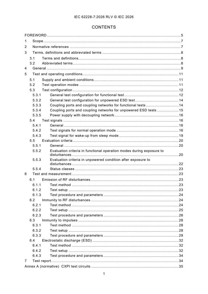
CONTENTS
FOREWORD . 5
1 Scope . 7
2 Normative references . 7
3 Terms, definitions and abbreviated terms . 8
3.1 Terms and definitions . 8
3.2 Abbreviated terms . 8
4 General . 9
5 Test and operating conditions . 11
5.1 Supply and ambient conditions. 11
5.2 Test operation modes . 11
5.3 Test configuration . 12
5.3.1 General test configuration for functional test . 12
5.3.2 General test configuration for unpowered ESD test . 14
5.3.3 Coupling ports and coupling networks for functional tests . 14
5.3.4 Coupling ports and coupling networks for unpowered ESD tests . 15
5.3.5 Power supply with decoupling network . 16
5.4 Test signals . 16
5.4.1 General . 16
5.4.2 Test signals for normal operation mode . 16
5.4.3 Test signal for wake-up from sleep mode . 19
5.5 Evaluation criteria . 20
5.5.1 General . 20
5.5.2 Evaluation criteria in functional operation modes during exposure to
disturbances . 20
5.5.3 Evaluation criteria in unpowered condition after exposure to
disturbances . 22
5.5.4 Status classes . 23
6 Test and measurement . 23
6.1 Emission of RF disturbances . 23
6.1.1 Test method . 23
6.1.2 Test setup . 23
6.1.3 Test procedure and parameters . 24
6.2 Immunity to RF disturbances . 24
6.2.1 Test method . 24
6.2.2 Test setup . 25
6.2.3 Test procedure and parameters . 26
6.3 Immunity to impulses . 28
6.3.1 Test method . 28
6.3.2 Test setup . 28
6.3.3 Test procedure and parameters . 29
6.4 Electrostatic discharge (ESD) . 32
6.4.1 Test method . 32
6.4.2 Test setup . 32
6.4.3 Test procedure and parameters . 34
7 Test report . 34
Annex A (normative) CXPI test circuits . 35
A.1 General . 35
A.2 CXPI test circuit for functional tests on standard type-A CXPI transceiver ICs . 35
A.3 CXPI test circuit for functional tests on standard type-B CXPI transceiver ICs . 38
A.4 CXPI test circuit for functional tests on ICs with embedded CXPI transceiver . 40
A.5 CXPI test circuit for unpowered ESD test on a standard type-A CXPI
transceiver IC . 43
A.6 CXPI test circuit for unpowered ESD test on a standard type-B CXPI
transceiver IC . 43
Annex B (normative) Test circuit boards. 45
B.1 Test circuit board for functional tests . 45
B.2 ESD test . 46
Annex C (informative) Examples for test limits for CXPI transceiver in automotive
application . 47
C.1 General . 47
C.2 Emission of RF disturbances . 47
C.3 Immunity to RF disturbances . 48
C.4 Immunity to impulse . 49
C.5 Electrostatic discharge (ESD) . 50
Annex D (informative) Example of setting for test signals . 51
Annex E (informative) Points to note for impulse immunity measurement for functional
status class A . 53
IC
E.1 General . 53
E.2 Points to note when testing pulse 1 . 53
Bibliography . 55
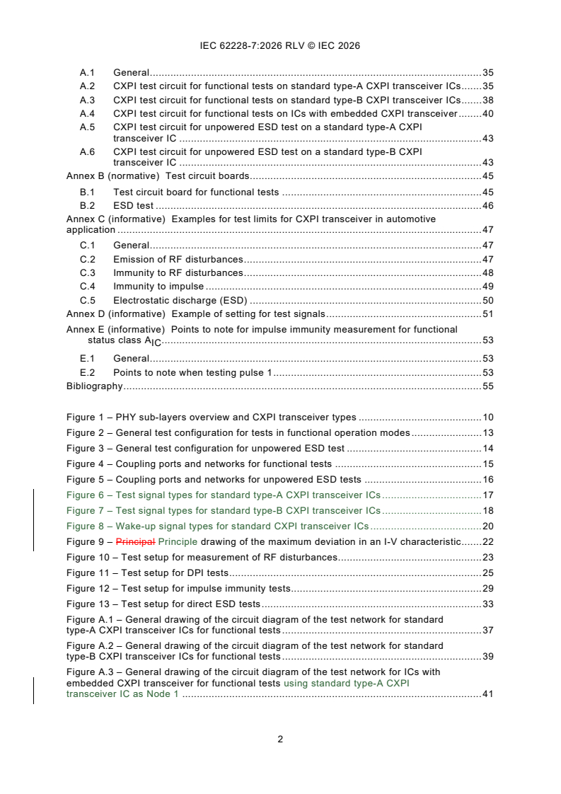
Figure 1 – PHY sub-layers overview and CXPI transceiver types . 10
Figure 2 – General test configuration for tests in functional operation modes . 13
Figure 3 – General test configuration for unpowered ESD test . 14
Figure 4 – Coupling ports and networks for functional tests . 15
Figure 5 – Coupling ports and networks for unpowered ESD tests . 16
Figure 6 – Test signal types for standard type-A CXPI transceiver ICs . 17
Figure 7 – Test signal types for standard type-B CXPI transceiver ICs . 18
Figure 8 – Wake-up signal types for standard CXPI transceiver ICs . 20
Figure 9 – Principal Principle drawing of the maximum deviation in an I-V characteristic . 22
Figure 10 – Test setup for measurement of RF disturbances. 23
Figure 11 – Test setup for DPI tests . 25
Figure 12 – Test setup for impulse immunity tests. 29
Figure 13 – Test setup for direct ESD tests . 33
Figure A.1 – General drawing of the circuit diagram of the test network for standard
type-A CXPI transceiver ICs for functional tests . 37
Figure A.2 – General drawing of the circuit diagram of the test network for standard
type-B CXPI transceiver ICs for functional tests . 39
Figure A.3 – General drawing of the circuit diagram of the test network for ICs with
embedded CXPI transceiver for functional tests using standard type-A CXPI
transceiver IC as Node 1 . 41
Figure A.4 – General drawing of the circuit diagram of the test network for ICs with
embedded CXPI transceiver for functional tests using IC with embedded CXPI
transceiver as Node 1 . 42
Figure A.5 – A general drawing of the test circuit diagram for testing direct ESD of
CXPI transceiver in unpowered mode . 43
Figure A.6 – A general drawing of the test circuit diagram for testing direct ESD of
CXPI standard Type-B transceiver in unpowered mode . 44
Figure B.1 – Example of IC interconnections of CXPI signal . 45
Figure B.2 – Example of ESD test board for CXPI transceiver ICs . 46
Figure C.1 – Example of limits for RF emission – CXPI . 47
Figure C.2 – Example of limits for RF emission – VBAT . 47
Figure C.3 – Example of limits for RF immunity for functional status class A – CXPI . 48
IC
Figure C.4 – Example of limits for RF immunity for functional status class A – VBAT . 48
IC
Figure C.5 – Example of limits for RF immunity for functional status class C or D –
IC IC
CXPI . 49
Figure C.6 – Example of limits for RF immunity for functional status class C or D –
IC IC
VBAT . 49
Figure D.1 – Example of signal setting for standard type-A in two transceiver
configuration . 51
Figure D.2 – Example of signal setting for standard type-B in two transceiver
configuration . 52
Figure E.1 – Relationship between ISO 7637-2 pulse 1 and transceiver VBAT supply . 53
Figure E.2 – Transceiver VBAT supply image when t time is shortened . 54
Table 1 – Types for CXPI transceiver . 9
Table 2 – Overview of required measurement and tests . 10
Table 3 – Supply and ambient conditions for functional operation . 11
Table 4 – Definition of coupling ports and coupling network components for functional
tests . 15
Table 5 – Definitions of coupling ports for unpowered ESD tests . 16
Table 6 – Communication test signal TX1 . 17
Table 7 – Communication test signal TX2 . 17
Table 8 – Communication test signal TX3 . 19
Table 9 – Wake-up test signal TX4 . 20
Table 10 – Evaluation criteria for standard type-A in functional operation modes . 21
Table 11 – Evaluation criteria for standard type-B in functional operation modes . 21
Table 12 – Evaluation criteria for ICs with embedded CXPI transceiver in functional
operation modes . 22
Table 13 – Parameters for emission measurements . 24
Table 14 – Settings for the RF measurement equipment . 24
Table 15 – Specifications for DPI tests . 26
Table 16 – Required DPI tests for functional status class A evaluation of standard
IC
type-A . 27
Table 17 – Required DPI tests for functional status class A evaluation of standard
IC
type-B . 27
Table 18 – Required DPI tests for functional status class A evaluation of ICs with
IC
embedded CXPI transceiver. 27
Table 19 – Required DPI tests for functional status class C , D1 or D2 evaluation
IC IC IC
of standard CXPI transceiver ICs and ICs with embedded CXPI transceiver . 28
Table 20 – Specifications for impulse immunity tests . 30
Table 21 – Parameters for impulse immunity tests . 30
Table 22 – Required impulse immunity tests for functional status class A evaluation
IC
of standard type-A . 31
Table 23 – Required impulse immunity tests for functional status class A evaluation
IC
of standard type-B . 31
Table 24 – Required impulse immunity tests for functional status class A evaluation
IC
of ICs with embedded CXPI transceiver . 31
Table 25 – Required impulse immunity tests for functional status class C , D1 or
IC IC
D2 evaluation of standard CXPI transceiver ICs and ICs with embedded CXPI
IC
transceiver . 32
Table 26 – Specifications for direct ESD tests . 34
Table B.1 – Parameter ESD test circuit board . 46
Table C.1 – Example of limits for impulse immunity for functional status
class C or D . 49
IC IC
INTERNATIONAL ELECTROTECHNICAL COMMISSION
____________
Integrated circuits - EMC evaluation of transceivers -
Part 7: CXPI transceivers
FOREWORD
1) The International Electrotechnical Commission (IEC) is a worldwide organization for standardization comprising
all national electrotechnical committees (IEC National Committees). The object of IEC is to promote international
co-operation on all questions concerning standardization in the electrical and electronic fields. To this end and
in addition to other activities, IEC publishes International Standards, Technical Specifications, Technical Reports,
Publicly Available Specifications (PAS) and Guides (hereafter referred to as "IEC Publication(s)"). Their
preparation is entrusted to technical committees; any IEC National Committee interested in the subject dealt with
may participate in this preparatory work. International, governmental and non-governmental organizations liaising
with the IEC also participate in this preparation. IEC collaborates closely with the International Organization for
Standardization (ISO) in accordance with conditions determined by agreement between the two organizations.
2) The formal decisions or agreements of IEC on technical matters express, as nearly as possible, an international
consensus of opinion on the relevant subjects since each technical committee has representation from all
interested IEC National Committees.
3) IEC Publications have the form of recommendations for international use and are accepted by IEC National
Committees in that sense. While all reasonable efforts are made to ensure that the technical content of IEC
Publications is accurate, IEC cannot be held responsible for the way in which they are used or for any
misinterpretation by any end user.
4) In order to promote international uniformity, IEC National Committees undertake to apply IEC Publications
transparently to the maximum extent possible in their national and regional publications. Any divergence between
any IEC Publication and the corresponding national or regional publication shall be clearly indicated in the latter.
5) IEC itself does not provide any attestation of conformity. Independent certification bodies provide conformity
assessment services and, in some areas, access to IEC marks of conformity. IEC is not responsible for any
services carried out by independent certification bodies.
6) All users should ensure that they have the latest edition of this publication.
7) No liability shall attach to IEC or its directors, employees, servants or agents including individual experts and
members of its technical committees and IEC National Committees for any personal injury, property damage or
other damage of any nature whatsoever, whether direct or indirect, or for costs (including legal fees) and
expenses arising out of the publication, use of, or reliance upon, this IEC Publication or any other IEC
Publications.
8) Attention is drawn to the Normative references cited in this publication. Use of the referenced publications is
indispensable for the correct application of this publication.
9) IEC draws attention to the possibility that the implementation of this document may involve the use of (a)
patent(s). IEC takes no position concerning the evidence, validity or applicability of any claimed patent rights in
respect thereof. As of the date of publication of this document, IEC had not received notice of (a) patent(s), which
may be required to implement this document. However, implementers are cautioned that this may not represent
the latest information, which may be obtained from the patent database available at https://patents.iec.ch. IEC
shall not be held responsible for identifying any or all such patent rights.
This redline version of the official IEC Standard allows the user to identify the changes made
to the previous edition IEC 62228-7:2022. A vertical bar appears in the margin wherever a
change has been made. Additions are in green text, deletions are in strikethrough red text.
IEC 62228-7 has been prepared by subcommittee 47A: Integrated circuits, of IEC technical
committee 47: Semiconductor devices. It is an International Standard.
This second edition cancels and replaces the first edition published in 2022. This edition
constitutes a technical revision.
This edition includes the following significant technical changes with respect to the previous
edition:
a) change transceiver terms and definitions from master to commander and slave to responder
in 3.1.5 and 3.1.6.
b) change test configuration for embedded transceiver in 5.3.1 and add on Figure A.4
accordingly.
c) change the definition of TX2 test signal for type-B transceiver in 5.4.2.
d) add examples for test limits in Annex C.
The text of this International Standard is based on the following documents:
Draft Report on voting
47A/1180/CDV 47A/1195/RVC
Full information on the voting for its approval can be found in the report on voting indicated in
the above table.
The language used for the development of this International Standard is English.
This document was drafted in accordance with ISO/IEC Directives, Part 2, and developed in
accordance with ISO/IEC Directives, Part 1 and ISO/IEC Directives, IEC Supplement, available
at www.iec.ch/members_experts/refdocs. The main document types developed by IEC are
described in greater detail at www.iec.ch/publications.
A list of all parts in the IEC 62228 series, published under the general title Integrated circuits -
EMC evaluation of transceivers, can be found on the IEC website.
The committee has decided that the contents of this document will remain unchanged until the
stability date indicated on the IEC website under webstore.iec.ch in the data related to the
specific document. At this date, the document will be
– reconfirmed,
– withdrawn, or
– revised.
1 Scope
This part of IEC 62228 specifies test and measurement methods for the EMC evaluation of
CXPI transceiver ICs under network condition. It defines test configurations, test conditions,
test signals, failure criteria, test procedures, test setups and test boards. This specification is
applicable for standard CXPI transceiver ICs and ICs with embedded CXPI transceiver and
covers
– the emission of RF disturbances;
– the immunity against RF disturbances;
– the immunity against impulses;
– the immunity against electrostatic discharges (ESD).
2 Normative references
The following documents are referred to in the text in such a way that some or all of their content
constitutes requirements of this document. For dated references, only the edition cited applies.
For undated references, the latest edition of the referenced document (including any
amendments) applies.
IEC 61967-1, Integrated circuits - Measurement of electromagnetic emissions - Part 1: General
conditions and definitions
IEC 61967-4, Integrated circuits - Measurement of electromagnetic emissions - Part 4:
Measurement of conducted emissions - 1 Ω/150 Ω direct coupling method
IEC 62132-1, Integrated circuits - Measurement of electromagnetic immunity - Part 1: General
conditions and definitions
IEC 62132-4:2006, Integrated circuits - Measurement of electromagnetic immunity 150 kHz to
1 GHz - Part 4: Direct RF power injection method
IEC 62215-3, Integrated circuits - Measurement of impulse immunity - Part 3: Non-synchronous
transient injection method
IEC 62228-1, Integrated circuits - EMC evaluation of transceivers - Part 1: General conditions
and definitions
ISO 7637-2, Road vehicles - Electrical disturbances from conduction and coupling - Part 2:
Electrical transient conduction along supply lines only
ISO 10605, Road vehicles - Test methods for electrical disturbances from electrostatic
discharge
ISO 20794-4, Road vehicles - Clock extension peripheral interface (CXPI) - Part 4: Data link
layer and physical layer
ISO 20794-7:2020, Road vehicles - Clock extension peripheral interface (CXPI) - Part 7: Data
link and physical layer conformance test plan
EIA‑198-1, Ceramic Dielectric Capacitors Classes I, II, III, and IV - Part 1: Characteristics and
Requirements
3 Terms, definitions and abbreviated terms
For the purposes of this document, the terms and definitions given in IEC 62228-1, IEC 61967-1
and IEC 62132-1 and the following apply.
ISO and IEC maintain terminology databases for use in standardization at the following
addresses:
– IEC Electropedia: available at https://www.electropedia.org/
– ISO Online browsing platform: available at https://www.iso.org/obp
3.1 Terms and definitions
3.1.1
global pin
pin that carries a signal or power which enters or leaves the application board without any active
component in between
3.1.2
standard CXPI transceiver IC
standalone CXPI transceiver according to ISO 20794-4 or IC with integrated CXPI transceiver
cell with access to CXPI RXD and TXD signal
3.1.3
IC with embedded CXPI transceiver
IC with integrated CXPI transceiver cell and CXPI protocol handler but, with or without access
to CXPI RXD or and TXD signal
3.1.4
mandatory components
components needed for proper function of IC as specified by the IC manufacturer
3.1.5
commander node
node that provides schedule management (including ReqTypeId transmission), the primary
clock and optionally the sleep message transmission management
3.1.6
responder node
node other than commander node connected to the CXPI network
3.1.7
ReqTypeId
request type identifier, parameter that enables the polling method for dedicated measurement
data and/or control data
3.2 Abbreviated terms
ASSP application specific standard product
CRC cyclic redundancy check
CXPI clock extension peripheral interface
DLL data link layer
EN enable
FI frame information
IBS inter byte space
NRZ non-return to zero
PCB printed circuit board
PID protected identifier
PMA physical media attachment
PS physical signalling
RXD receive data
TXD transmit data
PWM pulse width modulation
RX output signal for receiver in CXPI bus-line driver PMA receiver interface signal
PWM
RXD output signal for receiver in CXPI codec circuit PS receiver interface signal
NRZ
TX input signal for transmitter in CXPI bus-line driver PMA transmit interface signal
PWM
TXD input signal for transmitter in CXPI codec circuit PS transmit interface signal
NRZ
UART universal asynchronous receiver/transmitter
V
ESD voltage level of ESD testing
4 General
The intention of this document is to evaluate the EMC performance of CXPI transceiver ICs
under application conditions in a minimal network. CXPI transceiver ICs are generally classified
into three types, as listed in Table 1.
Figure 1 shows a sample configuration of each type of CXPI transceiver IC. The overview of
the PHY sublayers follows ISO 20794-4. Standard type-A comprises a CXPI transceiver IC that
contains the PS sublayer and the PMA sublayer. Standard type-B contains only the PMA
sublayer. The embedded type includes a microcontroller or ASSP function, in addition to the
functions of standard type-A. The PMA sublayer transmits and receives communication data on
the bus-line in the PWM signal format. The PS sublayer has the clock generation function, the
encoding and decoding of CXPI frames and the bit-wise collision resolution logic. The
microcontroller or ASSP transmits and receives communication data in the NRZ signal format
according to the specifications of the application.
Table 1 – Types for CXPI transceiver
Transceiver classification CXPI transceiver type Communication sublayer implementation
Standard type-A With PMA and PS sublayer
Standard CXPI transceiver IC
Standard type-B With PMA sublayer only
IC with embedded CXPI transceiver Embedded type With PMA, PS sublayer and DLL
Key
1 TXD
NRZ
2 RXD
NRZ
3 TX
PWM
4 RX
PWM
5 CXPI network
6 clock (mastercommander node only, provided externally or from micro controller)
7 standard type-A
8 standard type-B
9 embedded type
10 PMAPS
11 PSPMA
12 microcontroller or ASSP etc. including DLL
Figure 1 – PHY sub-layers overview and CXPI transceiver types
The evaluation of the EMC characteristics of CXPI transceivers shall be performed in functional
operation modes under network conditions for RF emission, RF immunity and impulse immunity
tests, and on a single unpowered transceiver IC for electrostatic discharge tests.
The aim of these tests is to determine the EMC performance on dedicated global pins of the
CXPI transceiver that are considered EMC relevant in the application. For a standard CXPI
transceiver IC and an IC with an embedded CXPI transceiver, these pins are VBAT and CXPI.
The test methods used for EMC characterization are based on the international standards for
IC EMC tests and are described in Table 2.
Table 2 – Overview of required measurement and tests
Functional
Transceiver mode Required test Test method Evaluation
Operation mode
150 Ω direct coupling
RF emission Spectrum Normal
(IEC 61967-4)
DPI Normal
RF immunity Function
Functional (powered)
(IEC 62132-4) Sleep
Non-synchronous transient Normal
injection
Impulse immunity Function
Sleep
(IEC 62215-3)
Contact discharge
Passive (unpowered) ESD Damage Unpowered
(ISO 10605)
The RF emission, RF immunity and impulse immunity test methods are selected for the
evaluation of EMC characteristic of transceivers in functional (powered) modes. These three
test methods are based on the same approach using conductive coupling. Therefore, it is
possible to use the same test board for all tests in functional operation mode, which reduces
the effort required and increases the reproducibility and comparability of test results.
The ESD test is performed on passive (unpowered) transceiver IC on a separate test board.
A general drawing of a schematic with details of the CXPI transceiver test network for the
targeted EMC tests is described in Annex A. All measurements and tests should be done with
soldered transceivers on test boards as described in Annex B, to ensure application like
conditions and avoid setup effects by sockets.
Annex C provides example test limits and levels for CXPI transceivers in automotive application.
In general, the test definition is done for standard CXPI transceiver ICs. For ICs with embedded
CXPI transceivers some adaptations are necessary which are described in this document.
Specific adaptations shall be made individually for the dedicated IC but shall follow the general
definitions identified.
5 Test and operating conditions
5.1 Supply and ambient conditions
For all tests and measurements under operating conditions, the settings are based on systems
with a 12 V power supply, which is the main application for CXPI transceivers. If a transceiver
is designed or targeted for a higher power supply voltage, the test conditions and test targets
shall be adapted and documented accordingly. The defined supply and ambient conditions for
functional operation are given in Table 3. Although the standard voltage of VCC is 5 V, other
ext
voltages such as 3,3 V may can be supplied depending on the product.
Table 3 – Supply and ambient conditions for functional operation
Parameter Value
a
(14 ± 0,2) V (default)
Voltage supply VBAT
ext
a
(5 ± 0,1) V (default), (3,3 ± 0,1) V
Voltage supply VCC
ext
Test temperature (23 ± 5) °C
a
V means voltage at external terminal on the test board as shown e.g. in Figure A.1.
ext
For RF emission measurements, the ambient noise floor shall be at least 6 dB below the applied
target limit and documented in the test report.
Unpowered ESD tests shall be carried out without any supply voltage, and the requirements of
ISO 10605 climatic environmental conditions shall be applied.
5.2 Test operation modes
The CXPI transceiver ICs shall be tested in powered functional operation modes and in the
unpowered mode. The functional operation modes are normal mode and sleep mode.
5.3 Test configuration
5.3.1 General test configuration for functional test
The test configuration in general consists of CXPI transceivers with mandatory external
components and additional components for filtering and decoupling (CXPI node) in a minimal
ext
test network, where filtered power supplies, signals, monitoring probes and coupling networks
are connected as shown in Figure 2. Node 1 is defined as the master commander node, and
Node 2 is defined as the slave responder node.
Figure 2 – General test configuration for tests in functional operation modes
For evaluation of RF emission, RF immunity and the impulse immunity characteristics of a CXPI
transceiver in functional operation mode, a minimal CXPI test network consisting of two CXPI
transceiver ICs shall be used. Depending on the type of transceiver, the following network
configurations are defined:
– two transceivers of the same type in case of standard CXPI transceiver IC (DUT), or
– one IC with embedded CXPI transceiver (DUT) and one standard CXPI transceiver IC, or
two transceivers of the same type of embedded CXPI transceiver IC (DUT).
NOTE In specific cases or for analyses, a deviation from this setup can be agreed between the users of this
document and noted in the test report.
The CXPI network termination and bus filter including ESD suppression devices (e.g. Zener
diode), if used, shall comply with the time constant defined in ISO 20794-4. If an optional ESD
suppression device is used (e.g. to achieve a certain ESD or impulse immunity level) it shall be
used for all other tests of this document and documented in the test report.
A general drawing of a schematic with details of the CXPI transceiver test network for the
targeted EMC tests is described in Annex A.
5.3.2 General test configuration for unpowered ESD test
The general test configuration for unpowered ESD test of CXPI transceiver ICs consists of a
single CXPI transceiver IC with mandatory external components and additional components for
filtering and decoupling on a test board with discharge coupling networks as shown in Figure 3.
Figure 3 – General test configuration for unpowered ESD test
5.3.3 Coupling ports and coupling networks for functional tests
The coupling ports and coupling networks are used to transfer disturbances to or from the test
network with a defined transfer characteristic. The schematic of the coupling ports, networks
and pins are shown in Figure 4. The values of the components depend on the test method and
are defined in Table 4. The tolerance of the components should be 1 % or less.
Key
1 coupling ports
2 coupling networks
3 pin networks (including all external mandatory components for the respective pin)
4 RF connector
Figure 4 – Coupling ports and networks for functional tests
Table 4 – Definition of coupling ports and coupling network components
for functional tests
Port Type Purpose Component
R , R C , C R , R
CP1 CP2 CP1 CP2 CP1t CP2t
EMI1 RF emission measurement on CXPI 120 Ω 4,7 nF 51 Ω
CP1 RF1 RF coupling for test on CXPI 0 Ω 4,7 nF Not used
IMP1 Impulse coupling on CXPI 0 Ω 1,0 nF Not used
EMI2 RF emission measurement on VBAT 120 Ω 6,8 nF 51 Ω
CP2 RF2 RF coupling for test on VBAT 0 Ω 6,8 nF Not used
IMP2 Impulse coupling on VBAT 0 Ω Shorted Not used
The test configurations with coupling ports and coupling networks connected to the CXPI test
network are given in the general drawing of schematics in Figure A.1 for standard type-A CXPI
transceiver ICs, in Figure A.2 for standard type-B CXPI transceiver ICs and in Figure A.3 and
Figure A.4 for ICs with embedded CXPI transceiver.
The characterization of the coupling ports and coupling networks is carried out as follows:
The magnitude of insertion losses (S21) measurement between the ports CP1, CP2 and the
respective transceiver signal pads on the test board shall be measured and documented in the
test report. For this characterization, the coupling port shall be configured for the RF immunity
or emission test, and the CXPI transceiver ICs shall be removed. All other components which
are directly connected to the coupling port (e.g. filter to power supply or loads) remain on the
test board.
5.3.4 Coupling ports and coupling networks for unpowered ESD tests
The coupling ports and coupling networks used for unpowered direct ESD tests connect the
discharge points to the CXPI transceiver IC test circuitry. The schematic and definitions of the
coupling ports, networks and pins are given in Figure 5 and Table 5.
Key
1 coupling ports
2 coupling networks
3 pin networks (including all external mandatory components for the respective pin)
4 discharge point
Figure 5 – Coupling ports and networks for unpowered ESD tests
Table 5 – Definitions of coupling ports for unpowered ESD tests
Port Type Purpose Component
a
CP1 ESD1 ESD coupling on CXPI
Metal trace for galvanic connection
a
CP2 ESD2 ESD coupling on VBAT
Metal trace for galvanic connection
a
The optional resistors R1 and R2 with R ≥ 200 kΩ are used to avoid static pre-charge at the discharge point
caused by the ESD generator. Sparking over at these resistors at high test levels shall be avoided. If a static
pre-charge is prevented by the ESD generator construction, these resistors are not needed. Alternatively, an
external resistor can be used to remove the pre-charge on each discharge point before each single test.
5.3.5 Power supply with decoupling network
In the general test configurations, decoupling circuits shall be added to the supply lines such
as VBAT and VCC.
See Annex A for an example of decoupling circuits on a test configuration with two CXPI
transceiver ICs.
5.4 Test signals
5.4.1 General
Depending on the transceiver type, different test signals are defined for communication in
normal operation mode and wake-up from sleep mode.
5.4.2 Test signals for normal operation mode
The communication test signal TX1 shall be used for testing standard type-A CXPI transceiver
ICs in normal operation mode. The communication test signal TX2-1 and TX2-2 shall be used
for testing standard type-B CXPI transceiver ICs in normal operation mode. The parameters of
these periodical signals are defined in Table 6 and Table 7. An example of setting for test
signals is given in Annex D.
Table 6 – Communication test signal TX1
a
Test signal
TX1
Signal type See Figure 6
Frequency TXD : 10 kHz
NRZ
Clock: 20 kHz
Bit rate 20 kbps
Amplitude VCC ± 0,1 V
Key
t Pulse width of logical value '1' = 50 μs
t Pulse width of logical value '0' = 50 μs
a
The TXD of TX1 is input to the transmission data input pin of Node 2 (CXPI responder) and the clock of
NRZ
TX1 is input to the clock signal input pin of Node 1 (CXPI master commander).
a
Default value = 100 μs. Details are described in ISO 20794-4 and product specifications.
b
The clock signal is a square waveform with 50 % duty cycle (default).
c
The phase difference between TXD and clock is defined for the test purpose. The recommended default value
NRZ
for the timing difference between the falling edge of TXD and the falling edge of clock is 0 μs.
NRZ
Figure 6 – Test signal types for standard type-A CXPI transceiver ICs
...
IEC 62228-7 ®
Edition 2.0 2026-07
INTERNATIONAL
STANDARD
Integrated circuits - EMC evaluation of transceivers -
Part 7: CXPI transceivers
ICS 31.200 ISBN 978-2-8327-1286-3
All rights reserved. Unless otherwise specified, no part of this publication may be reproduced or utilized in any form or
by any means, electronic or mechanical, including photocopying and microfilm, without permission in writing from either
IEC or IEC's member National Committee in the country of the requester. If you have any questions about IEC copyright
or have an enquiry about obtaining additional rights to this publication, please contact the address below or your local
IEC member National Committee for further information.
IEC Secretariat Tel.: +41 22 919 02 11
3, rue de Varembé info@iec.ch
CH-1211 Geneva 20 www.iec.ch
Switzerland
About the IEC
The International Electrotechnical Commission (IEC) is the leading global organization that prepares and publishes
International Standards for all electrical, electronic and related technologies.
About IEC publications
The technical content of IEC publications is kept under constant review by the IEC. Please make sure that you have the
latest edition, a corrigendum or an amendment might have been published.
IEC publications search - IEC Products & Services Portal - products.iec.ch
webstore.iec.ch/advsearchform Discover our powerful search engine and read freely all the
The advanced search enables to find IEC publications by a publications previews, graphical symbols and the glossary.
variety of criteria (reference number, text, technical With a subscription you will always have access to up to date
committee, …). It also gives information on projects, content tailored to your needs.
replaced and withdrawn publications.
Electropedia - www.electropedia.org
The world's leading online dictionary on electrotechnology,
IEC Just Published - webstore.iec.ch/justpublished
Stay up to date on all new IEC publications. Just Published containing more than 22 500 terminological entries in English
details all new publications released. Available online and and French, with equivalent terms in 25 additional languages.
once a month by email. Also known as the International Electrotechnical Vocabulary
(IEV) online.
IEC Customer Service Centre - webstore.iec.ch/csc
If you wish to give us your feedback on this publication or
need further assistance, please contact the Customer
Service Centre: sales@iec.ch.
CONTENTS
FOREWORD . 5
1 Scope . 7
2 Normative references . 7
3 Terms, definitions and abbreviated terms . 8
3.1 Terms and definitions . 8
3.2 Abbreviated terms . 8
4 General . 9
5 Test and operating conditions . 11
5.1 Supply and ambient conditions. 11
5.2 Test operation modes . 11
5.3 Test configuration . 12
5.3.1 General test configuration for functional test . 12
5.3.2 General test configuration for unpowered ESD test . 13
5.3.3 Coupling ports and coupling networks for functional tests . 13
5.3.4 Coupling ports and coupling networks for unpowered ESD tests . 14
5.3.5 Power supply with decoupling network . 15
5.4 Test signals . 15
5.4.1 General . 15
5.4.2 Test signals for normal operation mode . 15
5.4.3 Test signal for wake-up from sleep mode . 17
5.5 Evaluation criteria . 18
5.5.1 General . 18
5.5.2 Evaluation criteria in functional operation modes during exposure to
disturbances . 18
5.5.3 Evaluation criteria in unpowered condition after exposure to
disturbances . 20
5.5.4 Status classes . 21
6 Test and measurement . 21
6.1 Emission of RF disturbances . 21
6.1.1 Test method . 21
6.1.2 Test setup . 21
6.1.3 Test procedure and parameters . 22
6.2 Immunity to RF disturbances . 22
6.2.1 Test method . 22
6.2.2 Test setup . 23
6.2.3 Test procedure and parameters . 24
6.3 Immunity to impulses . 26
6.3.1 Test method . 26
6.3.2 Test setup . 26
6.3.3 Test procedure and parameters . 27
6.4 Electrostatic discharge (ESD) . 30
6.4.1 Test method . 30
6.4.2 Test setup . 30
6.4.3 Test procedure and parameters . 32
7 Test report . 32
Annex A (normative) CXPI test circuits . 33
A.1 General . 33
A.2 CXPI test circuit for functional tests on standard type-A CXPI transceiver ICs . 33
A.3 CXPI test circuit for functional tests on standard type-B CXPI transceiver ICs . 36
A.4 CXPI test circuit for functional tests on ICs with embedded CXPI transceiver . 38
A.5 CXPI test circuit for unpowered ESD test on a standard type-A CXPI
transceiver IC . 41
A.6 CXPI test circuit for unpowered ESD test on a standard type-B CXPI
transceiver IC . 41
Annex B (normative) Test circuit boards. 43
B.1 Test circuit board for functional tests . 43
B.2 ESD test . 44
Annex C (informative) Examples for test limits for CXPI transceiver in automotive
application . 45
C.1 General . 45
C.2 Emission of RF disturbances . 45
C.3 Immunity to RF disturbances . 46
C.4 Immunity to impulse . 47
C.5 Electrostatic discharge (ESD) . 48
Annex D (informative) Example of setting for test signals . 49
Annex E (informative) Points to note for impulse immunity measurement for functional
status class A . 51
IC
E.1 General . 51
E.2 Points to note when testing pulse 1 . 51
Bibliography . 53
Figure 1 – PHY sub-layers overview and CXPI transceiver types . 10
Figure 2 – General test configuration for tests in functional operation modes . 12
Figure 3 – General test configuration for unpowered ESD test . 13
Figure 4 – Coupling ports and networks for functional tests . 13
Figure 5 – Coupling ports and networks for unpowered ESD tests . 14
Figure 6 – Test signal types for standard type-A CXPI transceiver ICs . 16
Figure 7 – Test signal types for standard type-B CXPI transceiver ICs . 17
Figure 8 – Wake-up signal types for standard CXPI transceiver ICs . 18
Figure 9 – Principle drawing of the maximum deviation in an I-V characteristic . 20
Figure 10 – Test setup for measurement of RF disturbances. 21
Figure 11 – Test setup for DPI tests . 23
Figure 12 – Test setup for impulse immunity tests. 27
Figure 13 – Test setup for direct ESD tests . 31
Figure A.1 – General drawing of the circuit diagram of the test network for standard
type-A CXPI transceiver ICs for functional tests . 35
Figure A.2 – General drawing of the circuit diagram of the test network for standard
type-B CXPI transceiver ICs for functional tests . 37
Figure A.3 – General drawing of the circuit diagram of the test network for ICs with
embedded CXPI transceiver for functional tests using standard type-A CXPI
transceiver IC as Node 1 . 39
Figure A.4 – General drawing of the circuit diagram of the test network for ICs with
embedded CXPI transceiver for functional tests using IC with embedded CXPI
transceiver as Node 1 . 40
Figure A.5 – A general drawing of the test circuit diagram for testing direct ESD of
CXPI transceiver in unpowered mode . 41
Figure A.6 – A general drawing of the test circuit diagram for testing direct ESD of
CXPI standard Type-B transceiver in unpowered mode . 42
Figure B.1 – Example of IC interconnections of CXPI signal . 43
Figure B.2 – Example of ESD test board for CXPI transceiver ICs . 44
Figure C.1 – Example of limits for RF emission – CXPI . 45
Figure C.2 – Example of limits for RF emission – VBAT . 45
Figure C.3 – Example of limits for RF immunity for functional status class A – CXPI . 46
IC
Figure C.4 – Example of limits for RF immunity for functional status class A – VBAT . 46
IC
Figure C.5 – Example of limits for RF immunity for functional status class C or D –
IC IC
CXPI . 47
Figure C.6 – Example of limits for RF immunity for functional status class C or D –
IC IC
VBAT . 47
Figure D.1 – Example of signal setting for standard type-A in two transceiver
configuration . 49
Figure D.2 – Example of signal setting for standard type-B in two transceiver
configuration . 50
Figure E.1 – Relationship between ISO 7637-2 pulse 1 and transceiver VBAT supply . 51
Figure E.2 – Transceiver VBAT supply image when t time is shortened . 52
Table 1 – Types for CXPI transceiver . 9
Table 2 – Overview of required measurement and tests . 10
Table 3 – Supply and ambient conditions for functional operation . 11
Table 4 – Definition of coupling ports and coupling network components for functional
tests . 14
Table 5 – Definitions of coupling ports for unpowered ESD tests . 15
Table 6 – Communication test signal TX1 . 15
Table 7 – Communication test signal TX2 . 16
Table 8 – Communication test signal TX3 . 17
Table 9 – Wake-up test signal TX4 . 18
Table 10 – Evaluation criteria for standard type-A in functional operation modes . 19
Table 11 – Evaluation criteria for standard type-B in functional operation modes . 19
Table 12 – Evaluation criteria for ICs with embedded CXPI transceiver in functional
operation modes . 20
Table 13 – Parameters for emission measurements . 22
Table 14 – Settings for the RF measurement equipment . 22
Table 15 – Specifications for DPI tests . 24
Table 16 – Required DPI tests for functional status class A evaluation of standard
IC
type-A . 25
Table 17 – Required DPI tests for functional status class A evaluation of standard
IC
type-B . 25
Table 18 – Required DPI tests for functional status class A evaluation of ICs with
IC
embedded CXPI transceiver. 25
Table 19 – Required DPI tests for functional status class C , D1 or D2 evaluation
IC IC IC
of standard CXPI transceiver ICs and ICs with embedded CXPI transceiver . 26
Table 20 – Specifications for impulse immunity tests . 28
Table 21 – Parameters for impulse immunity tests . 28
Table 22 – Required impulse immunity tests for functional status class A evaluation
IC
of standard type-A . 29
Table 23 – Required impulse immunity tests for functional status class A evaluation
IC
of standard type-B . 29
Table 24 – Required impulse immunity tests for functional status class A evaluation
IC
of ICs with embedded CXPI transceiver . 29
Table 25 – Required impulse immunity tests for functional status class C , D1 or
IC IC
D2 evaluation of standard CXPI transceiver ICs and ICs with embedded CXPI
IC
transceiver . 30
Table 26 – Specifications for direct ESD tests . 32
Table B.1 – Parameter ESD test circuit board . 44
Table C.1 – Example of limits for impulse immunity for functional status
class C or D . 47
IC IC
INTERNATIONAL ELECTROTECHNICAL COMMISSION
____________
Integrated circuits - EMC evaluation of transceivers -
Part 7: CXPI transceivers
FOREWORD
1) The International Electrotechnical Commission (IEC) is a worldwide organization for standardization comprising
all national electrotechnical committees (IEC National Committees). The object of IEC is to promote international
co-operation on all questions concerning standardization in the electrical and electronic fields. To this end and
in addition to other activities, IEC publishes International Standards, Technical Specifications, Technical Reports,
Publicly Available Specifications (PAS) and Guides (hereafter referred to as "IEC Publication(s)"). Their
preparation is entrusted to technical committees; any IEC National Committee interested in the subject dealt with
may participate in this preparatory work. International, governmental and non-governmental organizations liaising
with the IEC also participate in this preparation. IEC collaborates closely with the International Organization for
Standardization (ISO) in accordance with conditions determined by agreement between the two organizations.
2) The formal decisions or agreements of IEC on technical matters express, as nearly as possible, an international
consensus of opinion on the relevant subjects since each technical committee has representation from all
interested IEC National Committees.
3) IEC Publications have the form of recommendations for international use and are accepted by IEC National
Committees in that sense. While all reasonable efforts are made to ensure that the technical content of IEC
Publications is accurate, IEC cannot be held responsible for the way in which they are used or for any
misinterpretation by any end user.
4) In order to promote international uniformity, IEC National Committees undertake to apply IEC Publications
transparently to the maximum extent possible in their national and regional publications. Any divergence between
any IEC Publication and the corresponding national or regional publication shall be clearly indicated in the latter.
5) IEC itself does not provide any attestation of conformity. Independent certification bodies provide conformity
assessment services and, in some areas, access to IEC marks of conformity. IEC is not responsible for any
services carried out by independent certification bodies.
6) All users should ensure that they have the latest edition of this publication.
7) No liability shall attach to IEC or its directors, employees, servants or agents including individual experts and
members of its technical committees and IEC National Committees for any personal injury, property damage or
other damage of any nature whatsoever, whether direct or indirect, or for costs (including legal fees) and
expenses arising out of the publication, use of, or reliance upon, this IEC Publication or any other IEC
Publications.
8) Attention is drawn to the Normative references cited in this publication. Use of the referenced publications is
indispensable for the correct application of this publication.
9) IEC draws attention to the possibility that the implementation of this document may involve the use of (a)
patent(s). IEC takes no position concerning the evidence, validity or applicability of any claimed patent rights in
respect thereof. As of the date of publication of this document, IEC had not received notice of (a) patent(s), which
may be required to implement this document. However, implementers are cautioned that this may not represent
the latest information, which may be obtained from the patent database available at https://patents.iec.ch. IEC
shall not be held responsible for identifying any or all such patent rights.
IEC 62228-7 has been prepared by subcommittee 47A: Integrated circuits, of IEC technical
committee 47: Semiconductor devices. It is an International Standard.
This second edition cancels and replaces the first edition published in 2022. This edition
constitutes a technical revision.
This edition includes the following significant technical changes with respect to the previous
edition:
a) change transceiver terms and definitions from master to commander and slave to responder
in 3.1.5 and 3.1.6.
b) change test configuration for embedded transceiver in 5.3.1 and add on Figure A.4
accordingly.
c) change the definition of TX2 test signal for type-B transceiver in 5.4.2.
d) add examples for test limits in Annex C.
The text of this International Standard is based on the following documents:
Draft Report on voting
47A/1180/CDV 47A/1195/RVC
Full information on the voting for its approval can be found in the report on voting indicated in
the above table.
The language used for the development of this International Standard is English.
This document was drafted in accordance with ISO/IEC Directives, Part 2, and developed in
accordance with ISO/IEC Directives, Part 1 and ISO/IEC Directives, IEC Supplement, available
at www.iec.ch/members_experts/refdocs. The main document types developed by IEC are
described in greater detail at www.iec.ch/publications.
A list of all parts in the IEC 62228 series, published under the general title Integrated circuits -
EMC evaluation of transceivers, can be found on the IEC website.
The committee has decided that the contents of this document will remain unchanged until the
stability date indicated on the IEC website under webstore.iec.ch in the data related to the
specific document. At this date, the document will be
– reconfirmed,
– withdrawn, or
– revised.
1 Scope
This part of IEC 62228 specifies test and measurement methods for the EMC evaluation of
CXPI transceiver ICs under network condition. It defines test configurations, test conditions,
test signals, failure criteria, test procedures, test setups and test boards. This specification is
applicable for standard CXPI transceiver ICs and ICs with embedded CXPI transceiver and
covers
– the emission of RF disturbances;
– the immunity against RF disturbances;
– the immunity against impulses;
– the immunity against electrostatic discharges (ESD).
2 Normative references
The following documents are referred to in the text in such a way that some or all of their content
constitutes requirements of this document. For dated references, only the edition cited applies.
For undated references, the latest edition of the referenced document (including any
amendments) applies.
IEC 61967-1, Integrated circuits - Measurement of electromagnetic emissions - Part 1: General
conditions and definitions
IEC 61967-4, Integrated circuits - Measurement of electromagnetic emissions - Part 4:
Measurement of conducted emissions - 1 Ω/150 Ω direct coupling method
IEC 62132-1, Integrated circuits - Measurement of electromagnetic immunity - Part 1: General
conditions and definitions
IEC 62132-4, Integrated circuits - Measurement of electromagnetic immunity 150 kHz to 1 GHz
- Part 4: Direct RF power injection method
IEC 62215-3, Integrated circuits - Measurement of impulse immunity - Part 3: Non-synchronous
transient injection method
IEC 62228-1, Integrated circuits - EMC evaluation of transceivers - Part 1: General conditions
and definitions
ISO 7637-2, Road vehicles - Electrical disturbances from conduction and coupling - Part 2:
Electrical transient conduction along supply lines only
ISO 10605, Road vehicles - Test methods for electrical disturbances from electrostatic
discharge
ISO 20794-4, Road vehicles - Clock extension peripheral interface (CXPI) - Part 4: Data link
layer and physical layer
ISO 20794-7, Road vehicles - Clock extension peripheral interface (CXPI) - Part 7: Data link
and physical layer conformance test plan
EIA‑198-1, Ceramic Dielectric Capacitors Classes I, II, III, and IV - Part 1: Characteristics and
Requirements
3 Terms, definitions and abbreviated terms
For the purposes of this document, the terms and definitions given in IEC 62228-1, IEC 61967-1
and IEC 62132-1 and the following apply.
ISO and IEC maintain terminology databases for use in standardization at the following
addresses:
– IEC Electropedia: available at https://www.electropedia.org/
– ISO Online browsing platform: available at https://www.iso.org/obp
3.1 Terms and definitions
3.1.1
global pin
pin that carries a signal or power which enters or leaves the application board without any active
component in between
3.1.2
standard CXPI transceiver IC
standalone CXPI transceiver according to ISO 20794-4 or IC with integrated CXPI transceiver
cell with access to CXPI RXD and TXD signal
3.1.3
IC with embedded CXPI transceiver
IC with integrated CXPI transceiver cell and CXPI protocol handler, with or without access to
CXPI RXD and TXD signal
3.1.4
mandatory components
components needed for proper function of IC as specified by the IC manufacturer
3.1.5
commander node
node that provides schedule management (including ReqTypeId transmission), the primary
clock and optionally the sleep message transmission management
3.1.6
responder node
node other than commander node connected to the CXPI network
3.1.7
ReqTypeId
request type identifier, parameter that enables the polling method for dedicated measurement
data and/or control data
3.2 Abbreviated terms
ASSP application specific standard product
CRC cyclic redundancy check
CXPI clock extension peripheral interface
DLL data link layer
EN enable
FI frame information
IBS inter byte space
NRZ non-return to zero
PCB printed circuit board
PID protected identifier
PMA physical media attachment
PS physical signalling
RXD receive data
TXD transmit data
PWM pulse width modulation
RX PMA receiver interface signal
PWM
RXD PS receiver interface signal
NRZ
TX PMA transmit interface signal
PWM
TXD PS transmit interface signal
NRZ
UART universal asynchronous receiver/transmitter
V
ESD voltage level of ESD testing
4 General
The intention of this document is to evaluate the EMC performance of CXPI transceiver ICs
under application conditions in a minimal network. CXPI transceiver ICs are generally classified
into three types, as listed in Table 1.
Figure 1 shows a sample configuration of each type of CXPI transceiver IC. The overview of
the PHY sublayers follows ISO 20794-4. Standard type-A comprises a CXPI transceiver IC that
contains the PS sublayer and the PMA sublayer. Standard type-B contains only the PMA
sublayer. The embedded type includes a microcontroller or ASSP function, in addition to the
functions of standard type-A. The PMA sublayer transmits and receives communication data on
the bus-line in the PWM signal format. The PS sublayer has the clock generation function, the
encoding and decoding of CXPI frames and the bit-wise collision resolution logic. The
microcontroller or ASSP transmits and receives communication data in the NRZ signal format
according to the specifications of the application.
Table 1 – Types for CXPI transceiver
Transceiver classification CXPI transceiver type Communication sublayer implementation
Standard type-A With PMA and PS sublayer
Standard CXPI transceiver IC
Standard type-B With PMA sublayer only
IC with embedded CXPI transceiver Embedded type With PMA, PS sublayer and DLL
Key
1 TXD
NRZ
2 RXD
NRZ
3 TX
PWM
4 RX
PWM
5 CXPI network
6 clock (commander node only, provided externally or from micro controller)
7 standard type-A
8 standard type-B
9 embedded type
10 PS
11 PMA
12 microcontroller or ASSP etc. including DLL
Figure 1 – PHY sub-layers overview and CXPI transceiver types
The evaluation of the EMC characteristics of CXPI transceivers shall be performed in functional
operation modes under network conditions for RF emission, RF immunity and impulse immunity
tests, and on a single unpowered transceiver IC for electrostatic discharge tests.
The aim of these tests is to determine the EMC performance on dedicated global pins of the
CXPI transceiver that are considered EMC relevant in the application. For a standard CXPI
transceiver IC and an IC with an embedded CXPI transceiver, these pins are VBAT and CXPI.
The test methods used for EMC characterization are based on the international standards for
IC EMC tests and are described in Table 2.
Table 2 – Overview of required measurement and tests
Transceiver mode Required test Test method Evaluation Operation mode
150 Ω direct coupling
RF emission Spectrum Normal
(IEC 61967-4)
Normal
DPI
RF immunity Function
Functional (powered)
(IEC 62132-4) Sleep
Non-synchronous transient Normal
injection
Impulse immunity Function
Sleep
(IEC 62215-3)
Contact discharge
Passive (unpowered) ESD
Damage Unpowered
(ISO 10605)
The RF emission, RF immunity and impulse immunity test methods are selected for the
evaluation of EMC characteristic of transceivers in functional (powered) modes. These three
test methods are based on the same approach using conductive coupling. Therefore, it is
possible to use the same test board for all tests in functional operation mode, which reduces
the effort required and increases the reproducibility and comparability of test results.
The ESD test is performed on passive (unpowered) transceiver IC on a separate test board.
A general drawing of a schematic with details of the CXPI transceiver test network for the
targeted EMC tests is described in Annex A. All measurements and tests should be done with
soldered transceivers on test boards as described in Annex B, to ensure application like
conditions and avoid setup effects by sockets.
Annex C provides example test limits and levels for CXPI transceivers in automotive application.
In general, the test definition is done for standard CXPI transceiver ICs. For ICs with embedded
CXPI transceivers some adaptations are necessary which are described in this document.
Specific adaptations shall be made individually for the dedicated IC but shall follow the general
definitions identified.
5 Test and operating conditions
5.1 Supply and ambient conditions
For all tests and measurements under operating conditions, the settings are based on systems
with a 12 V power supply, which is the main application for CXPI transceivers. If a transceiver
is designed or targeted for a higher power supply voltage, the test conditions and test targets
shall be adapted and documented accordingly. The defined supply and ambient conditions for
functional operation are given in Table 3. Although the standard voltage of VCC is 5 V, other
ext
voltages such as 3,3 V can be supplied depending on the product.
Table 3 – Supply and ambient conditions for functional operation
Parameter Value
a
(14 ± 0,2) V (default)
Voltage supply VBAT
ext
a
(5 ± 0,1) V (default), (3,3 ± 0,1) V
Voltage supply VCC
ext
Test temperature (23 ± 5) °C
a
V means voltage at external terminal on the test board as shown e.g. in Figure A.1.
ext
For RF emission measurements, the ambient noise floor shall be at least 6 dB below the applied
target limit and documented in the test report.
Unpowered ESD tests shall be carried out without any supply voltage, and the requirements of
ISO 10605 climatic environmental conditions shall be applied.
5.2 Test operation modes
The CXPI transceiver ICs shall be tested in powered functional operation modes and in the
unpowered mode. The functional operation modes are normal mode and sleep mode.
5.3 Test configuration
5.3.1 General test configuration for functional test
The test configuration in general consists of CXPI transceivers with mandatory components and
additional components for filtering and decoupling (CXPI node) in a minimal test network,
ext
where filtered power supplies, signals, monitoring probes and coupling networks are connected
as shown in Figure 2. Node 1 is defined as the commander node, and Node 2 is defined as the
responder node.
Figure 2 – General test configuration for tests in functional operation modes
For evaluation of RF emission, RF immunity and the impulse immunity characteristics of a CXPI
transceiver in functional operation mode, a minimal CXPI test network consisting of two CXPI
transceiver ICs shall be used. Depending on the type of transceiver, the following network
configurations are defined:
– two transceivers of the same type in case of standard CXPI transceiver IC (DUT), or
– one IC with embedded CXPI transceiver (DUT) and one standard CXPI transceiver IC, or
two transceivers of the same type of embedded CXPI transceiver IC (DUT).
NOTE In specific cases or for analyses, a deviation from this setup can be agreed between the users of this
document and noted in the test report.
The CXPI network termination and bus filter including ESD suppression devices (e.g. Zener
diode), if used, shall comply with the time constant defined in ISO 20794-4. If an optional ESD
suppression device is used (e.g. to achieve a certain ESD or impulse immunity level) it shall be
used for all other tests of this document and documented in the test report.
A general drawing of a schematic with details of the CXPI transceiver test network for the
targeted EMC tests is described in Annex A.
5.3.2 General test configuration for unpowered ESD test
The general test configuration for unpowered ESD test of CXPI transceiver ICs consists of a
single CXPI transceiver IC with mandatory external components and additional components for
filtering and decoupling on a test board with discharge coupling networks as shown in Figure 3.
Figure 3 – General test configuration for unpowered ESD test
5.3.3 Coupling ports and coupling networks for functional tests
The coupling ports and coupling networks are used to transfer disturbances to or from the test
network with a defined transfer characteristic. The schematic of the coupling ports, networks
and pins are shown in Figure 4. The values of the components depend on the test method and
are defined in Table 4. The tolerance of the components should be 1 % or less.
Key
1 coupling ports
2 coupling networks
3 pin networks (including all external mandatory components for the respective pin)
4 RF connector
Figure 4 – Coupling ports and networks for functional tests
Table 4 – Definition of coupling ports and coupling network components
for functional tests
Port Type Purpose Component
R , R C , C R , R
CP1 CP2 CP1 CP2 CP1t CP2t
EMI1 RF emission measurement on CXPI 120 Ω 4,7 nF 51 Ω
CP1 RF1 RF coupling for test on CXPI 0 Ω 4,7 nF Not used
IMP1 Impulse coupling on CXPI 0 Ω 1,0 nF Not used
EMI2 RF emission measurement on VBAT 120 Ω 6,8 nF 51 Ω
CP2 RF2 RF coupling for test on VBAT 0 Ω 6,8 nF Not used
IMP2 Impulse coupling on VBAT 0 Ω Shorted Not used
The test configurations with coupling ports and coupling networks connected to the CXPI test
network are given in the general drawing of schematics in Figure A.1 for standard type-A CXPI
transceiver ICs, in Figure A.2 for standard type-B CXPI transceiver ICs and in Figure A.3 and
Figure A.4 for ICs with embedded CXPI transceiver.
The characterization of the coupling ports and coupling networks is carried out as follows:
The magnitude of insertion losses (S21) measurement between the ports CP1, CP2 and the
respective transceiver signal pads on the test board shall be measured and documented in the
test report. For this characterization, the coupling port shall be configured for the RF immunity
or emission test, and the CXPI transceiver ICs shall be removed. All other components which
are directly connected to the coupling port (e.g. filter to power supply or loads) remain on the
test board.
5.3.4 Coupling ports and coupling networks for unpowered ESD tests
The coupling ports and coupling networks used for unpowered direct ESD tests connect the
discharge points to the CXPI transceiver IC test circuitry. The schematic and definitions of the
coupling ports, networks and pins are given in Figure 5 and Table 5.
Key
1 coupling ports
2 coupling networks
3 pin networks (including all external mandatory components for the respective pin)
4 discharge point
Figure 5 – Coupling ports and networks for unpowered ESD tests
Table 5 – Definitions of coupling ports for unpowered ESD tests
Port Type Purpose Component
a
CP1 ESD1 ESD coupling on CXPI
Metal trace for galvanic connection
a
CP2 ESD2 ESD coupling on VBAT
Metal trace for galvanic connection
a
The optional resistors R1 and R2 with R ≥ 200 kΩ are used to avoid static pre-charge at the discharge point
caused by the ESD generator. Sparking over at these resistors at high test levels shall be avoided. If a static
pre-charge is prevented by the ESD generator construction, these resistors are not needed. Alternatively, an
external resistor can be used to remove the pre-charge on each discharge point before each single test.
5.3.5 Power supply with decoupling network
In the general test configurations, decoupling circuits shall be added to the supply lines such
as VBAT and VCC.
See Annex A for an example of decoupling circuits on a test configuration with two CXPI
transceiver ICs.
5.4 Test signals
5.4.1 General
Depending on the transceiver type, different test signals are defined for communication in
normal operation mode and wake-up from sleep mode.
5.4.2 Test signals for normal operation mode
The communication test signal TX1 shall be used for testing standard type-A CXPI transceiver
ICs in normal operation mode. The communication test signal TX2-1 and TX2-2 shall be used
for testing standard type-B CXPI transceiver ICs in normal operation mode. The parameters of
these periodical signals are defined in Table 6 and Table 7. An example of setting for test
signals is given in Annex D.
Table 6 – Communication test signal TX1
a
Test signal
TX1
Signal type See Figure 6
Frequency TXD : 10 kHz
NRZ
Clock: 20 kHz
Bit rate 20 kbps
Amplitude VCC ± 0,1 V
Key
t Pulse width of logical value '1' = 50 μs
t Pulse width of logical value '0' = 50 μs
a
The TXD of TX1 is input to the transmission data input pin of Node 2 (CXPI responder) and the clock of
NRZ
TX1 is input to the clock signal input pin of Node 1 (CXPI commander).
a
Default value = 100 μs. Details are described in ISO 20794-4.
b
The clock signal is a square waveform with 50 % duty cycle (default).
c
The phase difference between TXD and clock is defined for the test purpose. The recommended default value
NRZ
for the timing difference between the falling edge of TXD and the falling edge of clock is 0 μs.
NRZ
Figure 6 – Test signal types for standard type-A CXPI transceiver ICs
Table 7 – Communication test signal TX2
a
Test signal
TX2
Signal type See Figure 7
Frequency 20 kHz
Bit rate 20 kbps
Amplitude VCC ± 0,1 V
TX2-1 and TX2-2 timing should be set based on the design specification.
Key
t Pulse width of logical value '1' = 50 μs
t Pulse width of logical value '0' = 50 μs
t Dominant time of TX2-1 = 12,5 μs (default)
2-1d
t Dominant time of TX2-2 to generate logical value '0' = 25 μs (default)
2-2d
t Timing delay of TX2-2 to generate logical value '0' = 5 μs (default)
2-2
a
The TX2-1 is input to the transmission data input pin of Node 1 (CXPI commander).
The TX2-2 is input to the transmission data input pin of Node 2 (CXPI responder).
a
Def
...
IEC 62228-7 ®
Edition 2.0 2026-07
NORME
INTERNATIONALE
Circuits intégrés - Évaluation de la CEM des émetteurs-récepteurs -
Partie 7: Émetteurs-récepteurs CXPI
ICS 31.200 ISBN 978-2-8327-1286-3
Droits de reproduction réservés. Sauf indication contraire, aucune partie de cette publication ne peut être reproduite ni
utilisée sous quelque forme que ce soit et par aucun procédé, électronique ou mécanique, y compris la photocopie et
les microfilms, sans l'accord écrit de l'IEC ou du Comité national de l'IEC du pays du demandeur. Si vous avez des
questions sur le copyright de l'IEC ou si vous désirez obtenir des droits supplémentaires sur cette publication, utilisez
les coordonnées ci-après ou contactez le Comité national de l'IEC de votre pays de résidence.
IEC Secretariat Tel.: +41 22 919 02 11
3, rue de Varembé info@iec.ch
CH-1211 Geneva 20 www.iec.ch
Switzerland
A propos de l'IEC
La Commission Electrotechnique Internationale (IEC) est la première organisation mondiale qui élabore et publie des
Normes internationales pour tout ce qui a trait à l'électricité, à l'électronique et aux technologies apparentées.
A propos des publications IEC
Le contenu technique des publications IEC est constamment revu. Veuillez vous assurer que vous possédez l’édition la
plus récente, un corrigendum ou amendement peut avoir été publié.
Recherche de publications IEC - IEC Products & Services Portal - products.iec.ch
webstore.iec.ch/advsearchform Découvrez notre puissant moteur de recherche et consultez
La recherche avancée permet de trouver des publications gratuitement tous les aperçus des publications, symboles
IEC en utilisant différents critères (numéro de référence, graphiques et le glossaire. Avec un abonnement, vous aurez
texte, comité d’études, …). Elle donne aussi des toujours accès à un contenu à jour adapté à vos besoins.
informations sur les projets et les publications remplacées
ou retirées. Electropedia - www.electropedia.org
Le premier dictionnaire d'électrotechnologie en ligne au
IEC Just Published - webstore.iec.ch/justpublished monde, avec plus de 22 500 articles terminologiques en
Restez informé sur les nouvelles publications IEC. Just anglais et en français, ainsi que les termes équivalents
dans 25 langues additionnelles. Egalement appelé
Published détaille les nouvelles publications parues.
Disponible en ligne et une fois par mois par email. Vocabulaire Electrotechnique International (IEV) en ligne.
Service Clients - webstore.iec.ch/csc
Si vous désirez nous donner des commentaires sur cette
publication ou si vous avez des questions contactez-
nous: sales@iec.ch.
SOMMAIRE
AVANT-PROPOS . 5
1 Domaine d'application . 7
2 Références normatives . 7
3 Termes, définitions et termes abrégés . 8
3.1 Termes et définitions . 8
3.2 Termes abrégés . 8
4 Généralités . 9
5 Conditions d'essai et conditions de fonctionnement . 11
5.1 Conditions d'alimentation et conditions ambiantes . 11
5.2 Modes de fonctionnement pour l'essai . 12
5.3 Configuration d'essai . 12
5.3.1 Configuration d'essai générale pour les essais fonctionnels . 12
5.3.2 Configuration d'essai générale pour l'essai de DES sur dispositif non
alimenté . 13
5.3.3 Ports de couplage et réseaux de couplage pour les essais fonctionnels . 13
5.3.4 Ports de couplage et réseaux de couplage pour les essais de DES sur
dispositif non alimenté . 15
5.3.5 Alimentation avec réseau de découplage . 15
5.4 Signaux d'essai . 16
5.4.1 Généralités . 16
5.4.2 Signaux d'essai pour le mode fonctionnel normal . 16
5.4.3 Signal d'essai pour la phase de réveil du mode veille . 18
5.5 Critères d'évaluation . 19
5.5.1 Généralités . 19
5.5.2 Critères d'évaluation dans les modes fonctionnels durant l'exposition
aux perturbations . 19
5.5.3 Critères d'évaluation en mode passif après exposition aux perturbations . 21
5.5.4 Classes d'état . 22
6 Essai et mesure . 22
6.1 Émission de perturbations radioélectriques . 22
6.1.1 Méthode d'essai . 22
6.1.2 Montage d'essai . 22
6.1.3 Mode opératoire d'essai et paramètres . 23
6.2 Immunité aux perturbations radioélectriques . 24
6.2.1 Méthode d'essai . 24
6.2.2 Montage d'essai . 24
6.2.3 Mode opératoire d'essai et paramètres . 26
6.3 Immunité aux impulsions . 28
6.3.1 Méthode d'essai . 28
6.3.2 Montage d'essai . 28
6.3.3 Mode opératoire d'essai et paramètres . 30
6.4 Décharge électrostatique (DES) . 32
6.4.1 Méthode d'essai . 32
6.4.2 Montage d'essai . 32
6.4.3 Mode opératoire d'essai et paramètres . 34
7 Rapport d'essai . 34
Annexe A (normative) Circuits d'essai CXPI . 35
A.1 Généralités . 35
A.2 Circuit d'essai CXPI pour les essais fonctionnels sur des CI émetteurs-
récepteurs CXPI standard du type A . 35
A.3 Circuit d'essai CXPI pour les essais fonctionnels sur des CI émetteurs-
récepteurs CXPI standard du type B . 38
A.4 Circuit d'essai CXPI pour les essais fonctionnels sur des CI avec émetteur-
récepteur CXPI intégré . 40
A.5 Circuit d'essai CXPI pour essai de DES sur dispositif non alimenté sur un CI
émetteur-récepteur CXPI standard du type A . 43
A.6 Circuit d'essai CXPI pour essai de DES sur dispositif non alimenté sur un CI
émetteur-récepteur CXPI standard du type B . 43
Annexe B (normative) Cartes à circuits d'essai . 45
B.1 Cartes à circuits d'essai pour les essais fonctionnels . 45
B.2 Essai de DES . 46
Annexe C (informative) Exemples de limites d'essai pour les émetteurs-récepteurs
CXPI dans les applications automobiles . 47
C.1 Généralités . 47
C.2 Émission de perturbations radioélectriques . 47
C.3 Immunité aux perturbations radioélectriques . 48
C.4 Immunité aux impulsions . 49
C.5 Décharge électrostatique (DES) . 50
Annexe D (informative) Exemple de réglage pour les signaux d'essai . 51
Annexe E (informative) Points à consigner pour la mesure de l'immunité aux
impulsions pour la classe d'état fonctionnel A . 53
CI
E.1 Généralités . 53
E.2 Points à consigner lors de l'essai Impulsion 1 . 53
Bibliographie . 55
Figure 1 – Vue d'ensemble des sous-couches PHY et types d'émetteurs-récepteurs
CXPI . 10
Figure 2 – Configuration d'essai générale pour les essais dans les modes fonctionnels . 12
Figure 3 – Configuration d'essai générale pour l'essai de DES sur dispositif non
alimenté . 13
Figure 4 – Ports de couplage et réseaux de couplage pour les essais fonctionnels . 14
Figure 5 – Ports de couplage et réseaux de couplage pour les essais de DES sur
dispositif non alimenté . 15
Figure 6 – Types de signaux d'essai pour les circuits intégrés émetteurs-récepteurs
CXPI standard de type A . 17
Figure 7 – Types de signaux d'essai pour les circuits intégrés d'émetteur-récepteurs
CXPI standard de type B . 18
Figure 8 – Types de signaux de réveil pour les circuits intégrés émetteurs-récepteurs
CXPI standard . 19
Figure 9 – Schéma de principe de l'écart maximal sur une caractéristique I-V . 22
Figure 10 – Montage d'essai pour la mesure des perturbations radioélectriques . 23
Figure 11 – Montage d'essai pour les essais DPI . 25
Figure 12 – Montage d'essai pour les essais d'immunité aux impulsions . 29
Figure 13 – Montage d'essai pour les essais de DES directe . 33
Figure A.1 – Schéma général du circuit du réseau d'essai des CI émetteurs-récepteurs
CXPI standard du type A pour les essais fonctionnels . 37
Figure A.2 – Schéma général du circuit du réseau d'essai des CI émetteurs-récepteurs
CXPI standard du type B pour les essais fonctionnels . 39
Figure A.3 – Schéma général du circuit du réseau d'essai des CI avec émetteur-
récepteur CXPI intégré pour les essais fonctionnels utilisant un CI émetteur-récepteur
CXPI standard du type A comme Nœud 1 . 41
Figure A.4 – Schéma général du circuit du réseau d'essai des CI avec émetteur-
récepteur CXPI intégré pour les essais fonctionnels utilisant un CI avec émetteur-
récepteur CXPI intégré comme Nœud 1 . 42
Figure A.5 – Schéma général du circuit pour l'essai de DES directe sur les émetteurs-
récepteurs CXPI en mode passif . 43
Figure A.6 – Schéma général du circuit d'essai pour l'essai de DES directe sur les
émetteurs-récepteurs CXPI standard du type B en mode passif . 44
Figure B.1 – Exemple d'interconnexions de CI du signal CXPI . 45
Figure B.2 – Exemple de carte d'essai de DES pour les CI émetteurs-récepteurs CXPI . 46
Figure C.1 – Exemple de limites pour les émissions radioélectriques – CXPI . 47
Figure C.2 – Exemple de limites pour les émissions radioélectriques – VBAT . 47
Figure C.3 – Exemple de limites pour l'immunité aux perturbations radioélectriques,
pour la classe d'état fonctionnel A – CXPI . 48
CI
Figure C.4 – Exemple de limites pour l'immunité aux perturbations radioélectriques,
pour la classe d'état fonctionnel A – VBAT . 48
CI
Figure C.5 – Exemple de limites pour l'immunité aux perturbations radioélectriques,
pour les classes d'état fonctionnel C ou D – CXPI . 49
CI CI
Figure C.6 – Exemple de limites pour l'immunité aux perturbations radioélectriques,
pour les classes d'état fonctionnel C ou D – VBAT . 49
CI CI
Figure D.1 – Exemple de réglage de signal pour les émetteurs-récepteurs standard du
type A avec une configuration à deux émetteurs-récepteurs . 51
Figure D.2 – Exemple de réglage de signal pour les émetteurs-récepteurs standard du
type B avec une configuration à deux émetteurs-récepteurs . 52
Figure E.1 – Relation entre l'Impulsion 1 de l'ISO 7637-2 et l'alimentation VBAT de
l'émetteur-récepteur . 53
Figure E.2 – Image de l'alimentation VBAT de l'émetteur-récepteur lorsque le temps t
est raccourci . 54
Tableau 1 – Types pour émetteur-récepteur CXPI . 9
Tableau 2 – Vue d'ensemble des mesures et essais exigés . 10
Tableau 3 – Conditions d'alimentation et conditions ambiantes pour le fonctionnement . 11
Tableau 4 – Définition des ports de couplage et des composants des réseaux de
couplage pour les essais fonctionnels . 14
Tableau 5 – Définitions des ports de couplage pour les essais de DES sur dispositif
non alimenté . 15
Tableau 6 – Signal d'essai de communication TX1 . 16
Tableau 7 – Signal d'essai de communication TX2 . 17
Tableau 8 – Signal d'essai de communication TX3 . 18
Tableau 9 – Signal d'essai de réveil TX4 . 19
Tableau 10 – Critères d'évaluation pour les émetteurs-récepteurs standard du type A
dans les modes fonctionnels . 20
Tableau 11 – Critères d'évaluation pour les émetteurs-récepteurs standard du type B
dans les modes fonctionnels . 20
Tableau 12 – Critères d'évaluation pour les CI avec émetteur-récepteur CXPI intégré
dans les modes fonctionnels . 21
Tableau 13 – Paramètres pour les mesures des émissions . 24
Tableau 14 – Réglages des équipements de mesure des émissions radioélectriques . 24
Tableau 15 – Spécifications pour les essais DPI . 26
Tableau 16 – Essais DPI exigés pour l'évaluation de la classe d'état fonctionnel A
CI
pour les émetteurs-récepteurs standard du type A . 27
Tableau 17 – Essais DPI exigés pour l'évaluation de la classe d'état fonctionnel A
CI
pour les émetteurs-récepteurs standard du type B . 27
Tableau 18 – Essais DPI exigés pour l'évaluation de la classe d'état fonctionnel A
CI
pour les CI avec émetteur-récepteur CXPI intégré . 28
Tableau 19 – Essais DPI exigés pour l'évaluation de la classe d'état fonctionnel C ,
CI
D1 ou D2 pour les CI émetteurs-récepteurs CXPI standard et les CI avec
CI CI
émetteur-récepteur CXPI intégré. 28
Tableau 20 – Spécifications pour les essais d'immunité aux impulsions . 30
Tableau 21 – Paramètres des essais d'immunité aux impulsions . 30
Tableau 22 – Essais d'immunité aux impulsions exigés pour l'évaluation de la classe
d'état fonctionnel A pour les émetteurs-récepteurs standard du type A . 31
CI
Tableau 23 – Essais d'immunité aux impulsions exigés pour l'évaluation de la classe
d'état fonctionnel A pour les émetteurs-récepteurs standard du type B . 31
CI
Tableau 24 – Essais d'immunité aux impulsions exigés pour l'évaluation de la classe
d'état fonctionnel A pour les CI avec émetteur-récepteur CXPI intégré . 31
CI
Tableau 25 – Essais d'immunité aux impulsions exigés pour l'évaluation de la classe
d'état fonctionnel C , D1 ou D2 pour les CI émetteurs-récepteurs CXPI standard
CI CI CI
et les CI avec émetteur-récepteur CXPI intégré . 32
Tableau 26 – Spécifications pour les essais de DES directe . 34
Tableau B.1 – Paramètres de la carte à circuits d'essai de DES . 46
Tableau C.1 – Exemple de limites pour l'immunité aux impulsions pour la classe d'état
fonctionnel C ou D . 49
CI CI
COMMISSION ÉLECTROTECHNIQUE INTERNATIONALE
____________
Circuits intégrés - Évaluation de la CEM des émetteurs-récepteurs -
Partie 7: Émetteurs-récepteurs CXPI
AVANT-PROPOS
1) La Commission Électrotechnique Internationale (IEC) est une organisation mondiale de normalisation composée
de l'ensemble des comités électrotechniques nationaux (Comités nationaux de l'IEC). L'IEC a pour objet de
favoriser la coopération internationale pour toutes les questions de normalisation dans les domaines de
l'électricité et de l'électronique. À cet effet, l'IEC – entre autres activités – publie des Normes internationales,
des Spécifications techniques, des Rapports techniques, des Spécifications accessibles au public (PAS) et des
Guides (ci-après dénommés "Publication(s) de l'IEC"). Leur élaboration est confiée à des comités d'études, aux
travaux desquels tout Comité national intéressé par le sujet traité peut participer. Les organisations
internationales, gouvernementales et non gouvernementales, en liaison avec l'IEC, participent également aux
travaux. L'IEC collabore étroitement avec l'Organisation Internationale de Normalisation (ISO), selon des
conditions fixées par accord entre les deux organisations.
2) Les décisions ou accords officiels de l'IEC concernant les questions techniques représentent, dans la mesure du
possible, un accord international sur les sujets étudiés, étant donné que les Comités nationaux de l'IEC intéressés
sont représentés dans chaque comité d'études.
3) Les Publications de l'IEC se présentent sous la forme de recommandations internationales et sont agréées
comme telles par les Comités nationaux de l'IEC. Tous les efforts raisonnables sont entrepris afin que l'IEC
s'assure de l'exactitude du contenu technique de ses publications; l'IEC ne peut pas être tenue responsable de
l'éventuelle mauvaise utilisation ou interprétation qui en est faite par un quelconque utilisateur final.
4) Dans le but d'encourager l'uniformité internationale, les Comités nationaux de l'IEC s'engagent, dans toute la
mesure possible, à appliquer de façon transparente les Publications de l'IEC dans leurs publications nationales
et régionales. Toutes divergences entre toutes Publications de l'IEC et toutes publications nationales ou
régionales correspondantes doivent être indiquées en termes clairs dans ces dernières.
5) L'IEC elle-même ne fournit aucune attestation de conformité. Des organismes de certification indépendants
fournissent des services d'évaluation de conformité et, dans certains secteurs, accèdent aux marques de
conformité de l'IEC. L'IEC n'est responsable d'aucun des services effectués par les organismes de certification
indépendants.
6) Tous les utilisateurs doivent s'assurer qu'ils sont en possession de la dernière édition de cette publication.
7) Aucune responsabilité ne doit être imputée à l'IEC, à ses administrateurs, employés, auxiliaires ou mandataires,
y compris ses experts particuliers et les membres de ses comités d'études et des Comités nationaux de l'IEC,
pour tout préjudice causé en cas de dommages corporels et matériels, ou de tout autre dommage de quelque
nature que ce soit, directe ou indirecte, ou pour supporter les coûts (y compris les frais de justice) et les dépenses
découlant de la publication ou de l'utilisation de cette Publication de l'IEC ou de toute autre Publication de l'IEC,
ou au crédit qui lui est accordé.
8) L'attention est attirée sur les références normatives citées dans cette publication. L'utilisation de publications
référencées est obligatoire pour une application correcte de la présente publication.
9) L'IEC attire l'attention sur le fait que la mise en application du présent document peut entraîner l'utilisation d'un
ou de plusieurs brevets. L'IEC ne prend pas position quant à la preuve, à la validité et à l'applicabilité de tout
droit de brevet revendiqué à cet égard. À la date de publication du présent document, l'IEC n'avait pas reçu
notification qu'un ou plusieurs brevets pouvaient être nécessaires à sa mise en application. Toutefois, il y a lieu
d'avertir les responsables de la mise en application du présent document que des informations plus récentes
sont susceptibles de figurer dans la base de données de brevets, disponible à l'adresse https://patents.iec.ch.
L'IEC ne saurait être tenue pour responsable de ne pas avoir identifié de tels droits de propriété et averti de leur
existence.
L'IEC 62228-7 a été établie par le sous-comité 47A: Circuits intégrés, du comité d'études 47 de
l'IEC: Dispositifs à semiconducteurs. Il s'agit d'une Norme internationale.
Cette deuxième édition annule et remplace la première édition parue en 2022. Cette édition
constitue une révision technique.
Cette édition inclut les modifications techniques majeures suivantes par rapport à l'édition
précédente:
a) modification des termes et définitions de l'émetteur-récepteur de "principal" à "de
commande" et de "subordonné" à "de réponse" en 3.1.5 et 3.1.6,
b) modification de la configuration d'essai pour l'émetteur-récepteur intégré en 5.3.1 et ajout
dans la Figure A.4 en conséquence,
c) modification de la définition du signal d'essai TX2 pour l'émetteur-récepteur de type B en
5.4.2,
d) ajout d'exemples de limites d'essai à l'Annexe C.
Le texte de cette Norme internationale est issu des documents suivants:
Projet Rapport de vote
47A/1180/CDV 47A/1195/RVC
Le rapport de vote indiqué dans le tableau ci-dessus donne toute information sur le vote ayant
abouti à son approbation.
La langue employée pour l'élaboration de cette Norme internationale est l'anglais.
Ce document a été rédigé selon les Directives ISO/IEC, Partie 2, il a été développé selon les
Directives ISO/IEC, Partie 1 et les Directives ISO/IEC, Supplément IEC, disponibles sous
www.iec.ch/members_experts/refdocs. Les principaux types de documents développés par
l'IEC sont décrits plus en détail sous www.iec.ch/publications.
Une liste de toutes les parties de la série IEC 62228, publiées sous le titre général Circuits
intégrés - Évaluation de la CEM des émetteurs-récepteurs, peut être consultée sur le site web
de l'IEC.
Le comité a décidé que le contenu de ce document ne sera pas modifié avant la date de stabilité
indiquée sur le site web de l'IEC sous webstore.iec.ch dans les données relatives au document
recherché. À cette date, le document sera:
– reconduit,
– supprimé, ou
– révisé.
1 Domaine d'application
La présente partie de l'IEC 62228 spécifie les méthodes d'essai et de mesure pour l'évaluation
de la compatibilité électromagnétique (CEM) des circuits intégrés émetteurs-récepteurs CXPI
placés en réseau. Elle définit les configurations d'essai, les conditions d'essai, les signaux
d'essai, les critères de défaillance, les modes opératoires d'essai, les montages d'essai et les
cartes d'essai. La présente spécification s'applique aux circuits intégrés émetteurs-récepteurs
CXPI standard et aux circuits intégrés avec émetteur-récepteur CXPI intégré, et couvre
– l'émission de perturbations radioélectriques,
– l'immunité aux perturbations radioélectriques,
– l'immunité aux transitoires électriques,
– l'immunité aux décharges électrostatiques (DES).
2 Références normatives
Les documents suivants sont cités dans le texte de sorte qu'ils constituent, pour tout ou partie
de leur contenu, des exigences du présent document. Pour les références datées, seule
l'édition citée s'applique. Pour les références non datées, la dernière édition du document de
référence s'applique (y compris les éventuels amendements).
IEC 61967-1, Circuits intégrés - Mesure des émissions électromagnétiques - Partie 1:
Conditions générales et définitions
IEC 61967-4, Circuits intégrés - Mesure des émissions électromagnétiques - Partie 4: Mesure
des émissions conduites - Méthode par couplage direct 1 Ω/150 Ω
IEC 62132-1, Circuits intégrés - Mesure de l'immunité électromagnétique - Partie 1: Conditions
générales et définitions
IEC 62132-4, Circuits intégrés - Mesure de l'immunité électromagnétique 150 kHz à 1 GHz -
Partie 4: Méthode d'injection directe de puissance RF
IEC 62215-3, Circuits intégrés - Mesure de l'immunité aux impulsions - Partie 3: Méthode
d'injection de transitoires non synchrones
IEC 62228-1, Circuits intégrés - Évaluation de la CEM des émetteurs-récepteurs - Partie 1:
Conditions générales et définitions
ISO 7637-2, Véhicules routiers - Perturbations électriques par conduction et par couplage -
Partie 2: Perturbations électriques transitoires par conduction uniquement le long des lignes
d'alimentation
ISO 10605, Véhicules routiers - Méthodes d'essai des perturbations électriques provenant de
décharges électrostatiques (disponible en anglais seulement)
ISO 20794-4, Véhicules routiers - Interface du périphérique d'extension d'horloge (CXPI) -
Partie 4: Couches de liaison de données et physique (disponible en anglais seulement)
ISO 20794-7, Véhicules routiers - Interface périphérique d'extension d'horloge (CXPI) - Partie 7:
Plan de test de conformité des couches de liaison de données et physique (disponible en
anglais seulement)
EIA‑198-1, Ceramic Dielectric Capacitors Classes I, II, III, and IV - Part 1: Characteristics and
Requirements (disponible en anglais seulement)
3 Termes, définitions et termes abrégés
Pour les besoins du présent document, les termes et définitions de l'IEC 62228-1, de
l'IEC 61967-1 et de l'IEC 62132-1, ainsi que les suivants s'appliquent.
L'ISO et l'IEC tiennent à jour des bases de données terminologiques destinées à être utilisées
en normalisation, consultables aux adresses suivantes:
– IEC Electropedia: disponible à l'adresse https://www.electropedia.org/
– ISO Online browsing platform: disponible à l'adresse https://www.iso.org/obp
3.1 Termes et définitions
3.1.1
broche externe
broche qui transporte un signal ou une puissance qui entre ou sort de la carte d'application
sans composant actif interposé
3.1.2
CI émetteur-récepteur CXPI standard
émetteur-récepteur CXPI indépendant conforme à l'ISO 20794-4, ou circuit intégré (CI) avec
étage interne émetteur-récepteur CXPI avec accès aux signaux RXD et TXD CXPI
3.1.3
CI avec émetteur-récepteur CXPI intégré
CI avec étage interne émetteur-récepteur CXPI intégré et avec gestionnaire de protocole CXPI
intégré, avec ou sans accès aux signaux RXD et TXD CXPI
3.1.4
composants obligatoires
composants nécessaires au fonctionnement correct du CI comme spécifié par son fabricant
3.1.5
nœud de commande
nœud qui assure la gestion de l'horaire (y compris la transmission du ReqTypeId), l'horloge
primaire et, éventuellement, la gestion de la transmission des messages de veille
3.1.6
nœud de réponse
nœud autre que le nœud de commande connecté au réseau CXPI
3.1.7
ReqTypeId
identifiant du type de requête, paramètre qui permet la méthode d'interrogation pour des
données de mesure et/ou des données de commande dédiées
3.2 Termes abrégés
ASSP application specific standard product (composant standard pour application
spécifique)
CRC contrôle par redondance cyclique
CXPI clock extension peripheral interface (interface périphérique d'extension d'horloge)
DLL data link layer (couche liaison de données)
EN enable (activation)
FI frame information (information de trame)
IBS inter byte space (espace interoctets)
NRZ non-return to zero (non-retour à zéro)
PCB printed circuit board (carte à circuit imprimé)
PID protected identifier (identifiant protégé)
PMA physical media attachment (raccordement au support physique)
PS physical signalling (signalisation physique)
RXD receive data (réception de données)
TXD transmit data (transmission de données)
MLI modulation de largeur d'impulsions
RX signal d'interface de récepteur PMA
MLI
RXD signal d'interface de récepteur PS
NRZ
TX signal d'interface de transmission PMA
MLI
TXD signal d'interface de transmission PS
NRZ
UART universal asynchronous receiver/transmitter (émetteur/récepteur asynchrone
universel)
V
DES niveau de tension des essais DES
4 Généralités
L'objectif du présent document est d'évaluer les performances CEM des CI émetteurs-
récepteurs CXPI dans les conditions d'application d'un réseau minimal. Les CI émetteurs-
récepteurs CXPI sont généralement classés en trois types, énumérés dans le Tableau 1.
La Figure 1 représente un exemple de configuration de chaque type de CI émetteurs-récepteurs
CXPI. La vue d'ensemble des sous-couches PHY suit l'ISO 20794-4. Les CI émetteurs-
récepteurs CXPI standard du type A comportent la sous-couche PS et la sous-couche PMA.
Les CI émetteurs-récepteurs CXPI standard du type B comportent uniquement la sous-couche
PMA. Un CI avec émetteur-récepteur CXPI intégré comprend une fonction microcontrôleur ou
ASSP, en plus des fonctions standard du type A. La sous-couche PMA émet et reçoit des
données de communication sur la ligne de bus au format de signal MLI. La sous-couche PS
possède la fonction de génération d'horloge, le codage et le décodage des trames CXPI et la
logique de résolution de collision bit à bit. Le microcontrôleur ou l'ASSP émet et reçoit des
données de communication au format de signal NRZ en fonction des spécifications de
l'application.
Tableau 1 – Types pour émetteur-récepteur CXPI
Classification des émetteurs- Type d'émetteur- Mise en œuvre de la sous-couche de
récepteurs récepteur communication
Standard du type A Avec sous-couches PMA et PS
CI émetteur-récepteur CXPI standard
Standard du type B Avec sous-couche PMA uniquement
CI avec émetteur-récepteur CXPI intégré Type intégré Avec sous-couches PMA, PS et DLL
Légende
1 TXD
NRZ
2 RXD
NRZ
3 TX
MLI
4 RX
MLI
5 réseau CXPI
6 horloge (nœud de commande uniquement, externe ou fournie par le microcontrôleur)
7 standard du type A
8 standard du type B
9 type intégré
10 PS
11 PMA
12 microcontrôleur ou ASSP, etc., y compris DLL
Figure 1 – Vue d'ensemble des sous-couches PHY et types d'émetteurs-récepteurs CXPI
L'évaluation des caractéristiques de CEM des émetteurs-récepteurs CXPI doit être faite en
modes fonctionnels dans les conditions réseau pour les essais d'émissions radioélectriques,
d'immunité aux perturbations radioélectriques et d'immunité aux impulsions, et sur un CI
émetteur-récepteur individuel non alimenté pour les essais de décharge électrostatique.
Le but de ces essais est de déterminer les performances CEM sur les broches externes dédiées
de l'émetteur-récepteur CXPI, ces broches externes étant considérées comme pertinentes pour
la CEM dans l'application. Pour un CI émetteur-récepteur CXPI standard et un CI avec un
émetteur-récepteur CXPI intégré, ces broches sont VBAT et CXPI.
Les méthodes d'essai utilisées pour la caractérisation de la CEM sont basées sur les Normes
internationales présentant les essais CEM des CI et sont décrites dans le Tableau 2.
Tableau 2 – Vue d'ensemble des mesures et essais exigés
Mode de
Mode de l'émetteur-
Essai exigé Méthode d'essai Évaluation
fonctionnement
récepteur
Couplage direct 150 Ω
Normal
Émissions RF Spectre
(IEC 61967-4)
Normal
DPI
Immunité aux RF Fonction
(IEC 62132-4) Veille
Fonctionnel (alimenté)
Injection de transitoires Normal
Immunité aux
non synchrones Fonction
impulsions Veille
(IEC 62215-3)
Décharge par contact
Non alimenté
DES Dommages
Passif (non alimenté)
(ISO 10605)
Les méthodes d'essai d'émissions radioélectriques, d'immunité aux RF et d'immunité aux
impulsions sont sélectionnées pour l'évaluation des caractéristiques de CEM des émetteurs-
récepteurs dans les différents modes fonctionnels (alimentés). Ces trois méthodes d'essai sont
basées sur la même approche, exploitant le couplage par conduction. Il est donc possible
d'utiliser la même carte d'essai pour tous ces essais en mode fonctionnel, ce qui allège les
procédures exigées et améliore la reproductibilité et la comparaison des résultats d'essai.
L'essai de DES est effectué sur un CI émetteur-récepteur passif (non alimenté), sur une carte
d'essai dédiée.
Un schéma général détaillé du réseau d'essai des émetteurs-récepteurs CXPI pour les essais
CEM ciblés est décrit à l'Annexe A. Il convient d'effectuer tous les essais et mesures avec des
émetteurs-récepteurs soudés sur des cartes d'essai, comme décrit à l'Annexe B, afin d'assurer
des conditions conformes à l'application et d'éviter les effets de mise en œuvre induits par les
supports.
L'Annexe C fournit des exemples de limites et de niveaux d'essai pour les émetteurs-récepteurs
CXPI dans les applications automobiles.
En général, la définition des essais est effectuée pour les CI émetteurs-récepteurs CXPI
standard. Pour les CI avec émetteur-récepteur CXPI intégré, certaines adaptations sont
nécessaires et sont décrites dans le présent document. Des adaptations spécifiques doivent
être effectuées pour le CI dédié seul, mais elles doivent respecter les définitions générales
identifiées.
5 Conditions d'essai et conditions de fonctionnement
5.1 Conditions d'alimentation et conditions ambiantes
Tous les essais et mesures effectués dans les conditions de fonctionnement se basent sur des
systèmes avec une alimentation de 12 V, ce qui constitue la principale application des
émetteurs-récepteurs CXPI. Si un émetteur-récepteur est conçu ou prévu pour une tension
d'alimentation plus élevée, les conditions d'essai et les performances d'essai doivent être
adaptées et documentées en conséquence. Les conditions d'alimentation et les conditions
ambiantes définies pour le fonctionnement sont données dans le Tableau 3. Bien que la tension
normale de VCC soit de 5 V, d'autres tensions, comme 3,3 V, peuvent être fournies en
ext
fonction du produit.
Tableau 3 – Conditions d'alimentation et conditions ambiantes pour le fonctionnement
Paramètre Valeur
a
(14 ± 0,2) V (par défaut)
Tension d'alimentation VBAT
ext
a
(5 ± 0,1) V (par défaut), (3,3 ± 0,1) V
Tension d'alimentation VCC
ext
Température d'essai (23 ± 5) °C
a
V signifie tension au niveau de la borne externe sur la carte d'essai comme représenté par exemple à la
ext
Figure A.1.
Pour les mesures des émissions radioélectriques, le bruit de fond ambiant doit être inférieur
d'au moins 6 dB à la limite cible appliquée, et être documenté dans le rapport d'essai.
Les essais de DES sur dispositif non alimenté doivent être effectués sans aucune tension
d'alimentation, et les exigences de conditions climatiques de l'ISO 10605 doivent être
appliquées.
5.2 Modes de fonctionnement pour l'essai
Les CI émetteurs-récepteurs CXPI doivent être soumis à essai dans les modes fonctionnels
(alimenté) et en mode non alimenté. Les modes fonctionnels correspondent au fonctionnement
normal et au mode veille.
5.3 Configuration d'essai
5.3.1 Configuration d'essai générale pour les essais fonctionnels
La configuration d'essai se compose, d'une manière générale, des émetteurs-récepteurs CXPI
avec leurs composants obligatoires, et des composants additionnels nécessaires au filtrage et
au découplage (nœud CXPI ), dans un réseau d'essai minimal, dans lequel les alimentations
ext
filtrées, les signaux, les sondes de surveillance et les réseaux de couplage sont connectés
comme représenté à la Figure 2. Le Nœud 1 est le nœud de commande et le Nœud 2 est le
nœud de réponse.
Figure 2 – Configuration d'essai générale pour les essais dans les modes fonctionnels
Pour l'évaluation des caractéristiques d'émissions radioélectriques, d'immunité aux
perturbations radioélectriques et d'immunité aux impulsions d'un émetteur-récepteur CXPI en
mode fonctionnel, un réseau d'essai CXPI minimal composé de deux CI émetteurs-récepteurs
CXPI doit être utilisé. Selon le type d'émetteur-récepteur, les configurations réseau suivantes
sont définies:
– deux émetteurs-récepteurs du même type, dans le cas de CI émetteurs-récepteurs CXPI
standard dispositif en essai (DUT, device under test), ou
– un CI avec émetteur-récepteur CXPI (DUT) intégré et un CI émetteur-récepteur CXPI
standard, ou deux émetteurs-récepteurs du même type de CI émetteur-récepteur CXPI
intégré (DUT).
NOTE Dans des cas spécifiques ou à des fins d'analyse, un écart par rapport à cette disposition peut être convenu
entre les utilisateurs de ce document et consigné dans le rapport d'essai.
Si la terminaison de réseau CXPI et le filtre de bus comprenant des dispositifs de suppression
des DES (par exemple une diode Zener) sont utilisés, ils doivent être conformes à la constante
de temps définie dans l'ISO 20794-4. Si un dispositif facultatif de suppression des DES est
utilisé (par exemple pour atteindre un certain niveau d'immunité aux DES ou aux impulsions),
il doit être utilisé pour tous les autres essais du présent document et consigné dans le rapport
d'essai.
Un schéma général détaillé du réseau d'essai des émetteurs-récepteurs CXPI pour les essais
CEM ciblés est spécifié à l'Annexe A.
5.3.2 Configuration d'essai générale pour l'essai de DES sur dispositif non alimenté
La configuration d'essai générale pour l'essai de DES des CI émetteurs-récepteurs CXPI non
alimentés se compose d'un CI émetteur-récepteur CXPI seul avec ses composants externes
obligatoires et ses composants supplémentaires de filtrage et découplage montés sur une carte
d'essai avec réseaux de couplage de décharge, comme représenté à la Figure 3.
Figure 3 – Configuration d'essai générale pour l'essai de DES
sur dispositif non alimenté
5.3.3 Ports de couplage et réseaux de couplage pour les essais fonctionnels
Les ports de couplage et les réseaux de couplage sont destinés à conduire les perturbations
depuis ou vers le réseau d'essai, avec une caractéristique de transfert définie. La
représentation schématique des ports et des réseaux de couplage et des broches est donnée
à la Figure 4. Les valeurs des composants dépendent de la méthode d'essai et sont définies
dans le Tableau 4. Il convient que la tolérance des composants soit inférieure ou égale à 1 %.
Légende
1 ports de couplage
2 réseaux de couplage
3 réseaux de broches (y compris tous les composants externes obligatoires pour la broche respective)
4 connecteur RF
Figure 4 – Ports de couplage et réseaux de couplage pour les essais fonctionnels
Tableau 4 – Définition des ports de couplage et des composants
...