

IEC/IEEE 61007-389:2026
(Main)Transformers and inductors for use in electronic and telecommunication equipment - Part 389: Measuring methods and test procedures
General Information
- Abstract
IEC/IEEE 61007-389:2026 describes a number of tests for use in determining the significant parameters and performance characteristics of transformers and inductors for use in electronics and telecommunication equipment. These test methods are designed primarily for transformers and inductors used in all types of electronics applications that can be involved in any specification for such components. Even though these tests could be applied supplementally for other types of transformers, such as those with larger power ratings used in the utility power industry, the tests discussed in this document are not intended to replace the tests in standards for those other transformers.
Some of the tests described are intended for qualifying a product for a specific application, while others are test practices used for manufacturing and customer acceptance testing. The test methods described here include those parameters most commonly used in the electronics transformer and inductor industry: electric strength, resistance, power loss, inductance, impedance, balance, transformation ratio and many others used less frequently.
This first edition of IEC/IEEE 61007-389 cancels and replaces IEC 61007:2020 and IEEE 389:2020, which has been technically revised.
This edition includes the following significant technical changes with respect to the previous edition:
a) added the following new test items:
1) transformer capacitance (in 4.5.6.1);
2) voltage transformation (VT) ratio (in 4.5.7.3);
3) thermo-couple method (in 4.5.15.3);
4) bridge circuit measurement (in 4.5.16.3);
5) dynamic CM capacitance of a transformer (in 4.5.20);
6) tests of the parameter in transformer equivalent circuit (in 4.5.21);
b) updated the following test items:
1) added test purpose: AC resistance (in 4.5.1.2); dielectric withstand voltage test (in 4.5.2.1); effective inductance (in 4.5.4.1); capacitance unbalance (in 4.5.5.1); total harmonic distortion (in 4.5.13);
2) testing fundamentals and equipment modification: DC winding resistance (in 4.5.1.1); AC resistance (in 4.5.1.2); winding continuity (in 4.5.1.3); excitation apparent-power measurements (in 4.5.3.4); capacitance unbalance (in 4.5.5.1); self-capacitance (distributed capacitance) (in 4.5.6.2); inter-winding capacitance (in 4.5.6.3); inherent self-resonance (in 4.5.8.1); resonant assemblies (in 4.5.8.2); insertion loss (in 4.5.9.1); return loss (in 4.5.9.2); crosstalk (in 4.5.10); pulse characteristics (in 4.5.11.1); transformer response measurements (in 4.5.11.2); total harmonic distortion (in 4.5.13); method utilizing the change in DC resistance of a winding (in 4.5.15.1); method using an additional series-opposing bifilar winding (in 4.5.15.2); safety screens (in 4.5.17.2); magnetic radiation (in 4.5.17.4); acoustic noise (in 4.5.18.1);
3) procedure modification: dielectric withstand voltage test (in 4.5.2.1); induced voltage test (in 4.5.2.2); capacitance unbalance (in 4.5.5.1);
4) Information to be stated modification: insulation resistance (in 4.5.2.4); excitation apparent-power measurements (in 4.5.3.4); stray-load losses (in 4.5.3.5); power factor (in 4.5.3.8); inherent self-resonance (in 4.5.8.1); parallel resonance and series resonance (in 4.5.8.3); transformer pulse response (in 4.5.11.3);
removed Annex D and Annex F in IEC 61007:2020.
- Status
- Published
- Publication Date
- 04-Aug-2026
- Technical Committee
- TC 51 - Magnetic components, ferrite and magnetic powder materials
- Drafting Committee
- JWG 11 - TC 51/JWG 11
- Current Stage
- PPUB - Publication issued
- Start Date
- 05-Aug-2026
- Completion Date
- 24-Jul-2026
Overview
IEC/IEEE 61007-389:2026, "Transformers and inductors for use in electronic and telecommunication equipment - Part 389: Measuring methods and test procedures," is an international standard jointly developed by the IEC and the IEEE. This standard provides a comprehensive set of test procedures and measuring methods to determine key parameters and performance characteristics of transformers and inductors primarily used in electronic and telecommunication equipment.
This unified standard replaces IEC 61007:2020 and IEEE 389:2020, streamlining and updating requirements for the electronics sector. While the methods can supplement tests for other transformer types, IEC/IEEE 61007-389:2026 is not intended to supersede standards for high-power utility transformers.
Key Topics
Comprehensive Test Methods
The standard covers a wide range of test procedures for verifying electrical characteristics, mechanical robustness, and environmental durability, including:- Resistance (DC and AC)
- Insulation and dielectric withstand voltage
- Power loss measurements
- Inductance and impedance
- Balance and transformation ratio
- Capacitance and unbalance
- Resonant frequency, signal transfer, and crosstalk
- Total harmonic distortion
- Temperature rise and noise
Updates and Additions in 2026 Edition
Significant new test items and expanded procedures include:- Transformer capacitance and dynamic common mode capacitance
- Voltage transformation (VT) ratio
- Thermo-couple and bridge circuit measurement methods
- Enhanced procedures for AC resistance, dielectric withstand test, effective inductance, and total harmonic distortion
- New tests for parameters in transformer equivalent circuits
Testing Purposes
Tests are designed for two main purposes:- Qualification testing to assess product suitability for specific applications
- Manufacturing and customer acceptance testing to assure quality and compliance
Test Conditions and Fundamentals
The standard specifies general test conditions, measurement uncertainty, and guidance for alternative test methods to ensure consistency and reliability across laboratories and manufacturing settings.
Applications
Electronics Manufacturing
IEC/IEEE 61007-389:2026 is a foundational reference for manufacturers of transformers and inductors used in electronic and telecommunication devices. Adhering to these standardized test methods ensures reliable, high-quality components for power supplies, signal conditioning, data transmission, and other critical functions.Product Design and Qualification
The standard supports component designers and engineers in selecting, assessing, and qualifying magnetic components in new product development, enabling accurate performance comparison and compliance with global market needs.Quality Assurance and Customer Acceptance
Industries rely on this standard for consistent manufacturing practices and customer validation, minimizing risks of field failures, recalls, or warranty claims.Testing Laboratories
Independent and in-house labs use IEC/IEEE 61007-389:2026 to perform qualification, validation, and routine testing against globally recognized criteria.
Related Standards
Organizations implementing IEC/IEEE 61007-389:2026 may also reference related standards to address specialized or broader requirements:
- IEC 60050 (International Electrotechnical Vocabulary) - Terminology
- IEC 60068 series - Environmental testing (climatic, mechanical, chemical)
- IEC 60695 series - Fire hazard testing
- IEC 61672-1 - Electroacoustics and noise specification
- IEC 62024-2 - Rated current of inductors for DC-to-DC converters
- IEC 62044-2 - Measuring magnetic properties at low excitation levels
These related documents help ensure full compliance and comprehensive evaluation of transformer and inductor performance across diverse applications in electronics and telecommunications.
By adopting IEC/IEEE 61007-389:2026, organizations achieve consistency, compatibility, and reliability for transformers and inductors in electronic and telecommunication equipment, supporting quality assurance and innovation in the global electronics industry.
Relations
- Effective Date
- 05-Sep-2023
Get Certified
Connect with accredited certification bodies for this standard

IMQ S.p.A. (Certification)
Italian electrical product certification.

SLG Prüf- und Zertifizierungs GmbH
German testing and certification body.

UL Solutions
Global safety science company with testing, inspection and certification.
Sponsored listings
Frequently Asked Questions
IEC/IEEE 61007-389:2026 is a standard published by the International Electrotechnical Commission (IEC). Its full title is "Transformers and inductors for use in electronic and telecommunication equipment - Part 389: Measuring methods and test procedures". This standard covers: IEC/IEEE 61007-389:2026 describes a number of tests for use in determining the significant parameters and performance characteristics of transformers and inductors for use in electronics and telecommunication equipment. These test methods are designed primarily for transformers and inductors used in all types of electronics applications that can be involved in any specification for such components. Even though these tests could be applied supplementally for other types of transformers, such as those with larger power ratings used in the utility power industry, the tests discussed in this document are not intended to replace the tests in standards for those other transformers. Some of the tests described are intended for qualifying a product for a specific application, while others are test practices used for manufacturing and customer acceptance testing. The test methods described here include those parameters most commonly used in the electronics transformer and inductor industry: electric strength, resistance, power loss, inductance, impedance, balance, transformation ratio and many others used less frequently. This first edition of IEC/IEEE 61007-389 cancels and replaces IEC 61007:2020 and IEEE 389:2020, which has been technically revised. This edition includes the following significant technical changes with respect to the previous edition: a) added the following new test items: 1) transformer capacitance (in 4.5.6.1); 2) voltage transformation (VT) ratio (in 4.5.7.3); 3) thermo-couple method (in 4.5.15.3); 4) bridge circuit measurement (in 4.5.16.3); 5) dynamic CM capacitance of a transformer (in 4.5.20); 6) tests of the parameter in transformer equivalent circuit (in 4.5.21); b) updated the following test items: 1) added test purpose: AC resistance (in 4.5.1.2); dielectric withstand voltage test (in 4.5.2.1); effective inductance (in 4.5.4.1); capacitance unbalance (in 4.5.5.1); total harmonic distortion (in 4.5.13); 2) testing fundamentals and equipment modification: DC winding resistance (in 4.5.1.1); AC resistance (in 4.5.1.2); winding continuity (in 4.5.1.3); excitation apparent-power measurements (in 4.5.3.4); capacitance unbalance (in 4.5.5.1); self-capacitance (distributed capacitance) (in 4.5.6.2); inter-winding capacitance (in 4.5.6.3); inherent self-resonance (in 4.5.8.1); resonant assemblies (in 4.5.8.2); insertion loss (in 4.5.9.1); return loss (in 4.5.9.2); crosstalk (in 4.5.10); pulse characteristics (in 4.5.11.1); transformer response measurements (in 4.5.11.2); total harmonic distortion (in 4.5.13); method utilizing the change in DC resistance of a winding (in 4.5.15.1); method using an additional series-opposing bifilar winding (in 4.5.15.2); safety screens (in 4.5.17.2); magnetic radiation (in 4.5.17.4); acoustic noise (in 4.5.18.1); 3) procedure modification: dielectric withstand voltage test (in 4.5.2.1); induced voltage test (in 4.5.2.2); capacitance unbalance (in 4.5.5.1); 4) Information to be stated modification: insulation resistance (in 4.5.2.4); excitation apparent-power measurements (in 4.5.3.4); stray-load losses (in 4.5.3.5); power factor (in 4.5.3.8); inherent self-resonance (in 4.5.8.1); parallel resonance and series resonance (in 4.5.8.3); transformer pulse response (in 4.5.11.3); removed Annex D and Annex F in IEC 61007:2020.
IEC/IEEE 61007-389:2026 describes a number of tests for use in determining the significant parameters and performance characteristics of transformers and inductors for use in electronics and telecommunication equipment. These test methods are designed primarily for transformers and inductors used in all types of electronics applications that can be involved in any specification for such components. Even though these tests could be applied supplementally for other types of transformers, such as those with larger power ratings used in the utility power industry, the tests discussed in this document are not intended to replace the tests in standards for those other transformers. Some of the tests described are intended for qualifying a product for a specific application, while others are test practices used for manufacturing and customer acceptance testing. The test methods described here include those parameters most commonly used in the electronics transformer and inductor industry: electric strength, resistance, power loss, inductance, impedance, balance, transformation ratio and many others used less frequently. This first edition of IEC/IEEE 61007-389 cancels and replaces IEC 61007:2020 and IEEE 389:2020, which has been technically revised. This edition includes the following significant technical changes with respect to the previous edition: a) added the following new test items: 1) transformer capacitance (in 4.5.6.1); 2) voltage transformation (VT) ratio (in 4.5.7.3); 3) thermo-couple method (in 4.5.15.3); 4) bridge circuit measurement (in 4.5.16.3); 5) dynamic CM capacitance of a transformer (in 4.5.20); 6) tests of the parameter in transformer equivalent circuit (in 4.5.21); b) updated the following test items: 1) added test purpose: AC resistance (in 4.5.1.2); dielectric withstand voltage test (in 4.5.2.1); effective inductance (in 4.5.4.1); capacitance unbalance (in 4.5.5.1); total harmonic distortion (in 4.5.13); 2) testing fundamentals and equipment modification: DC winding resistance (in 4.5.1.1); AC resistance (in 4.5.1.2); winding continuity (in 4.5.1.3); excitation apparent-power measurements (in 4.5.3.4); capacitance unbalance (in 4.5.5.1); self-capacitance (distributed capacitance) (in 4.5.6.2); inter-winding capacitance (in 4.5.6.3); inherent self-resonance (in 4.5.8.1); resonant assemblies (in 4.5.8.2); insertion loss (in 4.5.9.1); return loss (in 4.5.9.2); crosstalk (in 4.5.10); pulse characteristics (in 4.5.11.1); transformer response measurements (in 4.5.11.2); total harmonic distortion (in 4.5.13); method utilizing the change in DC resistance of a winding (in 4.5.15.1); method using an additional series-opposing bifilar winding (in 4.5.15.2); safety screens (in 4.5.17.2); magnetic radiation (in 4.5.17.4); acoustic noise (in 4.5.18.1); 3) procedure modification: dielectric withstand voltage test (in 4.5.2.1); induced voltage test (in 4.5.2.2); capacitance unbalance (in 4.5.5.1); 4) Information to be stated modification: insulation resistance (in 4.5.2.4); excitation apparent-power measurements (in 4.5.3.4); stray-load losses (in 4.5.3.5); power factor (in 4.5.3.8); inherent self-resonance (in 4.5.8.1); parallel resonance and series resonance (in 4.5.8.3); transformer pulse response (in 4.5.11.3); removed Annex D and Annex F in IEC 61007:2020.
IEC/IEEE 61007-389:2026 is classified under the following ICS (International Classification for Standards) categories: 29.100.10 - Magnetic components; 29.180 - Transformers. Reactors. The ICS classification helps identify the subject area and facilitates finding related standards.
IEC/IEEE 61007-389:2026 has the following relationships with other standards: It is inter standard links to IEC 61007:2020. Understanding these relationships helps ensure you are using the most current and applicable version of the standard.
IEC/IEEE 61007-389:2026 is available in PDF format for immediate download after purchase. The document can be added to your cart and obtained through the secure checkout process. Digital delivery ensures instant access to the complete standard document.
Standards Content (Sample)
IEC/IEEE 61007-389 ®
Edition 1.0 2026-08
INTERNATIONAL
STANDARD
Transformers and inductors for use in electronic and telecommunication
equipment -
Part 389: Measuring methods and test procedures
ICS 29.100.10; 29.180 ISBN 978-2-8327-1372-3
All rights reserved. Unless otherwise specified, no part of this publication may be reproduced or utilized in any form or
by any means, electronic or mechanical, including photocopying and microfilm, without permission in writing being
secured. Requests for permission to reproduce should be addressed to either IEC at the address below or IEC’s
member Natio nal Committee in the country of the requester or from IEEE.
IEC Secretariat Institute of Electrical and Electronics Engineers, Inc.
3, rue de Varembé 3 Park Avenue
CH-1211 Geneva 20 New York, NY 10016-5997
Switzerland United States of America
Tel.: +41 22 919 02 11 stds.ipr@ieee.org
info@iec.ch www.ieee.org
www.iec.ch
About the IEC
The International Electrotechnical Commission (IEC) is the leading global organization that prepares and publishes
International Standards for all electrical, electronic and related technologies.
About the IEEE
IEEE is the world’s largest professional association dedicated to advancing technological innovation and excellence for the
benefit of humanity. IEEE and its members inspire a global community through its highly cited publications, conferences,
technology standards, and professional and educational activities.
About IEC/IEEE publications
The technical content of IEC/IEEE publications is kept under constant review by the IEC and IEEE. Please make sure that
you have the latest edition, a corrigendum or an amendment might have been published.
IEC publications search - webstore.iec.ch/advsearchform IEC Products & Services Portal - products.iec.ch
The advanced search enables to find IEC publications by a Discover our powerful search engine and read freely all the
variety of criteria (reference number, text, technical publications previews, graphical symbols and the glossary. With a
committee, …). It also gives information on projects, replaced subscription you will always have access to up to date content
and withdrawn publications. tailored to your needs.
IEC Just Published - webstore.iec.ch/justpublished
Electropedia - www.electropedia.org
Stay up to date on all new IEC publications. Just Published
The world's leading online dictionary on electrotechnology,
details all new publications released. Available online and
containing more than 22 500 terminological entries in English and
once a month by email.
French, with equivalent terms in 25 additional languages. Also
known as the International Electrotechnical Vocabulary (IEV)
IEC Customer Service Centre - webstore.iec.ch/csc
online.
If you wish to give us your feedback on this publication or need
further assistance, please contact the Customer Service
Centre: sales@iec.ch.
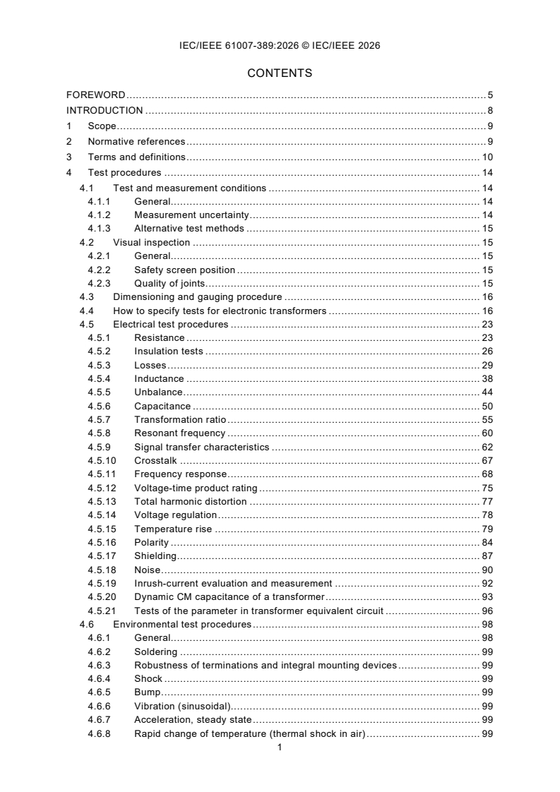
CONTENTS
FOREWORD . 5
INTRODUCTION . 8
1 Scope . 9
2 Normative references . 9
3 Terms and definitions . 10
4 Test procedures . 14
4.1 Test and measurement conditions . 14
4.1.1 General. 14
4.1.2 Measurement uncertainty . 14
4.1.3 Alternative test methods . 15
4.2 Visual inspection . 15
4.2.1 General. 15
4.2.2 Safety screen position . 15
4.2.3 Quality of joints . 15
4.3 Dimensioning and gauging procedure . 16
4.4 How to specify tests for electronic transformers . 16
4.5 Electrical test procedures . 23
4.5.1 Resistance . 23
4.5.2 Insulation tests . 26
4.5.3 Losses . 29
4.5.4 Inductance . 38
4.5.5 Unbalance . 44
4.5.6 Capacitance . 50
4.5.7 Transformation ratio . 55
4.5.8 Resonant frequency . 60
4.5.9 Signal transfer characteristics . 62
4.5.10 Crosstalk . 67
4.5.11 Frequency response . 68
4.5.12 Voltage-time product rating . 75
4.5.13 Total harmonic distortion . 77
4.5.14 Voltage regulation . 78
4.5.15 Temperature rise . 79
4.5.16 Polarity . 84
4.5.17 Shielding . 87
4.5.18 Noise . 90
4.5.19 Inrush-current evaluation and measurement . 92
4.5.20 Dynamic CM capacitance of a transformer . 93
4.5.21 Tests of the parameter in transformer equivalent circuit . 96
4.6 Environmental test procedures . 98
4.6.1 General. 98
4.6.2 Soldering . 99
4.6.3 Robustness of terminations and integral mounting devices . 99
4.6.4 Shock . 99
4.6.5 Bump . 99
4.6.6 Vibration (sinusoidal). 99
4.6.7 Acceleration, steady state . 99
4.6.8 Rapid change of temperature (thermal shock in air) . 99
4.6.9 Sealing . 99
4.6.10 Climatic sequence . 100
4.6.11 Damp heat, steady state . 100
4.6.12 Dry heat . 100
4.6.13 Mould growth . 100
4.6.14 Salt mist, cyclic (sodium chloride solution) . 100
4.6.15 Sulfur dioxide test for contacts and connections . 101
4.6.16 Fire hazard . 101
4.6.17 Immersion in cleaning solvents . 101
4.7 Endurance test procedures . 101
4.7.1 Short-term endurance (load run) . 101
4.7.2 Long-term endurance (life test) . 102
Annex A (normative) DC resistance test . 103
A.1 General . 103
A.2 Resistance values from one ohm to megohms . 104
A.2.1 General. 104
A.2.2 Ammeter and voltmeter method . 104
A.2.3 Substitution method . 105
A.2.4 Wheatstone bridge . 106
A.2.5 Ohmmeter . 107
A.3 Digital ohmmeter – Resistance values from under 1 Ω to many kilo-ohms . 107
Annex B (normative) Dielectric voltage withstand test. 109
Annex C (normative) Induced voltage test . 111
C.1 Induced voltage test . 111
C.2 General test conditions. 111
C.3 General test methods . 111
C.4 Induced excitation voltage and frequency . 113
C.5 Repeated induced voltage testing . 113
C.6 Excitation current. 113
Annex D (normative) Corona test . 114
D.1 Detection of corona . 114
D.2 Analysis of corona . 114
D.3 Detection of corona . 115
Annex E (normative) Quality factor, Q (Damped oscillation method) . 116
E.1 Purpose . 116
E.2 Test principle and equipment . 116
E.3 Procedure . 117
E.4 Calculation . 118
E.5 Information to be stated. 119
Bibliography . 120
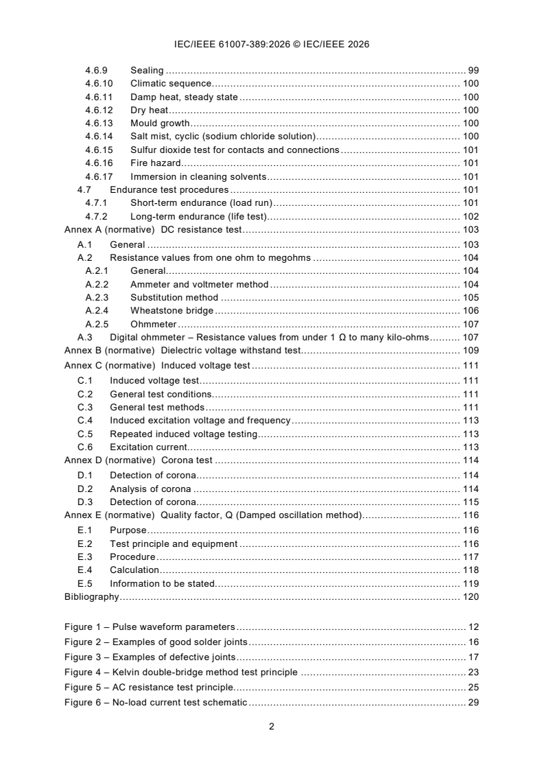
Figure 1 – Pulse waveform parameters . 12
Figure 2 – Examples of good solder joints . 16
Figure 3 – Examples of defective joints . 17
Figure 4 – Kelvin double-bridge method test principle . 23
Figure 5 – AC resistance test principle. 25
Figure 6 – No-load current test schematic . 29
Figure 7 – No-load loss test schematic . 30
Figure 8 – Circuit diagram of resonant bridge schematic . 32
Figure 9 – Circuit magnification of basic measurement method schematic . 32
Figure 10 – Excitation apparent-power measurements test schematic . 33
Figure 11 – Simplified diagram for short-circuit power test . 35
Figure 12 – Diagram of efficiency and power factor measurement . 36
Figure 13 – Test schematic diagram of LCR tester . 38
Figure 14 – Test schematic diagram of impedance analyzer. 38
Figure 15 – Test schematic diagram of incremental inductor test under DC excitation . 40
Figure 16 – Different inductances defined by the magnetic flux linkage Ψ as a function
of current i . 41
Figure 17 – Illustration of energy inductance calculation . 42
Figure 18 – Basic circuit for measuring energy inductance . 43
Figure 19 – Circuit for measuring capacitance unbalance . 45
Figure 20 – Circuit for determining common mode rejection ratio . 46
Figure 21 – Circuit for measuring impedance unbalance . 47
Figure 22 – Circuit for determining crosstalk attenuation. 48
Figure 23 – Measuring techniques for transformer capacitance . 51
Figure 24 – Simplified circuit for transformer capacitance measurement . 51
Figure 25 – Typical graph for determining self-capacitance . 52
Figure 26 – Test circuit for interwinding capacitance measurement . 54
Figure 27 – Circuit for determining inter-winding capacitance . 54
Figure 28 – Diagram of coil voltage and current ratio . 56
Figure 29 – Measuring circuit of transformation ratio by voltage and phase
displacement. 58
Figure 30 – Measuring circuit of transformation ratio by current and phase
displacement. 59
Figure 31 – Circuit for determining parallel self-resonant frequency . 60
Figure 32 – Circuit for determining resonant frequency of resonant assemblies . 61
Figure 33 – Measurement of self-resonance . 62
Figure 34 – Circuit for determination of insertion loss . 63
Figure 35 – Use of two identical transformers when the transformation ratio is not unity
and/or a DC bias is required . 64
Figure 36 – Illustration of return loss . 65
Figure 37 – Basic return loss test circuit . 66
Figure 38 – Circuit diagram for measuring the crossover interference between two
transformer coils . 68
Figure 39 – Impulse waveform measuring circuit . 69
Figure 40 – Test circuit for frequency response measurements . 70
Figure 41 – Test circuit for frequency response measurements with dc current(s) . 70
Figure 42 – Alternate method for frequency response measurements. 72
Figure 43 – Measurement of transformer loss . 72
Figure 44 – Test circuit for low-level pulse response . 74
Figure 45 – Unbiased field and single pulse measurement . 75
Figure 46 – Biased field and repetitive pulse measurement . 75
Figure 47 – Non-linearity of magnetizing current . 76
Figure 48 – Circuit for measuring harmonic distortion . 77
Figure 49 – Voltage regulation test schematic . 78
Figure 50 – How to determine R1 . 79
Figure 51 – Temperature rise measurement circuit by thermo-couple method . 81
Figure 52 – Temperature rise measurement circuit by thermal camera method . 83
Figure 53 – Phase (polarity) test using voltage measurement . 84
Figure 54 – Circuit for bridge measurement of polarity . 85
Figure 55 – Series connection method . 86
Figure 56 – Typical two winding shielded transformer . 87
Figure 57 – Simplified diagram of Figure 56 . 87
Figure 58 – Helmholtz structure . 89
Figure 59 – Dynamic capacitance test of flyback transformers . 94
Figure 60 – Full-bridge topology . 94
Figure 61 – Dynamic capacitance test of transformer in full-bridge circuit . 95
Figure 62 – Equivalent circuit form 1 of non-ideal transformer for magnetic parameter . 96
Figure 63 – Equivalent circuit form 2 of non-ideal transformer for magnetic parameter . 97
Figure A.1 – Measurement of low resistance . 103
Figure A.2 – Ammeter and voltmeter method of resistance measurement . 104
Figure A.3 – Measurement of resistance by substitution . 105
Figure A.4 – Connections of Wheatstone bridge . 106
Figure A.5 – Principle of series ohmmeter . 107
Figure A.6 – Digital ohmmeter method of resistance measurement . 108
Figure B.1 – Typical high-potential test, showing sec 1 under test . 109
Figure B.2 – Typical high-potential test of inductor . 109
Figure C.1 – Block diagram of induced voltage surge test . 111
Figure D.1 – Typical circuit for corona measurement (circuit 1) . 114
Figure D.2 – Typical circuit for corona measurement (circuit 2) . 115
Figure E.1 – Damping oscillation method schematic . 116
Figure E.2 – Oscilloscope sweep frequency of damping oscillation method schematic . 117
Table 1 – Recommended tests and specifications for specific transformer and inductor
groups . 18
Table 2 – Voltage of dielectric withstanding voltage test . 26
Table 3 – Cube dimensions, together with corresponding search coil data . 90
Table 4 – Sound-level corrections for noise tests . 91
Table 5 – Residual flux density maximum . 93
Transformers and inductors for use in electronic
and telecommunication equipment -
Part 389: Measuring methods and test procedures
FOREWORD
1) The International Electrotechnical Commission (IEC) is a worldwide organization for standardization comprising
all national electrotechnical committees (IEC National Committees). The object of IEC is to promote international
co-operation on all questions concerning standardization in the electrical and electronic fields. To this end and
in addition to other activities, IEC publishes International Standards, Technical Specifications, Technical Reports,
Publicly Available Specifications (PAS) and Guides (hereafter referred to as "IEC document(s)"). Their
preparation is entrusted to technical committees; any IEC National Committee interested in the subject dealt with
may participate in this preparatory work. International, governmental and non-governmental organizations liaising
with the IEC also participate in this preparation.
IEEE Standards documents are developed within IEEE Societies and subcommittees of IEEE Standards
Association (IEEE SA) Board of Governors. IEEE develops its standards through an accredited consensus
development process, which brings together volunteers representing varied viewpoints and interests to achieve
the final product. IEEE standards are documents developed by volunteers with scientific, academic, and industry-
based expertise in technical working groups. Volunteers are not necessarily members of IEEE or IEEE SA and
participate without compensation from IEEE. While IEEE administers the process and establishes rules to promote
fairness in the consensus development process, IEEE does not independently evaluate, test, or verify the
accuracy of any of the information or the soundness of any judgments contained in its standards.
IEEE documents are made available for use subject to important notices and legal disclaimers (see
https://standards.ieee.org/ipr/disclaimers.html for more information).
IEC collaborates closely with IEEE in accordance with conditions determined by agreement between the two
organizations. This Dual Logo International Standard was jointly developed by the IEC and IEEE under the terms
of that agreement.
2) The formal decisions of IEC on technical matters express, as nearly as possible, an international consensus of
opinion on the relevant subjects since each technical committee has representation from all interested IEC
National Committees. The formal decisions of IEEE on technical matters, once consensus within IEEE Societies
and Standards Coordinating Committees has been reached, is determined by a balanced ballot of materially
interested parties who indicate interest in reviewing the proposed standard. Final approval of the IEEE standards
document is given by the IEEE Standards Association (IEEE SA) Standards Board.
3) IEC/IEEE Publications have the form of recommendations for international use and are accepted by IEC National
Committees/IEEE Societies in that sense. While all reasonable efforts are made to ensure that the technical
content of IEC/IEEE Publications is accurate, IEC or IEEE cannot be held responsible for the way in which they
are used or for any misinterpretation by any end user.
4) In order to promote international uniformity, IEC National Committees undertake to apply IEC Publications
(including IEC/IEEE Publications) transparently to the maximum extent possible in their national and regional
publications. Any divergence between any IEC/IEEE Publication and the corresponding national or regional
publication shall be clearly indicated in the latter.
5) IEC and IEEE do not provide any attestation of conformity. Independent certification bodies provide conformity
assessment services and, in some areas, access to IEC marks of conformity. IEC and IEEE are not responsible
for any services carried out by independent certification bodies.
6) All users should ensure that they have the latest edition of this publication.
7) No liability shall attach to IEC or IEEE or their directors, employees, servants or agents including individual
experts and members of technical committees and IEC National Committees, or volunteers of IEEE Societies and
the Standards Coordinating Committees of the IEEE Standards Association (IEEE SA) Standards Board, for any
personal injury, property damage or other damage of any nature whatsoever, whether direct or indirect, or for
costs (including legal fees) and expenses arising out of the publication, use of, or reliance upon, this IEC/IEEE
Publication or any other IEC or IEEE Publications.
8) Attention is drawn to the normative references cited in this publication. Use of the referenced publications is
indispensable for the correct application of this publication.
9) Attention is drawn to the possibility that implementation of this IEC/IEEE Publication may require use of material
covered by patent rights. By publication of this standard, no position is taken with respect to the existence or
validity of any patent rights in connection therewith. IEC or IEEE shall not be held responsible for identifying
Essential Patent Claims for which a license may be required, for conducting inquiries into the legal validity or
scope of Patent Claims or determining whether any licensing terms or conditions provided in connection with
submission of a Letter of Assurance, if any, or in any licensing agreements are reasonable or non-discriminatory.
Users of this standard are expressly advised that determination of the validity of any patent rights, and the risk
of infringement of such rights, is entirely their own responsibility.
IEC/IEEE 61007-389 was prepared by IEC technical committee 51: Magnetic components,
ferrite and magnetic powder materials, in cooperation with Standards Committee of the IEEE
Power Electronics Society, under the IEC/IEEE Dual Logo Agreement between IEC and IEEE.
It is an International Standard.
This document is published as an IEC/IEEE Dual Logo standard.
This first edition of IEC/IEEE 61007-389 cancels and replaces IEC 61007:2020 and
IEEE 389:2020, which has been technically revised.
This edition includes the following significant technical changes with respect to the previous
edition:
a) added the following new test items:
1) transformer capacitance (in 4.5.6.1);
2) voltage transformation (VT) ratio (in 4.5.7.3);
3) thermo-couple method (in 4.5.15.3);
4) bridge circuit measurement (in 4.5.16.3);
5) dynamic CM capacitance of a transformer (in 4.5.20);
6) tests of the parameter in transformer equivalent circuit (in 4.5.21);
b) updated the following test items:
1) added test purpose: AC resistance (in 4.5.1.2); dielectric withstand voltage test (in
4.5.2.1); effective inductance (in 4.5.4.1); capacitance unbalance (in 4.5.5.1); total
harmonic distortion (in 4.5.13);
2) testing fundamentals and equipment modification: DC winding resistance (in 4.5.1.1);
AC resistance (in 4.5.1.2); winding continuity (in 4.5.1.3); excitation apparent-power
measurements (in 4.5.3.4); capacitance unbalance (in 4.5.5.1); self-capacitance
(distributed capacitance) (in 4.5.6.2); inter-winding capacitance (in 4.5.6.3); inherent
self-resonance (in 4.5.8.1); resonant assemblies (in 4.5.8.2); insertion loss (in 4.5.9.1);
return loss (in 4.5.9.2); crosstalk (in 4.5.10); pulse characteristics (in 4.5.11.1);
transformer response measurements (in 4.5.11.2); total harmonic distortion (in 4.5.13);
method utilizing the change in DC resistance of a winding (in 4.5.15.1); method using
an additional series-opposing bifilar winding (in 4.5.15.2); safety screens (in 4.5.17.2);
magnetic radiation (in 4.5.17.4); acoustic noise (in 4.5.18.1);
3) procedure modification: dielectric withstand voltage test (in 4.5.2.1); induced voltage
test (in 4.5.2.2); capacitance unbalance (in 4.5.5.1);
4) Information to be stated modification: insulation resistance (in 4.5.2.4); excitation
apparent-power measurements (in 4.5.3.4); stray-load losses (in 4.5.3.5); power factor
(in 4.5.3.8); inherent self-resonance (in 4.5.8.1); parallel resonance and series
resonance (in 4.5.8.3); transformer pulse response (in 4.5.11.3);
c) removed Annex D and Annex F in IEC 61007:2020.
The text of this International Standard is based on the following IEC documents:
Draft Report on voting
51/1612/FDIS 51/1627/RVD
Full information on the voting for its approval can be found in the report on voting indicated in
the above table.
The language used for the development of this International Standard is English.
This document was drafted in accordance with the rules given in the ISO/IEC Directives, Part 2,
available at www.iec.ch/members_experts/refdocs. The main document types developed by IEC
are described in greater detail at www.iec.ch/publications/.
A list of all parts in the IEC 61007 series, published under the general title Transformers and
inductors for use in electronic and telecommunication equipment, can be found on the IEC
website.
The IEC Technical Committee and IEEE Technical Committee have decided that the contents
of this document will remain unchanged until the stability date indicated on the IEC website
under webstore.iec.ch in the data related to the specific document. At this date, the document
will be
– reconfirmed,
– withdrawn, or
– revised.
INTRODUCTION
IEC 61007 describes a number of tests to determine the important parameters and performance
characteristics of transformers and inductors used in electronic and telecommunications
equipment, aiming to check whether the product meets specific applications and is widely used
in industrial manufacturing processes and customer acceptance tests. It includes the test
method of electrical testing such as resistance strength, power loss, impedance, inductance
value and quality factor, including the test purpose, test procedure and test principle, as well
as the reliability test items for electronic transformers and inductors. IEEE Std 389:2020
specifies test and experimental methods applicable to the performance evaluation of electronic
transformers and inductors, for the test and evaluation of transformers with lower power ratings
(communications, instrumentation, control, small appliance and computer applications). It
includes electrical strength, power loss, inductance, impedance and other test items, Kelvin
bridge method, impedance bridge method and other measurement methods, but does not
include reliability test items and test procedures.
Both documents cover test methods and procedures for electronic transformers and inductors,
but they have different emphases and test methods, which bring a lot of inconvenience to users.
There is a growing call for establishing an efficient and streamlined universal international
standard to meet the needs of developers, customers and the market. Therefore, a proposal for
a dual label (IEC/IEEE) standard is formulated to combine IEC 61007 and IEEE Std 389:2020
into one unified new standard.
The structural expression of this document refers to IEC 61007, and on this basis, the
expression of test principles, test procedures and test conditions is added for each test item.
This document is a combined and shared standard.
1 Scope
This document describes a number of tests for use in determining the significant parameters
and performance characteristics of transformers and inductors for use in electronics and
telecommunication equipment. These test methods are designed primarily for transformers and
inductors used in all types of electronics applications that can be involved in any specification
for such components. Even though these tests could be applied supplementally for other types
of transformers, such as those with larger power ratings used in the utility power industry, the
tests discussed in this document are not intended to replace the tests in standards for those
other transformers.
Some of the tests described are intended for qualifying a product for a specific application,
while others are test practices used for manufacturing and customer acceptance testing. The
test methods described here include those parameters most commonly used in the electronics
transformer and inductor industry: electric strength, resistance, power loss, inductance,
impedance, balance, transformation ratio and many others used less frequently.
2 Normative references
The following documents are referred to in the text in such a way that some or all of their content
constitutes requirements of this document. For dated references, only the edition cited applies.
For undated references, the latest edition of the referenced document (including any
amendments) applies.
IEC 60050 (all parts), International Electrotechnical Vocabulary (IEV), available at
https://www.electropedia.org
IEC 60068-1:2013, Environmental testing - Part 1: General and guidance
IEC 60068-2-1, Environmental testing - Part 2-1: Tests - Test A: Cold
IEC 60068-2-2, Environmental testing - Part 2-2: Tests - Test B: Dry heat
IEC 60068-2-6, Environmental testing - Part 2-6: Tests - Test Fc: Vibration (sinusoidal)
IEC 60068-2-7, Basic environmental testing procedures - Part 2-7: Tests - Test Ga and
guidance: Acceleration, steady state
IEC 60068-2-10, Environmental testing - Part 2-10: Tests - Test J and guidance: Mould growth
IEC 60068-2-13, Environmental testing - Part 2-13: Tests - Test M: Low air pressure
IEC 60068-2-14, Environmental testing - Part 2-14: Tests - Test N: Change of temperature
IEC 60068-2-17, Environmental testing - Part 2-17: Tests - Test Q: Sealing
IEC 60068-2-20, Environmental testing - Part 2-20: Tests - Test Ta and Tb: Test methods for
solderability and resistance to soldering heat of devices with leads
IEC 60068-2-21, Environmental testing - Part 2-21: Tests - Test U: Robustness of terminations
and integral mounting devices
IEC 60068-2-27, Environmental testing - Part 2-27: Tests - Test Ea and guidance: Shock
IEC 60068-2-30, Environmental testing - Part 2-30: Tests - Test Db: Damp heat, cyclic
(12 h + 12 h cycle)
IEC 60068-2-42, Environmental testing - Part 2-42: Tests - Test Kc: Sulphur dioxide test for
contacts and connections
IEC 60068-2-45, Basic environmental testing procedures - Part 2-45: Tests - Test XA and
guidance: Immersion in cleaning solvents
IEC 60068-2-52, Environmental testing - Part 2-52: Tests - Test Kb: Salt mist, cyclic (sodium
chloride solution)
IEC 60068-2-78, Environmental testing - Part 2-78: Tests - Test Cab: Damp heat, steady state
IEC 60695-11-2, Fire hazard testing - Part 11-2: Test flames - 1 kW pre-mixed flame -
Apparatus, confirmatory test arrangement and guidance
IEC 60695-11-5, Fire hazard testing - Part 11-5: Test flames - Needle-flame test method -
Apparatus, confirmatory test arrangement and guidance
IEC 61672-1, Electroacoustics - Sound level meters - Part 1: Specifications
IEC 62024-2, High frequency inductive components - Electrical characteristics and measuring
methods - Part 2: Rated current of inductors for DC-to-DC converters
IEC 62044-2, Cores made of soft magnetic materials - Measuring methods - Part 2: Magnetic
properties at low excitation level
3 Terms and definitions
For the purposes of this document, the terms and definitions given in IEC 60050 (all parts) and
the following apply.
ISO and IEC maintain terminology databases for use in standardization at the following
addresses:
– IEC Electropedia: available at https://www.electropedia.org/
– ISO Online browsing platform: available at https://www.iso.org/obp
– IEEE Standards Dictionary Online: available at https://dictionary.ieee.org
– Electrical and magnetic terms used in this recommended practice are in accordance with
those given in IEEE Standards Dictionary Online. Certain parameters and symbols of
particular significance in the evaluation of electronics transformers are given where required
in the text.
3.1
component
part of a device that cannot be divided into smaller parts without losing their specific functions
Note 1 to entry: The components mentioned in this file refer to transformers or inductors.
3.2
peak working voltage
maximum instantaneous voltage for which the winding insulation is rated under working circuit
conditions
3.3 Pulse wave form parameters (see Figure 1)
3.3.1
peak pulse amplitude
U
m
maximum value of an extrapolated smooth curve through the top of the pulse, excluding any
initial "spike" or "overshoot", the duration of which is less than 10 % of the pulse duration
3.3.2
pulse duration
t
d
time interval between the first and last instant at which the pulse amplitude equals 50 % of the
peak pulse amplitude
3.3.3
pulse rise time
t
r
interval between the first instant at which the pulse amplitude reaches 10 % of the peak pulse
amplitude and the first instant at which the pulse amplitude reaches 90 % of the peak pulse
amplitude, excluding an unwanted or irrelevant portion of the waveform
3.3.4
pulse fall time
t
f
interval between the last instant at which the pulse amplitude reaches 90 % of the peak pulse
amplitude and the next instant at which the pulse amplitude reaches 10 % of the peak pulse
amplitude excluding any unwanted or irrelevant portion of the waveform
Note 1 to entry: Where the value of the droop approaches 10 % of the peak pulse amplitude, the upper point defining
fall time can be replaced by the last instant at which the pulse amplitude reaches 80 % of the peak pulse amplitude.
3.3.5
droop
difference between the peak pulse amplitude and the amplitude of the extrapolated smooth
curve through the top of the pulse, excluding any initial "spike" of "overshoot", at its intersection
with the straight line through the points defining the pulse fall time, expressed as a percentage
of the peak pulse amplitude
3.3.6
overshoot
amount by which the pulse crest (the maximum amplitude of the pulse) exceeds the peak pulse
amplitude, expressed as a percentage of the peak pulse amplitude
3.3.7
recovery time
time interval between the end of the pulse fall time and the time at which the pulse amplitude
last reaches 10 % of the peak pulse amplitude
Note 1 to entry: Exceptionally, a value of less than 10 % may be used, in which case the interval is termed "the
X % recovery time".
3.3.8
pulse repetition frequency
average number of pulses in unit time independent of the period over which it is measured
NOTE 1 Leading edge: the interval between the first instant at which the pulse amplitude begins and the first instant
at which the pulse amplitude reaches the peak pulse amplitude.
NOTE 2 Pulse top: the interval between the first instant at which the pulse amplitude equals the peak pulse
amplitude and the last instant at which the pulse amplitude equals 90 % of the peak pulse amplitude.
NOTE 3 Trailing edge: the interval between the last instant at which the pulse amplitude equals 90 % of the peak
pulse amplitude and the first instant at which the pulse amplitude of the second cycle begins.
NOTE 4 For clarity in illustrating droop, the 80 % and 10 % points have been used in constructing the line which
determines the border between the pulse top and the trailing edge.
Figure 1 – Pulse waveform parameters
3.4
quality factor
Q factor
ratio of the energy stored to the energy dissipated during one cycle at a particular frequency in
a specified winding
Note 1 to entry: The Q factor is expressed in terms of either the series or the parallel components of reactance and
loss resistance.
3.5
harmonic distortion
square root of the sum of the square of all harmonic voltages up to and including the seventh
harmonic (excluding the fundamental) expressed as a percentage or as a ratio in decibels of
the fundamental
3.6
winding temperature
mean temperature rise of any winding of the component under full load at ambient temperature,
when thermal stability has been achieved, added to the specified ambient temperature
3.7
voltage-time product rating
voltage pulse amplitude multiplied by the time interval between the first and last instants at
which the pulse amplitude equals 50 % of the peak pulse amplitude
Note 1 to entry: The start of the pulse within which the non–linearity of the magnetizing current does not exceed a
specified value.
3.8
background noise
acoustic noise
noise measured at a measuring point with the component under test not electrically excited
3.9 Current transformer parameters
3.9.1
current transformation ratio
k
ratio of the RMS value of the primary current to the RMS value of the secondary current under
specified conditions
Note 1 to entry: The opposite of current transformation ratio is turn ratio.
3.9.2
phase angle
angular displacement of the fundamental frequency between the vector representing the
primary and secondary currents of
...