

SIST EN 301 842-2 V1.6.1:2011
(Main)VHF air-ground Digital Link (VDL) Mode 4 radio equipment - Technical characteristics and methods of measurement for ground-based equipment - Part 2: General description and data link layer
- Abstract
The present document applies to the following radio equipment types:
Very High Frequency (VHF) Digital Link (VDL) Mode 4 ground-based radio transmitters and receivers for air-ground communications operating in the VHF band, using Gaussian-filtered Frequency Shift Keying (GFSK) Modulation with 25 kHz channel spacing and capable of tuning to any of the 25 kHz channels from 118,000 MHz to 136,975 MHz as defined in ICAO VHF Digital Link (VDL) Standards and Recommended Practices (SARPs) [i.4].
The present document provides part 2 of the technical specifications.
The present document is designed to ensure that equipment certified to it will be compatible with the relevant ICAO VDL SARPs [i.4] and ICAO VDL4 Technical Manual [i.1].
Manufacturers should note that in future the tuning range for the ground transceivers may also cover any 25 kHz channel from 108,000 MHz to 117,975 MHz.
The scope of the present document is limited to ground stations. The equivalent specification for airborne stations is EN 302 842 [10], [11], [12] and [13].
The VDL Mode 4 system provides data communication exchanges between aircraft and ground based systems supporting surveillance and communication applications. The supported modes of communication include:
broadcast and point-to-point communication;
broadcast services including Automatic Dependent Surveillance-Broadcast (ADS-B), Traffic Information Service-Broadcast (TIS-B) and Flight Information Service-Broadcast (FIS-B) capabilities;
air-to-air, air-to-ground, ground-to-air and ground mobile services;
operation without ground infrastructure.
VDL Mode 4 is designed to be an Air/Ground subsystem of the Aeronautical Telecommunication Network (ATN) [i.2] using the AM(R)S band and it is organized according to the Open Systems Interconnection (OSI) model (defined by ISO). It provides reliable sub network services to the ATN system. Other networks can also be supported but these have not been focussed on in the present document.
The present document specifies functional specifications of VHF communication ground station equipment intended to be used for air-ground and air-air data communications. The present document is derived from the standards and specifications in:
VDL Mode 4 standards produced under the auspices of the International Civil Aviation
Organization (ICAO) [i.1].
Other relevant standards as defined in clause 2.
It is envisaged that manufacturers may provide equipment supporting:
broadcast services only;
point-to-point services only;
both broadcast and point-to-point services.
EN 301 842-1 [3] deals with tests of the physical layer. The present document defines the core link layer requirements for the VDL Mode 4 ground station necessary to support all types of equipment. This includes a simple position broadcast functionality.
The present document deals with tests of the link layer sufficient to support core link layer functionality, and it also includes requirements and tests sufficient to recognize and respond to transmissions associated with point-to-point communication. The present document does not address requirements for the full ADS-B message set, or for other broadcast applications that can be supported by the VDL Mode 4 equipment. These are covered by EN 301 842-3 [7].
Detailed requirements for point-to-point communication are beyond the scope of the present document, but can be found in EN 301 842-4 [8]. EN 301 842-4 [8] also includes the interface to the Aeronautical Telecommunication Network (ATN) as defined in ATN SARPs [i.2].
As the measured values of equipment performance may be a function of the method of measurement, standard test conditions and methods of test are recommended in the present document.
- Status
- Published
- Public Enquiry End Date
- 28-Feb-2011
- Publication Date
- 16-Oct-2011
- Technical Committee
- MOC - Mobile Communications
- Current Stage
- 6060 - National Implementation/Publication (Adopted Project)
- Start Date
- 04-Oct-2011
- Due Date
- 09-Dec-2011
- Completion Date
- 17-Oct-2011
Buy Documents
en_30184202v010601c - VHF air-ground Digital Link (VDL) Mode 4 radio equipment; Technical characteristics and methods of measurement for ground-based equipment; Part 2: General description and data link layer
en_30184202v010601p - VHF air-ground Digital Link (VDL) Mode 4 radio equipment; Technical characteristics and methods of measurement for ground-based equipment; Part 2: General description and data link layer
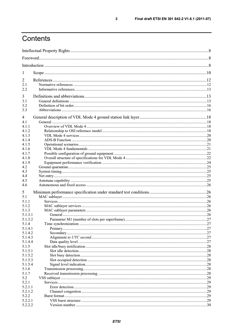
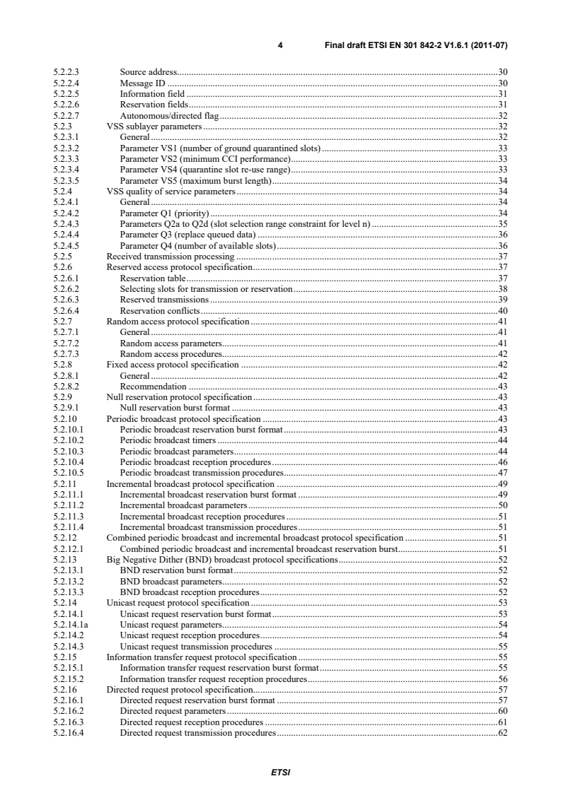
en_30184202v010601v - VHF air-ground Digital Link (VDL) Mode 4 radio equipment; Technical characteristics and methods of measurement for ground-based equipment; Part 2: General description and data link layer

SIST EN 301 842-2 V1.6.1:2011 is the Slovenian adoption of the ETSI standard for VHF air-ground Digital Link (VDL) Mode 4 ground-based radio equipment. It specifies the general description, data link layer behavior, and protocol test methods for ground stations used in aeronautical air-ground communications, so manufacturers, test laboratories, and certification bodies can assess compatibility and performance.
What does SIST EN 301 842-2 V1.6.1:2011 specify?
SIST EN 301 842-2 V1.6.1:2011 applies to VDL Mode 4 ground-based transmitters and receivers for air-ground communications in the VHF band. The equipment uses Gaussian-filtered Frequency Shift Keying (GFSK) modulation, 25 kHz channel spacing, and tuning across 118,000 MHz to 136,975 MHz.
The document is limited to ground stations. It is organized into general scope, references, definitions, the link-layer description, minimum performance requirements, general design requirements, and protocol test procedures, followed by informative annexes.
| Annex | What it covers |
|---|---|
| Annex A | Cross reference matrix |
| Annex B | Description of ISO/IEC 9646 test methodology |
| Annex C | Bibliography |
What are the key requirements of SIST EN 301 842-2 V1.6.1:2011?
Clause 4 describes VDL Mode 4 as an Air/Ground subsystem of the Aeronautical Telecommunication Network (ATN) organized according to the Open Systems Interconnection (OSI) model. In practice, this means the station must fit a layered network model and support broadcast, point-to-point, and air-ground data exchange.
Clause 5.1 defines the MAC sublayer services, timing, slot idle/busy/occupied detection, signal level indication, and transmission and received transmission processing. These functions matter because they control when a station may talk and how it recognizes usable or occupied slots.
Clause 5.2 defines the VSS sublayer, including burst structure, version number, source address, message ID, information field, reservation fields, and the autonomous/directed flag. It also specifies the access protocols for reserved, random, fixed, null reservation, periodic broadcast, incremental broadcast, BND broadcast, unicast request, information transfer request, directed request, block reservation, response, general request, general response, and retransmission.
Clause 5.3 covers the DLS sublayer, including data transfer, station address encoding, DLS burst formats, and parameter ND4, which sets the maximum length of a UDATA burst. For users, this is the data carriage part of the link.
Clause 5.4 covers the Link Management Entity (LME) sublayer, including synchronization burst formats, control (CTRL) parameter formats, timers, synchronization burst procedures, Peer Entity Contact Table (PECT), network entry, and additional material for ADS-B applications. This is the part that keeps the station synchronized and able to join and manage the network.
Clause 5.5 adds ground-station requirements such as maintenance of Primary time, coordination, network timing, application interface behavior, transmission control, superframe block reservation rebroadcast, protection of fixed access transmissions, autotune restrictions, transmission timing for autotune reservations, and channel-usage reporting. These requirements are important for real installations because they link the radio behavior to system operation.
Clause 5.6 defines compact position reporting, including symbols, data types, constants, variables, functions, patch constants, and position encoding and decoding. That material supports position-reporting applications without requiring readers to derive the format themselves.
Clause 6 covers controls and indicators, warm up, software management, recovery from failure, and monitoring of proper operation. Clause 7 then turns the specification into testable requirements with standard test conditions, a required test rig, test-suite methodology, and detailed protocol test cases.
What terms does SIST EN 301 842-2 V1.6.1:2011 define?
- VDL Mode 4 - The VHF Digital Link mode covered by the document for air-ground and related data communications.
- GFSK - Gaussian-filtered Frequency Shift Keying, the modulation used by the radio equipment.
- ADS-B - Automatic Dependent Surveillance-Broadcast, a broadcast service supported by the system.
- ATN - Aeronautical Telecommunication Network, the network context in which VDL Mode 4 is organized.
- MAC sublayer - The medium access part that handles slot timing, channel access, and transmission processing.
- VSS sublayer - The VDL system signalling part that carries reservation, request, broadcast, and response bursts.
- LME - Link Management Entity, the part that manages synchronization, network entry, and related control functions.
- DLS sublayer - The data link service part that handles data transfer and address encoding.
Who uses SIST EN 301 842-2 V1.6.1:2011?
This standard is used by manufacturers of VDL Mode 4 ground stations, transceivers, and receivers. It is also used by test laboratories that run protocol and performance tests, and by certification or approval bodies that assess whether equipment matches the required behavior.
It is relevant to aeronautical communication integrators, airport or network operators, and quality managers who need to verify timing, access behavior, broadcast support, and ground-station coordination. Buyers use it to compare equipment on a common technical basis.
Which standards are used with SIST EN 301 842-2 V1.6.1:2011?
- ICAO VHF Digital Link (VDL) Standards and Recommended Practices (SARPs) - The technical and operational basis for the VDL Mode 4 channel and behavior.
- ICAO VDL4 Technical Manual - Provides the companion technical guidance the document is aligned with.
- EN 301 842-1 - Covers testing of the physical layer.
- EN 301 842-3 - Covers additional broadcast aspects.
- EN 301 842-4 - Covers point-to-point functions and the ATN interface.
- EN 302 842 - The equivalent airborne specification for the same VDL Mode 4 family.
- EN 301 489-22 - The EMC compliance context named in the introduction.
- ISO/IEC 9646 - The test methodology framework explained in Annex B.
What does the SIST EN 301 842-2 V1.6.1:2011 document contain?
SIST EN 301 842-2 V1.6.1:2011 contains detailed link-layer behavior for VDL Mode 4 ground stations, including state, timing, burst formats, and access procedures. It includes parameter tables, reservation logic, broadcast and request procedures, and compact position reporting definitions.
It also contains general design requirements for the equipment and a large protocol test section with test-suite structure, declarations, constraints, macros, and case descriptions. The tests use RF and VSS interactions, slot timing observations, and statistical checks to confirm behavior.
Annex A provides a cross reference matrix, Annex B explains the ISO/IEC 9646 test-suite approach, and Annex C gives the bibliography.
Buy Documents
en_30184202v010601c - VHF air-ground Digital Link (VDL) Mode 4 radio equipment; Technical characteristics and methods of measurement for ground-based equipment; Part 2: General description and data link layer
en_30184202v010601p - VHF air-ground Digital Link (VDL) Mode 4 radio equipment; Technical characteristics and methods of measurement for ground-based equipment; Part 2: General description and data link layer
en_30184202v010601v - VHF air-ground Digital Link (VDL) Mode 4 radio equipment; Technical characteristics and methods of measurement for ground-based equipment; Part 2: General description and data link layer
Get Certified
Connect with accredited certification bodies for this standard

BSI Group
BSI (British Standards Institution) is the business standards company that helps organizations make excellence a habit.

BUREAU VERITAS Certification Germany
Bureau Veritas certification in Germany.

Element Materials Technology
Materials testing and product certification.
Sponsored listings
Frequently Asked Questions
SIST EN 301 842-2 V1.6.1:2011 is a standard published by the Slovenian Institute for Standardization (SIST). Its full title is "VHF air-ground Digital Link (VDL) Mode 4 radio equipment - Technical characteristics and methods of measurement for ground-based equipment - Part 2: General description and data link layer". This standard covers: The present document applies to the following radio equipment types: Very High Frequency (VHF) Digital Link (VDL) Mode 4 ground-based radio transmitters and receivers for air-ground communications operating in the VHF band, using Gaussian-filtered Frequency Shift Keying (GFSK) Modulation with 25 kHz channel spacing and capable of tuning to any of the 25 kHz channels from 118,000 MHz to 136,975 MHz as defined in ICAO VHF Digital Link (VDL) Standards and Recommended Practices (SARPs) [i.4]. The present document provides part 2 of the technical specifications. The present document is designed to ensure that equipment certified to it will be compatible with the relevant ICAO VDL SARPs [i.4] and ICAO VDL4 Technical Manual [i.1]. Manufacturers should note that in future the tuning range for the ground transceivers may also cover any 25 kHz channel from 108,000 MHz to 117,975 MHz. The scope of the present document is limited to ground stations. The equivalent specification for airborne stations is EN 302 842 [10], [11], [12] and [13]. The VDL Mode 4 system provides data communication exchanges between aircraft and ground based systems supporting surveillance and communication applications. The supported modes of communication include: broadcast and point-to-point communication; broadcast services including Automatic Dependent Surveillance-Broadcast (ADS-B), Traffic Information Service-Broadcast (TIS-B) and Flight Information Service-Broadcast (FIS-B) capabilities; air-to-air, air-to-ground, ground-to-air and ground mobile services; operation without ground infrastructure. VDL Mode 4 is designed to be an Air/Ground subsystem of the Aeronautical Telecommunication Network (ATN) [i.2] using the AM(R)S band and it is organized according to the Open Systems Interconnection (OSI) model (defined by ISO). It provides reliable sub network services to the ATN system. Other networks can also be supported but these have not been focussed on in the present document. The present document specifies functional specifications of VHF communication ground station equipment intended to be used for air-ground and air-air data communications. The present document is derived from the standards and specifications in: VDL Mode 4 standards produced under the auspices of the International Civil Aviation Organization (ICAO) [i.1]. Other relevant standards as defined in clause 2. It is envisaged that manufacturers may provide equipment supporting: broadcast services only; point-to-point services only; both broadcast and point-to-point services. EN 301 842-1 [3] deals with tests of the physical layer. The present document defines the core link layer requirements for the VDL Mode 4 ground station necessary to support all types of equipment. This includes a simple position broadcast functionality. The present document deals with tests of the link layer sufficient to support core link layer functionality, and it also includes requirements and tests sufficient to recognize and respond to transmissions associated with point-to-point communication. The present document does not address requirements for the full ADS-B message set, or for other broadcast applications that can be supported by the VDL Mode 4 equipment. These are covered by EN 301 842-3 [7]. Detailed requirements for point-to-point communication are beyond the scope of the present document, but can be found in EN 301 842-4 [8]. EN 301 842-4 [8] also includes the interface to the Aeronautical Telecommunication Network (ATN) as defined in ATN SARPs [i.2]. As the measured values of equipment performance may be a function of the method of measurement, standard test conditions and methods of test are recommended in the present document.
The present document applies to the following radio equipment types: Very High Frequency (VHF) Digital Link (VDL) Mode 4 ground-based radio transmitters and receivers for air-ground communications operating in the VHF band, using Gaussian-filtered Frequency Shift Keying (GFSK) Modulation with 25 kHz channel spacing and capable of tuning to any of the 25 kHz channels from 118,000 MHz to 136,975 MHz as defined in ICAO VHF Digital Link (VDL) Standards and Recommended Practices (SARPs) [i.4]. The present document provides part 2 of the technical specifications. The present document is designed to ensure that equipment certified to it will be compatible with the relevant ICAO VDL SARPs [i.4] and ICAO VDL4 Technical Manual [i.1]. Manufacturers should note that in future the tuning range for the ground transceivers may also cover any 25 kHz channel from 108,000 MHz to 117,975 MHz. The scope of the present document is limited to ground stations. The equivalent specification for airborne stations is EN 302 842 [10], [11], [12] and [13]. The VDL Mode 4 system provides data communication exchanges between aircraft and ground based systems supporting surveillance and communication applications. The supported modes of communication include: broadcast and point-to-point communication; broadcast services including Automatic Dependent Surveillance-Broadcast (ADS-B), Traffic Information Service-Broadcast (TIS-B) and Flight Information Service-Broadcast (FIS-B) capabilities; air-to-air, air-to-ground, ground-to-air and ground mobile services; operation without ground infrastructure. VDL Mode 4 is designed to be an Air/Ground subsystem of the Aeronautical Telecommunication Network (ATN) [i.2] using the AM(R)S band and it is organized according to the Open Systems Interconnection (OSI) model (defined by ISO). It provides reliable sub network services to the ATN system. Other networks can also be supported but these have not been focussed on in the present document. The present document specifies functional specifications of VHF communication ground station equipment intended to be used for air-ground and air-air data communications. The present document is derived from the standards and specifications in: VDL Mode 4 standards produced under the auspices of the International Civil Aviation Organization (ICAO) [i.1]. Other relevant standards as defined in clause 2. It is envisaged that manufacturers may provide equipment supporting: broadcast services only; point-to-point services only; both broadcast and point-to-point services. EN 301 842-1 [3] deals with tests of the physical layer. The present document defines the core link layer requirements for the VDL Mode 4 ground station necessary to support all types of equipment. This includes a simple position broadcast functionality. The present document deals with tests of the link layer sufficient to support core link layer functionality, and it also includes requirements and tests sufficient to recognize and respond to transmissions associated with point-to-point communication. The present document does not address requirements for the full ADS-B message set, or for other broadcast applications that can be supported by the VDL Mode 4 equipment. These are covered by EN 301 842-3 [7]. Detailed requirements for point-to-point communication are beyond the scope of the present document, but can be found in EN 301 842-4 [8]. EN 301 842-4 [8] also includes the interface to the Aeronautical Telecommunication Network (ATN) as defined in ATN SARPs [i.2]. As the measured values of equipment performance may be a function of the method of measurement, standard test conditions and methods of test are recommended in the present document.
SIST EN 301 842-2 V1.6.1:2011 is classified under the following ICS (International Classification for Standards) categories: 33.060.99 - Other equipment for radiocommunications; 35.100.20 - Data link layer; 49.090 - On-board equipment and instruments. The ICS classification helps identify the subject area and facilitates finding related standards.
SIST EN 301 842-2 V1.6.1:2011 is associated with the following European legislation: EU Directives/Regulations: TRRTP124. When a standard is cited in the Official Journal of the European Union, products manufactured in conformity with it benefit from a presumption of conformity with the essential requirements of the corresponding EU directive or regulation.
SIST EN 301 842-2 V1.6.1:2011 is available in PDF format for immediate download after purchase. The document can be added to your cart and obtained through the secure checkout process. Digital delivery ensures instant access to the complete standard document.
Standards Content (Sample)
Draft ETSI EN 301 842-2 V1.6.1 (2010-12)
European Standard (Telecommunications series)
VHF air-ground Digital Link (VDL) Mode 4 radio equipment;
Technical characteristics and methods of measurement
for ground-based equipment;
Part 2: General description and data link layer
2 Draft ETSI EN 301 842-2 V1.6.1 (2010-12)
Reference
REN/AERO-00006-2
Keywords
aeronautical, digital, radio, testing, VHF
ETSI
650 Route des Lucioles
F-06921 Sophia Antipolis Cedex - FRANCE
Tel.: +33 4 92 94 42 00 Fax: +33 4 93 65 47 16
Siret N° 348 623 562 00017 - NAF 742 C
Association à but non lucratif enregistrée à la
Sous-Préfecture de Grasse (06) N° 7803/88
Important notice
Individual copies of the present document can be downloaded from:
http://www.etsi.org
The present document may be made available in more than one electronic version or in print. In any case of existing or
perceived difference in contents between such versions, the reference version is the Portable Document Format (PDF).
In case of dispute, the reference shall be the printing on ETSI printers of the PDF version kept on a specific network drive
within ETSI Secretariat.
Users of the present document should be aware that the document may be subject to revision or change of status.
Information on the current status of this and other ETSI documents is available at
http://portal.etsi.org/tb/status/status.asp
If you find errors in the present document, please send your comment to one of the following services:
http://portal.etsi.org/chaircor/ETSI_support.asp
Copyright Notification
No part may be reproduced except as authorized by written permission.
The copyright and the foregoing restriction extend to reproduction in all media.
© European Telecommunications Standards Institute 2010.
All rights reserved.
TM TM TM TM
DECT , PLUGTESTS , UMTS , TIPHON , the TIPHON logo and the ETSI logo are Trade Marks of ETSI registered
for the benefit of its Members.
TM
3GPP is a Trade Mark of ETSI registered for the benefit of its Members and of the 3GPP Organizational Partners.
LTE™ is a Trade Mark of ETSI currently being registered
for the benefit of its Members and of the 3GPP Organizational Partners.
GSM® and the GSM logo are Trade Marks registered and owned by the GSM Association.
ETSI
3 Draft ETSI EN 301 842-2 V1.6.1 (2010-12)
Contents
Intellectual Property Rights . 8
Foreword . 8
Introduction . 8
1 Scope . 10
2 References . 12
2.1 Normative references . 12
2.2 Informative references . 12
3 Definitions and abbreviations . 13
3.1 General definitions . 13
3.2 Definition of bit order . 16
3.3 Abbreviations . 16
4 General description of VDL Mode 4 ground station link layer . 18
4.1 General . 18
4.1.1 Overview of VDL Mode 4 . 18
4.1.2 Relationship to OSI reference model. 18
4.1.3 VDL Mode 4 services . 20
4.1.4 ADS-B Function . 20
4.1.5 Operational scenarios . 21
4.1.6 VDL Mode 4 fundamentals . 21
4.1.7 Possible configuration of ground equipment . 22
4.1.8 Overall structure of specifications for VDL Mode 4 . 22
4.1.9 Equipment performance verification . 24
4.2 Ground quarantine . 25
4.3 System timing . 25
4.4 Net entry . 25
4.5 Autotune capability . 25
4.6 Autonomous and fixed access . 26
5 Minimum performance specification under standard test conditions . 26
5.1 MAC sublayer . 26
5.1.1 Services . 26
5.1.2 MAC sublayer services . 26
5.1.3 MAC sublayer parameters . 26
5.1.3.1 General . 26
5.1.3.2 Parameter M1 (number of slots per superframe) . 27
5.1.4 Time synchronization . 27
5.1.4.1 Primary . 27
5.1.4.2 Secondary . 27
5.1.4.3 Alignment to UTC second . 27
5.1.4.4 Data quality level . 27
5.1.5 Slot idle/busy notification . 28
5.1.5.1 Slot idle detection . 28
5.1.5.2 Slot busy detection . 28
5.1.5.3 Slot occupied detection . 28
5.1.5.4 Signal level indication . 28
5.1.6 Transmission processing . 28
5.1.7 Received transmission processing . 28
5.2 VSS sublayer . 29
5.2.1 Services . 29
5.2.1.1 Error detection . 29
5.2.1.2 Channel congestion . 29
5.2.2 Burst format . 29
5.2.2.1 VSS burst structure . 29
5.2.2.2 Version number . 30
ETSI
4 Draft ETSI EN 301 842-2 V1.6.1 (2010-12)
5.2.2.3 Source address . 30
5.2.2.4 Message ID . 30
5.2.2.5 Information field . 31
5.2.2.6 Reservation fields . 31
5.2.2.7 Autonomous/directed flag . 32
5.2.3 VSS sublayer parameters . 32
5.2.3.1 General . 32
5.2.3.2 Parameter VS1 (number of ground quarantined slots) . 33
5.2.3.3 Parameter VS2 (minimum CCI performance) . 33
5.2.3.4 Parameter VS4 (quarantine slot re-use range) . 33
5.2.3.5 Parameter VS5 (maximum burst length) . 34
5.2.4 VSS quality of service parameters . 34
5.2.4.1 General . 34
5.2.4.2 Parameter Q1 (priority) . 34
5.2.4.3 Parameters Q2a to Q2d (slot selection range constraint for level n) . 35
5.2.4.4 Parameter Q3 (replace queued data) . 36
5.2.4.5 Parameter Q4 (number of available slots) . 36
5.2.5 Received transmission processing . 37
5.2.6 Reserved access protocol specification . 37
5.2.6.1 Reservation table . 37
5.2.6.2 Selecting slots for transmission or reservation . 38
5.2.6.3 Reserved transmissions . 39
5.2.6.4 Reservation conflicts . 40
5.2.7 Random access protocol specification . 41
5.2.7.1 General . 41
5.2.7.2 Random access parameters. 41
5.2.7.3 Random access procedures. 42
5.2.8 Fixed access protocol specification . 42
5.2.8.1 General . 42
5.2.8.2 Recommendation . 43
5.2.9 Null reservation protocol specification . 43
5.2.9.1 Null reservation burst format . 43
5.2.10 Periodic broadcast protocol specification . 43
5.2.10.1 Periodic broadcast reservation burst format . 43
5.2.10.2 Periodic broadcast timers . 44
5.2.10.3 Periodic broadcast parameters . 44
5.2.10.4 Periodic broadcast reception procedures . 46
5.2.10.5 Periodic broadcast transmission procedures . 47
5.2.11 Incremental broadcast protocol specification . 49
5.2.11.1 Incremental broadcast reservation burst format . 49
5.2.11.2 Incremental broadcast parameters . 50
5.2.11.3 Incremental broadcast reception procedures . 51
5.2.11.4 Incremental broadcast transmission procedures . 51
5.2.12 Combined periodic broadcast and incremental broadcast protocol specification . 51
5.2.12.1 Combined periodic broadcast and incremental broadcast reservation burst. 51
5.2.13 Big Negative Dither (BND) broadcast protocol specifications . 52
5.2.13.1 BND reservation burst format . 52
5.2.13.2 BND broadcast parameters. 52
5.2.13.3 BND broadcast reception procedures . 52
5.2.14 Unicast request protocol specification . 53
5.2.14.1 Unicast request reservation burst format . 53
5.2.14.1a Unicast request parameters. 54
5.2.14.2 Unicast request reception procedures . 54
5.2.14.3 Unicast request transmission procedures . 55
5.2.15 Information transfer request protocol specification . 55
5.2.15.1 Information transfer request reservation burst format . 55
5.2.15.2 Information transfer request reception procedures . 56
5.2.16 Directed request protocol specification. 57
5.2.16.1 Directed request reservation burst format . 57
5.2.16.2 Directed request parameters . 60
5.2.16.3 Directed request reception procedures . 61
5.2.16.4 Directed request transmission procedures . 62
ETSI
5 Draft ETSI EN 301 842-2 V1.6.1 (2010-12)
5.2.17 Block reservation protocols specification . 63
5.2.17.1 Superframe block reservation burst format . 63
5.2.17.2 Second frame block reservation burst format . 64
5.2.17.3 Superframe block reservation parameters . 65
5.2.17.4 Superframe block reservation reception procedures . 65
5.2.17.5 Second frame block reservation parameters . 66
5.2.17.6 Second frame block reservation reception procedures . 66
5.2.17.7 Superframe block reservation transmission procedures . 67
5.2.17.8 Second frame block reservation transmission procedures . 67
5.2.18 Response protocol specification . 68
5.2.18.1 Response burst format . 68
5.2.19 General request protocol specification . 68
5.2.19.1 General request burst format . 68
5.2.19.2 General request procedures . 69
5.2.20 General response protocol specification . 69
5.2.20.1 General response burst format. 69
5.2.20.2 General response procedures . 71
5.2.21 Retransmission procedures . 71
5.3 DLS sublayer . 72
5.3.1 Services . 72
5.3.1.1 General . 72
5.3.1.2 Data transfer . 72
5.3.1.3 Station address encoding . 72
5.3.1.4 DLS burst formats . 73
5.3.2 DLS system parameters . 74
5.3.2.1 Parameter ND4 (maximum length of a UDATA burst) . 75
5.3.3 DLS procedures . 75
5.3.3.1 Broadcast . 75
5.3.3.2 DLS not supported . 75
5.3.3.3 User data packet reception . 75
5.4 Link Management Entity sublayer . 75
5.4.1 Services . 75
5.4.2 Synchronization burst format . 76
5.4.2.1 General . 76
5.4.2.2 Fixed and variable data fields. 76
5.4.2.3 Fixed data field format . 76
5.4.2.4 Variable data field format . 80
5.4.2.5 Synchronization burst request . 80
5.4.2.6 Link management burst . 80
5.4.3 Control (CTRL) parameter formats . 81
5.4.3.1 Encoding . 81
5.4.3.2 VDL Mode 4 parameter identification . 81
5.4.3.3 Ground-initiated modification parameters . 81
5.4.3.4 Ground-initiated information parameters . 84
5.4.3a LME timers and parameters . 87
5.4.3a.1 General . 87
5.4.3a.2 Counter L1 (maximum number of missed reservations) and Timer TL3 (inter miss timer) . 88
5.4.4 LME procedures . 88
5.4.4.1 Synchronization burst procedures . 88
5.4.4.2 Peer Entity Contact Table (PECT) . 90
5.4.4.3 Network entry protocol specifications . 90
5.4.5 Additional material for ADS-B applications . 91
5.4.5.1 Information field formats . 91
5.4.5.2 ADS-B request format. 91
5.5 Additional requirements for ground stations . 92
5.5.1 System timing requirements . 92
5.5.1.1 Maintenance of Primary time . 92
5.5.2 Ground station interface requirements . 92
5.5.2.1 Ground station coordination . 92
5.5.2.2 Network timing requirements. 92
5.5.2.3 Application interface requirements . 93
5.5.2.4 Transmission control requirements . 93
ETSI
6 Draft ETSI EN 301 842-2 V1.6.1 (2010-12)
5.5.2.5 Superframe block reservation rebroadcast procedures . 93
5.5.2.6 Fixed transmission parameters . 93
5.5.2.7 Protection of fixed access protocol transmissions by ground quarantine . 94
5.5.2.8 Protection of fixed access protocol transmissions by use of appropriate reservation protocols . 94
5.5.2.9 Restriction of autotune reservations . 94
5.5.2.10 Transmission time for autotune reservations . 94
5.5.2.11 Reporting of channel usage . 95
5.6 Definitions for compact position reporting . 95
5.6.1 Introduction. 95
5.6.2 Parameter symbols, data types, constants and variables . 95
5.6.2.1 Parameter symbols . 95
5.6.2.2 Data types . 95
5.6.2.3 Constants . 95
5.6.2.4 Variables . 95
5.6.2.5 Functions . 96
5.6.2.6 Patch constants . 96
5.6.3 Fixed data field position encoding . 96
5.6.4 Fixed data field position local decoding . 96
5.6.5 Fixed data field position global decoding . 96
5.6.6 Position report processing . 96
6 General design requirements . 96
6.1 Controls and indicators . 96
6.2 Operation of controls . 96
6.3 Warm up . 96
6.4 Effects of tests . 96
6.5 Software management . 97
6.6 Recovery from failure . 97
6.6.1 Failure of the VDL equipment . 97
6.7 Monitoring of proper operation . 97
7 Protocol test procedures . 97
7.1 General . 97
7.1.1 Input voltage . 97
7.1.2 Power input frequency . 97
7.1.3 Adjustment of equipment . 98
7.1.4 Equipment configuration . 98
7.1.5 Test equipment . 98
7.1.6 Test equipment precautions . 98
7.1.7 Ambient conditions . 98
7.1.8 Connected loads . 98
7.1.9 Warm-up period . 98
7.2 Required test rig . 98
7.3 Protocol test-suite description methodology . 101
7.4 Detailed protocol test procedures . 101
7.4.1 Test-suite overview . 101
7.4.2 Declarations . 105
7.4.3 Constraints . 106
7.4.3.1 Abbreviations . 106
7.4.3.1.1 Subfield mnemonics . 106
7.4.3.1.2 Special characters used in the subfield definitions . 107
7.4.3.1.3 Station addresses and positions . 107
7.4.3.1.4 Tables of values for use in CPR test cases . 108
7.4.3.1.5 Tables of values for use in content checking test cases . 119
7.4.3.1.6 VDL4 burst formats . 122
7.4.3.2 Test cases . 140
7.4.3.2.1 Test case macros . 140
7.4.3.2.2 Test case descriptions . 142
Annex A (informative): Cross reference matrix . 301
Annex B (informative): Description of ISO/IEC 9646 Test Methodology . 317
ETSI
7 Draft ETSI EN 301 842-2 V1.6.1 (2010-12)
B.1 Overview of the structure of the ISO/IEC 9646 Test Suites . 317
B.2 Test case description . 317
B.3 Queue action . 319
B.4 Repeat construct . 319
B.5 Macro definitions . . 320
B.6 Test case naming . 320
Annex C (informative): Bibliography . 321
History . 326
ETSI
8 Draft ETSI EN 301 842-2 V1.6.1 (2010-12)
Intellectual Property Rights
IPRs essential or potentially essential to the present document may have been declared to ETSI. The information
pertaining to these essential IPRs, if any, is publicly available for ETSI members and non-members, and can be found
in ETSI SR 000 314: "Intellectual Property Rights (IPRs); Essential, or potentially Essential, IPRs notified to ETSI in
respect of ETSI standards", which is available from the ETSI Secretariat. Latest updates are available on the ETSI Web
server (http://webapp.etsi.org/IPR/home.asp).
Pursuant to the ETSI IPR Policy, no investigation, including IPR searches, has been carried out by ETSI. No guarantee
can be given as to the existence of other IPRs not referenced in ETSI SR 000 314 (or the updates on the ETSI Web
server) which are, or may be, or may become, essential to the present document.
Foreword
This European Standard (Telecommunications series) has been produced by ETSI Technical Committee Aeronautics
(AERO), and is now submitted for the Public Enquiry phase of the ETSI standards Two-step Approval Procedure.
The present document is part 2 of a multi-part deliverable covering the VHF air-ground Digital Link (VDL) Mode 4
radio equipment; Technical characteristics and methods of measurement for ground-based equipment, as identified
below:
Part 1: "EN for ground equipment";
Part 2: "General description and data link layer";
Part 3: "Additional broadcast aspects";
Part 4: "Point-to-point functions";
Part 5: "Harmonized EN covering the essential requirements of article 3.2 of the R&TTE Directive".
The present document is accompanied by an equivalent airborne standard, EN 302 842 [10], parts 1 to 4, covering the
VHF air-ground Digital Link (VDL) Mode 4 radio equipment; Technical characteristics and methods of measurement
for airborne equipment.
Proposed national transposition dates
Date of latest announcement of this EN (doa): 3 months after ETSI publication
Date of latest publication of new National Standard
or endorsement of this EN (dop/e): 6 months after doa
Date of withdrawal of any conflicting National Standard (dow): 6 months after doa
Introduction
The present document is part of a set of standards developed by ETSI and is designed to fit in a modular structure to
cover all radio and telecommunications terminal equipment within the scope of the R&TTE Directive [i.5]. The
modular structure is shown in EG 201 399 [i.7].
ETSI
9 Draft ETSI EN 301 842-2 V1.6.1 (2010-12)
The present document states the technical specifications for Very High Frequency (VHF) Digital Link (VDL) Mode 4
ground-based radio transmitters, transceivers and receivers for air-ground communications operating in the VHF band,
using Gaussian-filtered Frequency Shift Keying (GFSK) Modulation with 25 kHz channel spacing and capable of
tuning to any of the 25 kHz channels from 118,000 MHz to 136,975 MHz as defined in ICAO VHF Digital Link (VDL)
Standards and Recommended Practices (SARPs) [i.4].
The present document may be used to produce tests for the assessment of the performance of the equipment. The
performance of the equipment submitted for type testing should be representative of the performance of the
corresponding production model.
The present document has been written on the assumption that:
• the type test measurements will be performed only once, in an accredited test laboratory and the measurements
accepted by the various authorities in order to grant type approval;
• if equipment available on the market is required to be checked it will be tested in accordance with the methods
of measurement specified in the present document or a documented alternative approved by the certifying
authority;
• equipment comply with EN 301 489-22 [1] and EN 301 842-1 [3].
ETSI
10 Draft ETSI EN 301 842-2 V1.6.1 (2010-12)
1 Scope
The present document applies to the following radio equipment types:
• Very High Frequency (VHF) Digital Link (VDL) Mode 4 ground-based radio transmitters and receivers for
air-ground commun
...
European Standard
VHF air-ground Digital Link (VDL) Mode 4 radio equipment;
Technical characteristics and methods of measurement
for ground-based equipment;
Part 2: General description and data link layer
2 ETSI EN 301 842-2 V1.6.1 (2011-09)
Reference
REN/AERO-00006-2
Keywords
aeronautical, digital, radio, testing, VHF
ETSI
650 Route des Lucioles
F-06921 Sophia Antipolis Cedex - FRANCE
Tel.: +33 4 92 94 42 00 Fax: +33 4 93 65 47 16
Siret N° 348 623 562 00017 - NAF 742 C
Association à but non lucratif enregistrée à la
Sous-Préfecture de Grasse (06) N° 7803/88
Important notice
Individual copies of the present document can be downloaded from:
http://www.etsi.org
The present document may be made available in more than one electronic version or in print. In any case of existing or
perceived difference in contents between such versions, the reference version is the Portable Document Format (PDF).
In case of dispute, the reference shall be the printing on ETSI printers of the PDF version kept on a specific network drive
within ETSI Secretariat.
Users of the present document should be aware that the document may be subject to revision or change of status.
Information on the current status of this and other ETSI documents is available at
http://portal.etsi.org/tb/status/status.asp
If you find errors in the present document, please send your comment to one of the following services:
http://portal.etsi.org/chaircor/ETSI_support.asp
Copyright Notification
No part may be reproduced except as authorized by written permission.
The copyright and the foregoing restriction extend to reproduction in all media.
© European Telecommunications Standards Institute 2011.
All rights reserved.
TM TM TM
DECT , PLUGTESTS , UMTS and the ETSI logo are Trade Marks of ETSI registered for the benefit of its Members.
TM
3GPP and LTE™ are Trade Marks of ETSI registered for the benefit of its Members and
of the 3GPP Organizational Partners.
GSM® and the GSM logo are Trade Marks registered and owned by the GSM Association.
ETSI
3 ETSI EN 301 842-2 V1.6.1 (2011-09)
Contents
Intellectual Property Rights . 8
Foreword . 8
Introduction . 9
1 Scope . 10
2 References . 12
2.1 Normative references . 12
2.2 Informative references . 13
3 Definitions and abbreviations . 13
3.1 General definitions . 13
3.2 Definition of bit order . 16
3.3 Abbreviations . 16
4 General description of VDL Mode 4 ground station link layer . 18
4.1 General . 18
4.1.1 Overview of VDL Mode 4 . 18
4.1.2 Relationship to OSI reference model . 18
4.1.3 VDL Mode 4 services . 20
4.1.4 ADS-B Function . 20
4.1.5 Operational scenarios . 21
4.1.6 VDL Mode 4 fundamentals . 21
4.1.7 Possible configuration of ground equipment . 22
4.1.8 Overall structure of specifications for VDL Mode 4 . 22
4.1.9 Equipment performance verification . 24
4.2 Ground quarantine . 25
4.3 System timing . 25
4.4 Net entry . 25
4.5 Autotune capability . 25
4.6 Autonomous and fixed access . 26
5 Minimum performance specification under standard test conditions . 26
5.1 MAC sublayer . 26
5.1.1 Services . 26
5.1.2 MAC sublayer services . 26
5.1.3 MAC sublayer parameters . 26
5.1.3.1 General . 26
5.1.3.2 Parameter M1 (number of slots per superframe) . 27
5.1.4 Time synchronization . 27
5.1.4.1 Primary . 27
5.1.4.2 Secondary . 27
5.1.4.3 Alignment to UTC second . 27
5.1.4.4 Data quality level . 27
5.1.5 Slot idle/busy notification . 28
5.1.5.1 Slot idle detection . 28
5.1.5.2 Slot busy detection . 28
5.1.5.3 Slot occupied detection . 28
5.1.5.4 Signal level indication . 28
5.1.6 Transmission processing . 28
5.1.7 Received transmission processing . 28
5.2 VSS sublayer . 29
5.2.1 Services . 29
5.2.1.1 Error detection . 29
5.2.1.2 Channel congestion . 29
5.2.2 Burst format . 29
5.2.2.1 VSS burst structure . 29
5.2.2.2 Version number . 30
ETSI
4 ETSI EN 301 842-2 V1.6.1 (2011-09)
5.2.2.3 Source address . 30
5.2.2.4 Message ID . 30
5.2.2.5 Information field . 31
5.2.2.6 Reservation fields . 31
5.2.2.7 Autonomous/directed flag . 32
5.2.3 VSS sublayer parameters . 32
5.2.3.1 General . 32
5.2.3.2 Parameter VS1 (number of ground quarantined slots) . 33
5.2.3.3 Parameter VS2 (minimum CCI performance) . 33
5.2.3.4 Parameter VS4 (quarantine slot re-use range) . 33
5.2.3.5 Parameter VS5 (maximum burst length) . 34
5.2.4 VSS quality of service parameters . 34
5.2.4.1 General . 34
5.2.4.2 Parameter Q1 (priority) . 34
5.2.4.3 Parameters Q2a to Q2d (slot selection range constraint for level n) . 35
5.2.4.4 Parameter Q3 (replace queued data) . 36
5.2.4.5 Parameter Q4 (number of available slots) . 36
5.2.5 Received transmission processing . 37
5.2.6 Reserved access protocol specification . 37
5.2.6.1 Reservation table . 37
5.2.6.2 Selecting slots for transmission or reservation . 38
5.2.6.3 Reserved transmissions . 39
5.2.6.4 Reservation conflicts . 40
5.2.7 Random access protocol specification . 41
5.2.7.1 General . 41
5.2.7.2 Random access parameters. 41
5.2.7.3 Random access procedures. 42
5.2.8 Fixed access protocol specification . 42
5.2.8.1 General . 42
5.2.8.2 Recommendation . 43
5.2.9 Null reservation protocol specification . 43
5.2.9.1 Null reservation burst format . 43
5.2.10 Periodic broadcast protocol specification . 43
5.2.10.1 Periodic broadcast reservation burst format . 43
5.2.10.2 Periodic broadcast timers . 44
5.2.10.3 Periodic broadcast parameters . 44
5.2.10.4 Periodic broadcast reception procedures . 46
5.2.10.5 Periodic broadcast transmission procedures . 47
5.2.11 Incremental broadcast protocol specification . 49
5.2.11.1 Incremental broadcast reservation burst format . 49
5.2.11.2 Incremental broadcast parameters . 50
5.2.11.3 Incremental broadcast reception procedures . 51
5.2.11.4 Incremental broadcast transmission procedures . 51
5.2.12 Combined periodic broadcast and incremental broadcast protocol specification . 51
5.2.12.1 Combined periodic broadcast and incremental broadcast reservation burst. 51
5.2.13 Big Negative Dither (BND) broadcast protocol specifications . 52
5.2.13.1 BND reservation burst format . 52
5.2.13.2 BND broadcast parameters. 52
5.2.13.3 BND broadcast reception procedures . 52
5.2.14 Unicast request protocol specification . 53
5.2.14.1 Unicast request reservation burst format . 53
5.2.14.1a Unicast request parameters. 54
5.2.14.2 Unicast request reception procedures . 54
5.2.14.3 Unicast request transmission procedures . 55
5.2.15 Information transfer request protocol specification . 55
5.2.15.1 Information transfer request reservation burst format . 55
5.2.15.2 Information transfer request reception procedures . 56
5.2.16 Directed request protocol specification. 57
5.2.16.1 Directed request reservation burst format . 57
5.2.16.2 Directed request parameters . 60
5.2.16.3 Directed request reception procedures . 61
5.2.16.4 Directed request transmission procedures . 62
ETSI
5 ETSI EN 301 842-2 V1.6.1 (2011-09)
5.2.17 Block reservation protocols specification . 63
5.2.17.1 Superframe block reservation burst format . 63
5.2.17.2 Second frame block reservation burst format . 64
5.2.17.3 Superframe block reservation parameters . 65
5.2.17.4 Superframe block reservation reception procedures . 65
5.2.17.5 Second frame block reservation parameters . 66
5.2.17.6 Second frame block reservation reception procedures . 66
5.2.17.7 Superframe block reservation transmission procedures . 67
5.2.17.8 Second frame block reservation transmission procedures . 67
5.2.18 Response protocol specification . 68
5.2.18.1 Response burst format . 68
5.2.19 General request protocol specification . 68
5.2.19.1 General request burst format . 68
5.2.19.2 General request procedures . 69
5.2.20 General response protocol specification . 69
5.2.20.1 General response burst format. 69
5.2.20.2 General response procedures . 71
5.2.21 Retransmission procedures . 71
5.3 DLS sublayer . 72
5.3.1 Services . 72
5.3.1.1 General . 72
5.3.1.2 Data transfer . 72
5.3.1.3 Station address encoding . 72
5.3.1.4 DLS burst formats . 73
5.3.2 DLS system parameters . 74
5.3.2.1 Parameter ND4 (maximum length of a UDATA burst) . 75
5.3.3 DLS procedures . 75
5.3.3.1 Broadcast . 75
5.3.3.2 DLS not supported . 75
5.3.3.3 User data packet reception . 75
5.4 Link Management Entity sublayer . 75
5.4.1 Services . 75
5.4.2 Synchronization burst format . 76
5.4.2.1 General . 76
5.4.2.2 Fixed and variable data fields. 76
5.4.2.3 Fixed data field format . 76
5.4.2.4 Variable data field format . 80
5.4.2.5 Synchronization burst request . 80
5.4.2.6 Link management burst . 80
5.4.3 Control (CTRL) parameter formats . 81
5.4.3.1 Encoding . 81
5.4.3.2 VDL Mode 4 parameter identification . 81
5.4.3.3 Ground-initiated modification parameters . 81
5.4.3.4 Ground-initiated information parameters . 84
5.4.3a LME timers and parameters . 87
5.4.3a.1 General . 87
5.4.3a.2 Counter L1 (maximum number of missed reservations) and Timer TL3 (inter miss timer) . 88
5.4.4 LME procedures . 88
5.4.4.1 Synchronization burst procedures . 88
5.4.4.2 Peer Entity Contact Table (PECT) . 90
5.4.4.3 Network entry protocol specifications . 90
5.4.5 Additional material for ADS-B applications . 91
5.4.5.1 Information field formats . 91
5.4.5.2 ADS-B request format. 91
5.5 Additional requirements for ground stations . 92
5.5.1 System timing requirements . 92
5.5.1.1 Maintenance of Primary time . 92
5.5.2 Ground station interface requirements . 92
5.5.2.1 Ground station coordination . 92
5.5.2.2 Network timing requirements. 92
5.5.2.3 Application interface requirements . 93
5.5.2.4 Transmission control requirements . 93
ETSI
6 ETSI EN 301 842-2 V1.6.1 (2011-09)
5.5.2.5 Superframe block reservation rebroadcast procedures . 93
5.5.2.6 Fixed transmission parameters . 93
5.5.2.7 Protection of fixed access protocol transmissions by ground quarantine . 94
5.5.2.8 Protection of fixed access protocol transmissions by use of appropriate reservation protocols . 94
5.5.2.9 Restriction of autotune reservations . 94
5.5.2.10 Transmission time for autotune reservations . 94
5.5.2.11 Reporting of channel usage . 95
5.6 Definitions for compact position reporting . 95
5.6.1 Introduction. 95
5.6.2 Parameter symbols, data types, constants and variables . 95
5.6.2.1 Parameter symbols . 95
5.6.2.2 Data types . 95
5.6.2.3 Constants . 95
5.6.2.4 Variables . 95
5.6.2.5 Functions . 96
5.6.2.6 Patch constants . 96
5.6.3 Fixed data field position encoding . 96
5.6.4 Fixed data field position local decoding . 96
5.6.5 Fixed data field position global decoding . 96
5.6.6 Position report processing . 96
6 General design requirements . 96
6.1 Controls and indicators . 96
6.2 Operation of controls . 96
6.3 Warm up . 96
6.4 Effects of tests . 96
6.5 Software management . 97
6.6 Recovery from failure . 97
6.6.1 Failure of the VDL equipment . 97
6.7 Monitoring of proper operation . 97
7 Protocol test procedures . 97
7.1 General . 97
7.1.1 Input voltage . 97
7.1.2 Power input frequency . 97
7.1.3 Adjustment of equipment . 98
7.1.4 Equipment configuration . 98
7.1.5 Test equipment . 98
7.1.6 Test equipment precautions . 98
7.1.7 Ambient conditions . 98
7.1.8 Connected loads . 98
7.1.9 Warm-up period . 98
7.2 Required test rig . 98
7.3 Protocol test-suite description methodology . 101
7.4 Detailed protocol test procedures . 101
7.4.1 Test-suite overview . 101
7.4.2 Declarations . 105
7.4.3 Constraints . 106
7.4.3.1 Abbreviations . 106
7.4.3.1.1 Subfield mnemonics . 106
7.4.3.1.2 Special characters used in the subfield definitions . 107
7.4.3.1.3 Station addresses and positions . 107
7.4.3.1.4 Tables of values for use in CPR test cases . 108
7.4.3.1.5 Tables of values for use in content checking test cases . 119
7.4.3.1.6 VDL4 burst formats . 122
7.4.3.2 Test cases . 140
7.4.3.2.1 Test case macros . 140
7.4.3.2.2 Test case descriptions . 142
Annex A (informative): Cross reference matrix . 301
Annex B (informative): Description of ISO/IEC 9646 Test Methodology . 317
ETSI
7 ETSI EN 301 842-2 V1.6.1 (2011-09)
B.1 Overview of the structure of the ISO/IEC 9646 Test Suites . 317
B.2 Test case description . 317
B.3 Queue action . 319
B.4 Repeat construct . 319
B.5 Macro definitions . . 320
B.6 Test case naming . 320
Annex C (informative): Bibliography . 321
History . 326
ETSI
8 ETSI EN 301 842-2 V1.6.1 (2011-09)
Intellectual Property Rights
IPRs essential or potentially essential to the present document may have been declared to ETSI. The information
pertaining to these essential IPRs, if any, is publicly available for ETSI members and non-members, and can be found
in ETSI SR 000 314: "Intellectual Property Rights (IPRs); Essential, or potentially Essential, IPRs notified to ETSI in
respect of ETSI standards", which is available from the ETSI Secretariat. Latest updates are available on the ETSI Web
server (http://ipr.etsi.org).
Pursuant to the ETSI IPR Policy, no investigation, including IPR searches, has been carried out by ETSI. No guarantee
can be given as to the existence of other IPRs not referenced in ETSI SR 000 314 (or the updates on the ETSI Web
server) which are, or may be, or may become, essential to the present document.
Foreword
This European Standard (EN) has been produced by ETSI Technical Committee Aeronautics (AERO).
The present document is part 2 of a multi-part deliverable covering the VHF air-ground Digital Link (VDL) Mode 4
radio equipment; Technical characteristics and methods of measurement for ground-based equipment, as identified
below:
Part 1: "EN for ground equipment";
Part 2: "General description and data link layer";
Part 3: "Additional broadcast aspects";
Part 4: "Point-to-point functions";
Part 5: "Harmonized EN covering the essential requirements of article 3.2 of the R&TTE Directive".
The present document is accompanied by an equivalent airborne standard, EN 302 842 [10], [11], [12] and [13].parts 1
to 4, covering the VHF air-ground Digital Link (VDL) Mode 4 radio equipment; Technical characteristics and methods
of measurement for airborne equipment.
NOTE: Following the decision taken at the ICAO Aeronautical Communication Panel's WG/M (Bangkok,
February 2011), it remains to be seen if ICAO Annex 10 Vol III will be amended changing the
recommended tuning frequency range from 108-117,975 MHz to 112-117,975 MHz. The present
document will be updated accordingly if the amendment is accepted and made publicly available.
National transposition dates
Date of adoption of this EN: 19 September 2011
Date of latest announcement of this EN (doa): 31 December 2011
Date of latest publication of new National Standard
or endorsement of this EN (dop/e): 30 June 2012
Date of withdrawal of any conflicting National Standard (dow): 30 June 2012
ETSI
9 ETSI EN 301 842-2 V1.6.1 (2011-09)
Introduction
The present document is part of a set of standards developed by ETSI and is designed to fit in a modular structure to
cover all radio and telecommunications terminal equipment within the scope of the R&TTE Directive [i.5]. The
modular structure is shown in EG 201 399 [i.7].
The present document states the technical specifications for Very High Frequency (VHF) Digital Link (VDL) Mode 4
ground-based radio transmitters, transceivers and receivers for air-ground communications operating in the VHF band,
using Gaussian-filtered Frequency Shift Keying (GFSK) Modulation with 25 kHz channel spacing and capable of
tuning to any of the 25 kHz channels from 118,000 MHz to 136,975 MHz as defined in ICAO VHF Digital Link (VDL)
Standards and Recommended Practices (SARPs) [i.4].
The present document may be used to produce tests for the assessment of the performance of the equipment. The
performance of the equipment submitted for type testing should be representative of the performance of the
corresponding production model.
The present document has been written on the assumption that:
• the type test measurements will be performed only once, in an accredited test laboratory and the measurements
accepted by the various authorities in order to grant type approval;
• if equipment available on the market is required to be checked it will be tested in accordance with the methods
of measurement specified in the present document or a documented alternative approved by the certifying
authority;
• equipment comply with EN 301 489-22 [1] and EN 301 842-1 [3].
ETSI
10 ETSI EN 301 842-2 V1.6.1 (2011-09)
1 Scope
The present document applies to the following radio equipment types:
• Very High Frequency (VHF) Digital Link (VDL) Mode 4 ground-based radio transmitters and receivers for
air-ground communicatio
...
Final draft ETSI EN 301 842-2 V1.6.1 (2011-07)
European Standard
VHF air-ground Digital Link (VDL) Mode 4 radio equipment;
Technical characteristics and methods of measurement
for ground-based equipment;
Part 2: General description and data link layer
2 Final draft ETSI EN 301 842-2 V1.6.1 (2011-07)
Reference
REN/AERO-00006-2
Keywords
aeronautical, digital, radio, testing, VHF
ETSI
650 Route des Lucioles
F-06921 Sophia Antipolis Cedex - FRANCE
Tel.: +33 4 92 94 42 00 Fax: +33 4 93 65 47 16
Siret N° 348 623 562 00017 - NAF 742 C
Association à but non lucratif enregistrée à la
Sous-Préfecture de Grasse (06) N° 7803/88
Important notice
Individual copies of the present document can be downloaded from:
http://www.etsi.org
The present document may be made available in more than one electronic version or in print. In any case of existing or
perceived difference in contents between such versions, the reference version is the Portable Document Format (PDF).
In case of dispute, the reference shall be the printing on ETSI printers of the PDF version kept on a specific network drive
within ETSI Secretariat.
Users of the present document should be aware that the document may be subject to revision or change of status.
Information on the current status of this and other ETSI documents is available at
http://portal.etsi.org/tb/status/status.asp
If you find errors in the present document, please send your comment to one of the following services:
http://portal.etsi.org/chaircor/ETSI_support.asp
Copyright Notification
No part may be reproduced except as authorized by written permission.
The copyright and the foregoing restriction extend to reproduction in all media.
© European Telecommunications Standards Institute 2011.
All rights reserved.
TM TM TM
DECT , PLUGTESTS , UMTS and the ETSI logo are Trade Marks of ETSI registered for the benefit of its Members.
TM
3GPP and LTE™ are Trade Marks of ETSI registered for the benefit of its Members and
of the 3GPP Organizational Partners.
GSM® and the GSM logo are Trade Marks registered and owned by the GSM Association.
ETSI
3 Final draft ETSI EN 301 842-2 V1.6.1 (2011-07)
Contents
Intellectual Property Rights . 8
Foreword . 8
Introduction . 8
1 Scope . 10
2 References . 12
2.1 Normative references . 12
2.2 Informative references . 13
3 Definitions and abbreviations . 13
3.1 General definitions . 13
3.2 Definition of bit order . 16
3.3 Abbreviations . 16
4 General description of VDL Mode 4 ground station link layer . 18
4.1 General . 18
4.1.1 Overview of VDL Mode 4 . 18
4.1.2 Relationship to OSI reference model . 18
4.1.3 VDL Mode 4 services . 20
4.1.4 ADS-B Function . 20
4.1.5 Operational scenarios . 21
4.1.6 VDL Mode 4 fundamentals . 21
4.1.7 Possible configuration of ground equipment . 22
4.1.8 Overall structure of specifications for VDL Mode 4 . 22
4.1.9 Equipment performance verification . 24
4.2 Ground quarantine . 25
4.3 System timing . 25
4.4 Net entry . 25
4.5 Autotune capability . 25
4.6 Autonomous and fixed access . 26
5 Minimum performance specification under standard test conditions . 26
5.1 MAC sublayer . 26
5.1.1 Services . 26
5.1.2 MAC sublayer services . 26
5.1.3 MAC sublayer parameters . 26
5.1.3.1 General . 26
5.1.3.2 Parameter M1 (number of slots per superframe) . 27
5.1.4 Time synchronization . 27
5.1.4.1 Primary . 27
5.1.4.2 Secondary . 27
5.1.4.3 Alignment to UTC second . 27
5.1.4.4 Data quality level . 27
5.1.5 Slot idle/busy notification . 28
5.1.5.1 Slot idle detection . 28
5.1.5.2 Slot busy detection . 28
5.1.5.3 Slot occupied detection . 28
5.1.5.4 Signal level indication . 28
5.1.6 Transmission processing . 28
5.1.7 Received transmission processing . 28
5.2 VSS sublayer . 29
5.2.1 Services . 29
5.2.1.1 Error detection . 29
5.2.1.2 Channel congestion . 29
5.2.2 Burst format . 29
5.2.2.1 VSS burst structure . 29
5.2.2.2 Version number . 30
ETSI
4 Final draft ETSI EN 301 842-2 V1.6.1 (2011-07)
5.2.2.3 Source address . 30
5.2.2.4 Message ID . 30
5.2.2.5 Information field . 31
5.2.2.6 Reservation fields . 31
5.2.2.7 Autonomous/directed flag . 32
5.2.3 VSS sublayer parameters . 32
5.2.3.1 General . 32
5.2.3.2 Parameter VS1 (number of ground quarantined slots) . 33
5.2.3.3 Parameter VS2 (minimum CCI performance) . 33
5.2.3.4 Parameter VS4 (quarantine slot re-use range) . 33
5.2.3.5 Parameter VS5 (maximum burst length) . 34
5.2.4 VSS quality of service parameters . 34
5.2.4.1 General . 34
5.2.4.2 Parameter Q1 (priority) . 34
5.2.4.3 Parameters Q2a to Q2d (slot selection range constraint for level n) . 35
5.2.4.4 Parameter Q3 (replace queued data) . 36
5.2.4.5 Parameter Q4 (number of available slots) . 36
5.2.5 Received transmission processing . 37
5.2.6 Reserved access protocol specification . 37
5.2.6.1 Reservation table . 37
5.2.6.2 Selecting slots for transmission or reservation . 38
5.2.6.3 Reserved transmissions . 39
5.2.6.4 Reservation conflicts . 40
5.2.7 Random access protocol specification . 41
5.2.7.1 General . 41
5.2.7.2 Random access parameters. 41
5.2.7.3 Random access procedures. 42
5.2.8 Fixed access protocol specification . 42
5.2.8.1 General . 42
5.2.8.2 Recommendation . 43
5.2.9 Null reservation protocol specification . 43
5.2.9.1 Null reservation burst format . 43
5.2.10 Periodic broadcast protocol specification . 43
5.2.10.1 Periodic broadcast reservation burst format . 43
5.2.10.2 Periodic broadcast timers . 44
5.2.10.3 Periodic broadcast parameters . 44
5.2.10.4 Periodic broadcast reception procedures . 46
5.2.10.5 Periodic broadcast transmission procedures . 47
5.2.11 Incremental broadcast protocol specification . 49
5.2.11.1 Incremental broadcast reservation burst format . 49
5.2.11.2 Incremental broadcast parameters . 50
5.2.11.3 Incremental broadcast reception procedures . 51
5.2.11.4 Incremental broadcast transmission procedures . 51
5.2.12 Combined periodic broadcast and incremental broadcast protocol specification . 51
5.2.12.1 Combined periodic broadcast and incremental broadcast reservation burst. 51
5.2.13 Big Negative Dither (BND) broadcast protocol specifications . 52
5.2.13.1 BND reservation burst format . 52
5.2.13.2 BND broadcast parameters. 52
5.2.13.3 BND broadcast reception procedures . 52
5.2.14 Unicast request protocol specification . 53
5.2.14.1 Unicast request reservation burst format . 53
5.2.14.1a Unicast request parameters. 54
5.2.14.2 Unicast request reception procedures . 54
5.2.14.3 Unicast request transmission procedures . 55
5.2.15 Information transfer request protocol specification . 55
5.2.15.1 Information transfer request reservation burst format . 55
5.2.15.2 Information transfer request reception procedures . 56
5.2.16 Directed request protocol specification. 57
5.2.16.1 Directed request reservation burst format . 57
5.2.16.2 Directed request parameters . 60
5.2.16.3 Directed request reception procedures . 61
5.2.16.4 Directed request transmission procedures . 62
ETSI
5 Final draft ETSI EN 301 842-2 V1.6.1 (2011-07)
5.2.17 Block reservation protocols specification . 63
5.2.17.1 Superframe block reservation burst format . 63
5.2.17.2 Second frame block reservation burst format . 64
5.2.17.3 Superframe block reservation parameters . 65
5.2.17.4 Superframe block reservation reception procedures . 65
5.2.17.5 Second frame block reservation parameters . 66
5.2.17.6 Second frame block reservation reception procedures . 66
5.2.17.7 Superframe block reservation transmission procedures . 67
5.2.17.8 Second frame block reservation transmission procedures . 67
5.2.18 Response protocol specification . 68
5.2.18.1 Response burst format . 68
5.2.19 General request protocol specification . 68
5.2.19.1 General request burst format . 68
5.2.19.2 General request procedures . 69
5.2.20 General response protocol specification . 69
5.2.20.1 General response burst format. 69
5.2.20.2 General response procedures . 71
5.2.21 Retransmission procedures . 71
5.3 DLS sublayer . 72
5.3.1 Services . 72
5.3.1.1 General . 72
5.3.1.2 Data transfer . 72
5.3.1.3 Station address encoding . 72
5.3.1.4 DLS burst formats . 73
5.3.2 DLS system parameters . 74
5.3.2.1 Parameter ND4 (maximum length of a UDATA burst) . 75
5.3.3 DLS procedures . 75
5.3.3.1 Broadcast . 75
5.3.3.2 DLS not supported . 75
5.3.3.3 User data packet reception . 75
5.4 Link Management Entity sublayer . 75
5.4.1 Services . 75
5.4.2 Synchronization burst format . 76
5.4.2.1 General . 76
5.4.2.2 Fixed and variable data fields. 76
5.4.2.3 Fixed data field format . 76
5.4.2.4 Variable data field format . 80
5.4.2.5 Synchronization burst request . 80
5.4.2.6 Link management burst . 80
5.4.3 Control (CTRL) parameter formats . 81
5.4.3.1 Encoding . 81
5.4.3.2 VDL Mode 4 parameter identification . 81
5.4.3.3 Ground-initiated modification parameters . 81
5.4.3.4 Ground-initiated information parameters . 84
5.4.3a LME timers and parameters . 87
5.4.3a.1 General . 87
5.4.3a.2 Counter L1 (maximum number of missed reservations) and Timer TL3 (inter miss timer) . 88
5.4.4 LME procedures . 88
5.4.4.1 Synchronization burst procedures . 88
5.4.4.2 Peer Entity Contact Table (PECT) . 90
5.4.4.3 Network entry protocol specifications . 90
5.4.5 Additional material for ADS-B applications . 91
5.4.5.1 Information field formats . 91
5.4.5.2 ADS-B request format. 91
5.5 Additional requirements for ground stations . 92
5.5.1 System timing requirements . 92
5.5.1.1 Maintenance of Primary time . 92
5.5.2 Ground station interface requirements . 92
5.5.2.1 Ground station coordination . 92
5.5.2.2 Network timing requirements. 92
5.5.2.3 Application interface requirements . 93
5.5.2.4 Transmission control requirements . 93
ETSI
6 Final draft ETSI EN 301 842-2 V1.6.1 (2011-07)
5.5.2.5 Superframe block reservation rebroadcast procedures . 93
5.5.2.6 Fixed transmission parameters . 93
5.5.2.7 Protection of fixed access protocol transmissions by ground quarantine . 94
5.5.2.8 Protection of fixed access protocol transmissions by use of appropriate reservation protocols . 94
5.5.2.9 Restriction of autotune reservations . 94
5.5.2.10 Transmission time for autotune reservations . 94
5.5.2.11 Reporting of channel usage . 95
5.6 Definitions for compact position reporting . 95
5.6.1 Introduction. 95
5.6.2 Parameter symbols, data types, constants and variables . 95
5.6.2.1 Parameter symbols . 95
5.6.2.2 Data types . 95
5.6.2.3 Constants . 95
5.6.2.4 Variables . 95
5.6.2.5 Functions . 96
5.6.2.6 Patch constants . 96
5.6.3 Fixed data field position encoding . 96
5.6.4 Fixed data field position local decoding . 96
5.6.5 Fixed data field position global decoding . 96
5.6.6 Position report processing . 96
6 General design requirements . 96
6.1 Controls and indicators . 96
6.2 Operation of controls . 96
6.3 Warm up . 96
6.4 Effects of tests . 96
6.5 Software management . 97
6.6 Recovery from failure . 97
6.6.1 Failure of the VDL equipment . 97
6.7 Monitoring of proper operation . 97
7 Protocol test procedures . 97
7.1 General . 97
7.1.1 Input voltage . 97
7.1.2 Power input frequency . 97
7.1.3 Adjustment of equipment . 98
7.1.4 Equipment configuration . 98
7.1.5 Test equipment . 98
7.1.6 Test equipment precautions . 98
7.1.7 Ambient conditions . 98
7.1.8 Connected loads . 98
7.1.9 Warm-up period . 98
7.2 Required test rig . 98
7.3 Protocol test-suite description methodology . 101
7.4 Detailed protocol test procedures . 101
7.4.1 Test-suite overview . 101
7.4.2 Declarations . 105
7.4.3 Constraints . 106
7.4.3.1 Abbreviations . 106
7.4.3.1.1 Subfield mnemonics . 106
7.4.3.1.2 Special characters used in the subfield definitions . 107
7.4.3.1.3 Station addresses and positions . 107
7.4.3.1.4 Tables of values for use in CPR test cases . 108
7.4.3.1.5 Tables of values for use in content checking test cases . 119
7.4.3.1.6 VDL4 burst formats . 122
7.4.3.2 Test cases . 140
7.4.3.2.1 Test case macros . 140
7.4.3.2.2 Test case descriptions . 142
Annex A (informative): Cross reference matrix . 301
Annex B (informative): Description of ISO/IEC 9646 Test Methodology . 317
ETSI
7 Final draft ETSI EN 301 842-2 V1.6.1 (2011-07)
B.1 Overview of the structure of the ISO/IEC 9646 Test Suites . 317
B.2 Test case description . 317
B.3 Queue action . 319
B.4 Repeat construct . 319
B.5 Macro definitions . . 320
B.6 Test case naming . 320
Annex C (informative): Bibliography . 321
History . 326
ETSI
8 Final draft ETSI EN 301 842-2 V1.6.1 (2011-07)
Intellectual Property Rights
IPRs essential or potentially essential to the present document may have been declared to ETSI. The information
pertaining to these essential IPRs, if any, is publicly available for ETSI members and non-members, and can be found
in ETSI SR 000 314: "Intellectual Property Rights (IPRs); Essential, or potentially Essential, IPRs notified to ETSI in
respect of ETSI standards", which is available from the ETSI Secretariat. Latest updates are available on the ETSI Web
server (http://ipr.etsi.org).
Pursuant to the ETSI IPR Policy, no investigation, including IPR searches, has been carried out by ETSI. No guarantee
can be given as to the existence of other IPRs not referenced in ETSI SR 000 314 (or the updates on the ETSI Web
server) which are, or may be, or may become, essential to the present document.
Foreword
This final draft European Standard (EN) has been produced by ETSI Technical Committee Aeronautics (AERO), and is
now submitted for the Vote phase of the ETSI standards Two-step Approval Procedure.
The present document is part 2 of a multi-part deliverable covering the VHF air-ground Digital Link (VDL) Mode 4
radio equipment; Technical characteristics and methods of measurement for ground-based equipment, as identified
below:
Part 1: "EN for ground equipment";
Part 2: "General description and data link layer";
Part 3: "Additional broadcast aspects";
Part 4: "Point-to-point functions";
Part 5: "Harmonized EN covering the essential requirements of article 3.2 of the R&TTE Directive".
The present document is accompanied by an equivalent airborne standard, EN 302 842 [10], [11], [12] and [13].parts 1
to 4, covering the VHF air-ground Digital Link (VDL) Mode 4 radio equipment; Technical characteristics and methods
of measurement for airborne equipment.
NOTE: Following the decision taken at the ICAO Aeronautical Communication Panel (Bangkok, February 2011),
it is expected that ICAO Annex 10 will be amended in 2012 changing the frequency range from 108-
137.975 MHz to 112-137.975 MHz. The present deliverable will be updated accordingly once the
amendment is publicly available.
Proposed national transposition dates
Date of latest announcement of this EN (doa): 3 months after ETSI publication
Date of latest publication of new National Standard
or endorsement of this EN (dop/e): 6 months after doa
Date of withdrawal of any conflicting National Standard (dow): 6 months after doa
ETSI
9 Final draft ETSI EN 301 842-2 V1.6.1 (2011-07)
Introduction
The present document is part of a set of standards developed by ETSI and is designed to fit in a modular structure to
cover all radio and telecommunications terminal equipment within the scope of the R&TTE Directive [i.5]. The
modular structure is shown in EG 201 399 [i.7].
The present document states the technical specifications for Very High Frequency (VHF) Digital Link (VDL) Mode 4
ground-based radio transmitters, transceivers and receivers for air-ground communications operating in the VHF band,
using Gaussian-filtered Frequency Shift Keying (GFSK) Modulation with 25 kHz channel spacing and capable of
tuning to any of the 25 kHz channels from 118,000 MHz to 136,975 MHz as defined in ICAO VHF Digital Link (VDL)
Standards and Recommended Practices (SARPs) [i.4].
The present document may be used to produce tests for the assessment of the performance of the equipment. The
performance of the equipment submitted for type testing should be representative of the performance of the
corresponding production model.
The present document has been written on the assumption that:
• the type test measurements will be performed only once, in an accredited test laboratory and the measurements
accepted by the various authorities in order to grant type approval;
• if equipment available on the market is required to be checked it will be tested in accordance with the methods
of measurement specified in the present document or a documented alternative approved by the certifying
authority;
• equipment comply with EN 301 489-22 [1] and EN 301 842-1 [3].
ETSI
10 Final draft ETSI EN 301 842-2 V1.6.1 (2011-07)
1 Scope
The present docume
...
2003-01.Slovenski inštitut za standardizacijo. Razmnoževanje celote ali delov tega standarda ni dovoljeno.HKQLþQHVHF air-ground Digital Link (VDL) Mode 4 radio equipment - Technical characteristics and methods of measurement for ground-based equipment - Part 2: General description and data link layer49.090On-board equipment and instruments35.100.20Podatkovni povezovalni slojData link layer33.060.99Druga oprema za radijske komunikacijeOther equipment for radiocommunicationsICS:Ta slovenski standard je istoveten z:EN 301 842-2 Version 1.6.1SIST EN 301 842-2 V1.6.1:2011en01-november-2011SIST EN 301 842-2 V1.6.1:2011SLOVENSKI
STANDARD
European Standard SIST EN 301 842-2 V1.6.1:2011
ETSI ETSI EN 301 842-2 V1.6.1 (2011-09)2
Reference REN/AERO-00006-2 Keywords aeronautical, digital, radio, testing, VHF ETSI 650 Route des Lucioles F-06921 Sophia Antipolis Cedex - FRANCE
Tel.: +33 4 92 94 42 00
Fax: +33 4 93 65 47 16
Siret N° 348 623 562 00017 - NAF 742 C Association à but non lucratif enregistrée à la Sous-Préfecture de Grasse (06) N° 7803/88
Important notice Individual copies of the present document can be downloaded from: http://www.etsi.org The present document may be made available in more than one electronic version or in print. In any case of existing or perceived difference in contents between such versions, the reference version is the Portable Document Format (PDF). In case of dispute, the reference shall be the printing on ETSI printers of the PDF version kept on a specific network drive within ETSI Secretariat. Users of the present document should be aware that the document may be subject to revision or change of status. Information on the current status of this and other ETSI documents is available at http://portal.etsi.org/tb/status/status.asp If you find errors in the present document, please send your comment to one of the following services: http://portal.etsi.org/chaircor/ETSI_support.asp Copyright Notification No part may be reproduced except as authorized by written permission. The copyright and the foregoing restriction extend to reproduction in all media.
© European Telecommunications Standards Institute 2011. All rights reserved.
DECTTM, PLUGTESTSTM, UMTSTM and the ETSI logo are Trade Marks of ETSI registered for the benefit of its Members. 3GPPTM and LTE™ are Trade Marks of ETSI registered for the benefit of its Members and of the 3GPP Organizational Partners. GSM® and the GSM logo are Trade Marks registered and owned by the GSM Association. SIST EN 301 842-2 V1.6.1:2011
ETSI ETSI EN 301 842-2 V1.6.1 (2011-09)3 Contents Intellectual Property Rights . 8 Foreword . 8 Introduction . 9 1 Scope . 10 2 References . 12 2.1 Normative references . 12 2.2 Informative references . 13 3 Definitions and abbreviations . 13 3.1 General definitions . 13 3.2 Definition of bit order . 16 3.3 Abbreviations . 16 4 General description of VDL Mode 4 ground station link layer . 18 4.1 General . 18 4.1.1 Overview of VDL Mode 4 . 18 4.1.2 Relationship to OSI reference model . 18 4.1.3 VDL Mode 4 services . 20 4.1.4 ADS-B Function . 20 4.1.5 Operational scenarios . 21 4.1.6 VDL Mode 4 fundamentals . 21 4.1.7 Possible configuration of ground equipment . 22 4.1.8 Overall structure of specifications for VDL Mode 4 . 22 4.1.9 Equipment performance verification . 24 4.2 Ground quarantine . 25 4.3 System timing . 25 4.4 Net entry . 25 4.5 Autotune capability . 25 4.6 Autonomous and fixed access . 26 5 Minimum performance specification under standard test conditions . 26 5.1 MAC sublayer . 26 5.1.1 Services . 26 5.1.2 MAC sublayer services . 26 5.1.3 MAC sublayer parameters . 26 5.1.3.1 General . 26 5.1.3.2 Parameter M1 (number of slots per superframe) . 27 5.1.4 Time synchronization . 27 5.1.4.1 Primary . 27 5.1.4.2 Secondary . 27 5.1.4.3 Alignment to UTC second . 27 5.1.4.4 Data quality level . 27 5.1.5 Slot idle/busy notification . 28 5.1.5.1 Slot idle detection . 28 5.1.5.2 Slot busy detection . 28 5.1.5.3 Slot occupied detection . 28 5.1.5.4 Signal level indication . 28 5.1.6 Transmission processing . 28 5.1.7 Received transmission processing . 28 5.2 VSS sublayer . 29 5.2.1 Services . 29 5.2.1.1 Error detection . 29 5.2.1.2 Channel congestion . 29 5.2.2 Burst format . 29 5.2.2.1 VSS burst structure . 29 5.2.2.2 Version number . 30 SIST EN 301 842-2 V1.6.1:2011
ETSI ETSI EN 301 842-2 V1.6.1 (2011-09)4 5.2.2.3 Source address . 30 5.2.2.4 Message ID . 30 5.2.2.5 Information field . 31 5.2.2.6 Reservation fields . 31 5.2.2.7 Autonomous/directed flag . 32 5.2.3 VSS sublayer parameters . 32 5.2.3.1 General . 32 5.2.3.2 Parameter VS1 (number of ground quarantined slots) . 33 5.2.3.3 Parameter VS2 (minimum CCI performance) . 33 5.2.3.4 Parameter VS4 (quarantine slot re-use range) . 33 5.2.3.5 Parameter VS5 (maximum burst length) . 34 5.2.4 VSS quality of service parameters . 34 5.2.4.1 General . 34 5.2.4.2 Parameter Q1 (priority) . 34 5.2.4.3 Parameters Q2a to Q2d (slot selection range constraint for level n) . 35 5.2.4.4 Parameter Q3 (replace queued data) . 36 5.2.4.5 Parameter Q4 (number of available slots) . 36 5.2.5 Received transmission processing . 37 5.2.6 Reserved access protocol specification . 37 5.2.6.1 Reservation table . 37 5.2.6.2 Selecting slots for transmission or reservation . 38 5.2.6.3 Reserved transmissions . 39 5.2.6.4 Reservation conflicts . 40 5.2.7 Random access protocol specification . 41 5.2.7.1 General . 41 5.2.7.2 Random access parameters. 41 5.2.7.3 Random access procedures. 42 5.2.8 Fixed access protocol specification . 42 5.2.8.1 General . 42 5.2.8.2 Recommendation . 43 5.2.9 Null reservation protocol specification . 43 5.2.9.1 Null reservation burst format . 43 5.2.10 Periodic broadcast protocol specification . 43 5.2.10.1 Periodic broadcast reservation burst format . 43 5.2.10.2 Periodic broadcast timers . 44 5.2.10.3 Periodic broadcast parameters . 44 5.2.10.4 Periodic broadcast reception procedures . 46 5.2.10.5 Periodic broadcast transmission procedures . 47 5.2.11 Incremental broadcast protocol specification . 49 5.2.11.1 Incremental broadcast reservation burst format . 49 5.2.11.2 Incremental broadcast parameters . 50 5.2.11.3 Incremental broadcast reception procedures . 51 5.2.11.4 Incremental broadcast transmission procedures . 51 5.2.12 Combined periodic broadcast and incremental broadcast protocol specification . 51 5.2.12.1 Combined periodic broadcast and incremental broadcast reservation burst. 51 5.2.13 Big Negative Dither (BND) broadcast protocol specifications . 52 5.2.13.1 BND reservation burst format . 52 5.2.13.2 BND broadcast parameters. 52 5.2.13.3 BND broadcast reception procedures . 52 5.2.14 Unicast request protocol specification . 53 5.2.14.1 Unicast request reservation burst format . 53 5.2.14.1a Unicast request parameters. 54 5.2.14.2 Unicast request reception procedures . 54 5.2.14.3 Unicast request transmission procedures . 55 5.2.15 Information transfer request protocol specification . 55 5.2.15.1 Information transfer request reservation burst format . 55 5.2.15.2 Information transfer request reception procedures . 56 5.2.16 Directed request protocol specification. 57 5.2.16.1 Directed request reservation burst format . 57 5.2.16.2 Directed request parameters . 60 5.2.16.3 Directed request reception procedures . 61 5.2.16.4 Directed request transmission procedures . 62 SIST EN 301 842-2 V1.6.1:2011
ETSI ETSI EN 301 842-2 V1.6.1 (2011-09)5 5.2.17 Block reservation protocols specification . 63 5.2.17.1 Superframe block reservation burst format . 63 5.2.17.2 Second frame block reservation burst format . 64 5.2.17.3 Superframe block reservation parameters . 65 5.2.17.4 Superframe block reservation reception procedures . 65 5.2.17.5 Second frame block reservation parameters . 66 5.2.17.6 Second frame block reservation reception procedures . 66 5.2.17.7 Superframe block reservation transmission procedures . 67 5.2.17.8 Second frame block reservation transmission procedures . 67 5.2.18 Response protocol specification . 68 5.2.18.1 Response burst format . 68 5.2.19 General request protocol specification . 68 5.2.19.1 General request burst format . 68 5.2.19.2 General request procedures . 69 5.2.20 General response protocol specification . 69 5.2.20.1 General response burst format. 69 5.2.20.2 General response procedures . 71 5.2.21 Retransmission procedures . 71 5.3 DLS sublayer . 72 5.3.1 Services . 72 5.3.1.1 General . 72 5.3.1.2 Data transfer . 72 5.3.1.3 Station address encoding . 72 5.3.1.4 DLS burst formats . 73 5.3.2 DLS system parameters . 74 5.3.2.1 Parameter ND4 (maximum length of a UDATA burst) . 75 5.3.3 DLS procedures . 75 5.3.3.1 Broadcast . 75 5.3.3.2 DLS not supported . 75 5.3.3.3 User data packet reception . 75 5.4 Link Management Entity sublayer . 75 5.4.1 Services . 75 5.4.2 Synchronization burst format . 76 5.4.2.1 General . 76 5.4.2.2 Fixed and variable data fields. 76 5.4.2.3 Fixed data field format . 76 5.4.2.4 Variable data field format . 80 5.4.2.5 Synchronization burst request . 80 5.4.2.6 Link management burst . 80 5.4.3 Control (CTRL) parameter formats . 81 5.4.3.1 Encoding . 81 5.4.3.2 VDL Mode 4 parameter identification . 81 5.4.3.3 Ground-initiated modification parameters . 81 5.4.3.4 Ground-initiated information parameters . 84 5.4.3a LME timers and parameters . 87 5.4.3a.1 General . 87 5.4.3a.2 Counter L1 (maximum number of missed reservations) and Timer TL3 (inter miss timer) . 88 5.4.4 LME procedures . 88 5.4.4.1 Synchronization burst procedures . 88 5.4.4.2 Peer Entity Contact Table (PECT) . 90 5.4.4.3 Network entry protocol specifications . 90 5.4.5 Additional material for ADS-B applications . 91 5.4.5.1 Information field formats . 91 5.4.5.2 ADS-B request format. 91 5.5 Additional requirements for ground stations . 92 5.5.1 System timing requirements . 92 5.5.1.1 Maintenance of Primary time . 92 5.5.2 Ground station interface requirements . 92 5.5.2.1 Ground station coordination . 92 5.5.2.2 Network timing requirements. 92 5.5.2.3 Application interface requirements . 93 5.5.2.4 Transmission control requirements . 93 SIST EN 301 842-2 V1.6.1:2011
ETSI ETSI EN 301 842-2 V1.6.1 (2011-09)6 5.5.2.5 Superframe block reservation rebroadcast procedures . 93 5.5.2.6 Fixed transmission parameters . 93 5.5.2.7 Protection of fixed access protocol transmissions by ground quarantine . 94 5.5.2.8 Protection of fixed access protocol transmissions by use of appropriate reservation protocols . 94 5.5.2.9 Restriction of autotune reservations . 94 5.5.2.10 Transmission time for autotune reservations . 94 5.5.2.11 Reporting of channel usage . 95 5.6 Definitions for compact position reporting . 95 5.6.1 Introduction. 95 5.6.2 Parameter symbols, data types, constants and variables . 95 5.6.2.1 Parameter symbols . 95 5.6.2.2 Data types . 95 5.6.2.3 Constants . 95 5.6.2.4 Variables . 95 5.6.2.5 Functions . 96 5.6.2.6 Patch constants . 96 5.6.3 Fixed data field position encoding . 96 5.6.4 Fixed data field position local decoding . 96 5.6.5 Fixed data field position global decoding . 96 5.6.6 Position report processing . 96 6 General design requirements . 96 6.1 Controls and indicators . 96 6.2 Operation of controls . 96 6.3 Warm up . 96 6.4 Effects of tests . 96 6.5 Software management . 97 6.6 Recovery from failure . 97 6.6.1 Failure of the VDL equipment . 97 6.7 Monitoring of proper operation . 97 7 Protocol test procedures . 97 7.1 General . 97 7.1.1 Input voltage . 97 7.1.2 Power input frequency . 97 7.1.3 Adjustment of equipment . 98 7.1.4 Equipment configuration . 98 7.1.5 Test equipment . 98 7.1.6 Test equipment precautions . 98 7.1.7 Ambient conditions . 98 7.1.8 Connected loads . 98 7.1.9 Warm-up period . 98 7.2 Required test rig . 98 7.3 Protocol test-suite description methodology . 101 7.4 Detailed protocol test procedures . 101 7.4.1 Test-suite overview . 101 7.4.2 Declarations . 105 7.4.3 Constraints . 106 7.4.3.1 Abbreviations . 106 7.4.3.1.1 Subfield mnemonics . 106 7.4.3.1.2 Special characters used in the subfield definitions . 107 7.4.3.1.3 Station addresses and positions . 107 7.4.3.1.4 Tables of values for use in CPR test cases . 108 7.4.3.1.5 Tables of values for use in content checking test cases . 119 7.4.3.1.6 VDL4 burst formats . 122 7.4.3.2 Test cases . 140 7.4.3.2.1 Test case macros . 140 7.4.3.2.2 Test case descriptions . 142 Annex A (informative): Cross reference matrix . 301 Annex B (informative): Description of ISO/IEC 9646 Test Methodology . 317 SIST EN 301 842-2 V1.6.1:2011
ETSI ETSI EN 301 842-2 V1.6.1 (2011-09)7 B.1 Overview of the structure of the ISO/IEC 9646 Test Suites . 317 B.2 Test case description . 317 B.3 Queue action . 319 B.4 Repeat construct . 319 B.5 Macro definitions . 320 B.6 Test case naming . 320 Annex C (informative): Bibliography . 321 History . 326
ETSI ETSI EN 301 842-2 V1.6.1 (2011-09)8 Intellectual Property Rights IPRs essential or potentially essential to the present document may have been declared to ETSI. The information pertaining to these essential IPRs, if any, is publicly available for ETSI members and non-members, and can be found in ETSI SR 000 314: "Intellectual Property Rights (IPRs); Essential, or potentially Essential, IPRs notified to ETSI in respect of ETSI standards", which is available from the ETSI Secretariat. Latest updates are available on the ETSI Web server (http://ipr.etsi.org). Pursuant to the ETSI IPR Policy, no investigation, including IPR searches, has been carried out by ETSI. No guarantee can be given as to the existence of other IPRs not referenced in ETSI SR 000 314 (or the updates on the ETSI Web server) which are, or may be, or may become, essential to the present document. Foreword This European Standard (EN) has been produced by ETSI Technical Committee Aeronautics (AERO). The present document is part 2 of a multi-part deliverable covering the VHF air-ground Digital Link (VDL) Mode 4 radio equipment; Technical characteristics and methods of measurement for ground-based equipment, as identified below: Part 1: "EN for ground equipment"; Part 2: "General description and data link layer"; Part 3: "Additional broadcast aspects"; Part 4: "Point-to-point functions"; Part 5: "Harmonized EN covering the essential requirements of article 3.2 of the R&TTE Directive". The present document is accompanied by an equivalent airborne standard, EN 302 842 [10], [11], [12] and [13].parts 1 to 4, covering the VHF air-ground Digital Link (VDL) Mode 4 radio equipment; Technical characteristics and methods of measurement for airborne equipment. NOTE: Following the decision taken at the ICAO Aeronautical Communication Panel's WG/M (Bangkok, February 2011), it remains to be seen if ICAO Annex 10 Vol III will be amended changing the recommended tuning frequency range from 108-117,975 MHz to 112-117,975 MHz. The present document will be updated accordingly if the amendment is accepted and made publicly available.
National transposition dates Date of adoption of this EN: 19 September 2011 Date of latest announcement of this EN (doa): 31 December 2011 Date of latest publication of new National Standard or endorsement of this EN (dop/e):
30 June 2012 Date of withdrawal of any conflicting National Standard (dow): 30 June 2012
ETSI ETSI EN 301 842-2 V1.6.1 (2011-09)9 Introduction The present document is part of a set of standards developed by ETSI and is designed to fit in a modular structure to cover all radio and telecommunications terminal equipment within the scope of the R&TTE Directive [i.5]. The modular structure is shown in EG 201 399 [i.7]. The present document states the technical specifications for Very High Frequency (VHF) Digital Link (VDL) Mode 4 ground-based radio transmitters, transceivers and receivers for air-ground communications operating in the VHF band, using Gaussian-filtered Frequency Shift Keying (GFSK) Modulation with 25 kHz channel spacing and capable of tuning to any of the 25 kHz channels from 118,000 MHz to 136,975 MHz as defined in ICAO VHF Digital Link (VDL) Standards and Recommended Practices (SARPs) [i.4]. The present document may be used to produce tests for the assessment of the performance of the equipment. The performance of the equipment submitted for type testing should be representative of the performance of the corresponding production model. The present document has been written on the assumption that: • the type test measurements will be performed only once, in an accredited test laboratory and the measurements accepted by the various authorities in order to grant type approval; • if equipment available on the market is required to be checked it will be tested in accordance with the methods of measurement specified in the present document or a documented alternative approved by the certifying authority; • equipment comply with EN 301 489-22 [1] and EN 301 842-1 [3]. SIST EN 301 842-2 V1.6.1:2011
ETSI ETSI EN 301 842-2 V1.6.1 (2011-09)10 1 Scope The present document applies to the following radio equipment types: • Very High Frequency (VHF) Digital Link (VDL) Mode 4 ground-b
...