

SIST EN 302 609 V1.1.1:2009
Electromagnetic compatibility and Radio spectrum Matters (ERM) - Short Range Devices (SRD) - Radio equipment for Euroloop railway systems - Harmonized EN covering the essential requirements of article 3.2 of the R&TTE Directive
- Abstract
The present document covers the technical requirements for radio transmitters and receivers used in the Euroloop transmission system. The system is only used in railway systems. It applies to the following two equipment units as is shown in figure 1:
The On-Board Equipment (OBE) receiving the Euroloop signal and the OBE comprises a receiver fitted with a dedicated antenna.
The Track-Side Equipment (Euroloop) transmitting the Euroloop signal that is always installed in an inner or outer foot of a rail. The Euroloop comprises DSSS-BPSK-modulated transmitter fitted with a dedicated antenna. It is always switched on but is only transmitting in the presence of a train. The present document is intended to cover the provisions of Directive 1999/5/EC [i.6] (R&TTE Directive) article 3.2, which states that "… radio equipment shall be so constructed that it effectively uses the spectrum allocated to terrestrial/space radio communications and orbital resources so as to avoid harmful interference".
- Status
- Published
- Public Enquiry End Date
- 31-Mar-2008
- Publication Date
- 09-Feb-2009
- Technical Committee
- MOC - Mobile Communications
- Current Stage
- 6060 - National Implementation/Publication (Adopted Project)
- Start Date
- 12-Jan-2009
- Due Date
- 19-Mar-2009
- Completion Date
- 10-Feb-2009
- Mandate
- M/364
Buy Documents

ETSI EN 302 609 V1.1.1 (2007-12) - Electromagnetic compatibility and Radio spectrum Matters (ERM); Short Range Devices (SRD); Radio equipment for Euroloop railway systems; Harmonized EN covering the essential requirements of article 3.2 of the R&TTE Directive

ETSI EN 302 609 V1.1.1 (2008-08) - Electromagnetic compatibility and Radio spectrum Matters (ERM); Short Range Devices (SRD); Radio equipment for Euroloop railway systems; Harmonized EN covering the essential requirements of article 3.2 of the R&TTE Directive
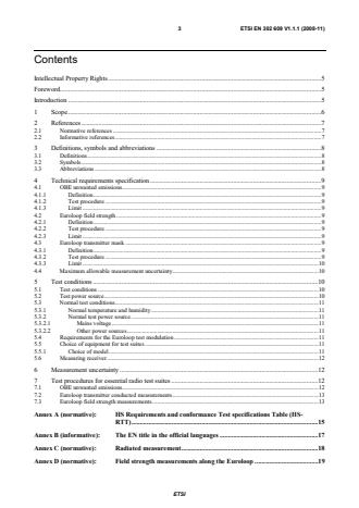

ETSI EN 302 609 V1.1.1 (2008-11) - Electromagnetic compatibility and Radio spectrum Matters (ERM); Short Range Devices (SRD); Radio equipment for Euroloop railway systems; Harmonized EN covering the essential requirements of article 3.2 of the R&TTE Directive

SIST EN 302 609 V1.1.1:2009 is the Slovene adoption of ETSI EN 302 609 V1.1.1, a Harmonized European Standard for Euroloop railway radio equipment. It specifies radio spectrum and electromagnetic compatibility requirements, test conditions, and measurement methods for the On-Board Equipment (OBE) and the Track-Side Equipment used in Euroloop transmission systems. The standard supports article 3.2 of the R&TTE Directive, so it is used to show that the equipment uses spectrum effectively and avoids harmful interference.
What does SIST EN 302 609 V1.1.1:2009 specify?
SIST EN 302 609 V1.1.1:2009 covers the technical requirements for radio transmitters and receivers used in the Euroloop transmission system in railway applications. It applies to two equipment units: the OBE, which receives the Euroloop signal, and the track-side Euroloop unit, which transmits the signal from the rail area.
The document is organized into clauses for scope, references, definitions, technical requirements, test conditions, measurement uncertainty, and test procedures. The annexes then connect the requirements to conformance testing and give supporting measurement methods.
| Annex | What it covers |
|---|---|
| Annex A | HS Requirements and conformance Test specifications Table linking requirements to test clauses |
| Annex C | Radiated measurement |
| Annex D | Field strength measurements along the Euroloop |
| Annex E | E-fields in the near field at low frequencies |
| Annex F | H-field measurements and limits at 3 m and 30 m |
What are the key requirements of SIST EN 302 609 V1.1.1:2009?
SIST EN 302 609 V1.1.1:2009 defines three essential radio test areas: unwanted emissions from the OBE, magnetic field strength from the Euroloop installation, and the Euroloop transmitter spectrum mask. In practice, these are the checks that show whether the equipment can operate in the railway environment without causing unacceptable interference.
OBE unwanted emissions
Clause 4.1 applies only to the OBE. The OBE is checked for unwanted emissions with radiated measurement below 30 MHz and conducted measurement from 30 MHz to 1 000 MHz.
For a manufacturer, this means the receiver unit must be verified not to radiate or conduct spurious energy above the stated limits. For a test lab, it means using the correct split between radiated and conducted methods and recording the results against the limit.
Euroloop field strength
Clause 4.2 applies only to the Euroloop transmitter. The transmitted magnetic field strength is measured radiated in the railway environment, with results assessed over the installed loop length.
This matters because the track-side unit is part of the railway infrastructure, not a bench-top transmitter. The test shows whether the installed system stays within the permitted field strength across the relevant section of track.
Euroloop transmitter mask
Clause 4.3 applies only to Euroloop transmitters and is checked by conducted measurement. The transmitter spectrum must follow the specified mask, which controls the allowed spectral shape and out-of-band behavior.
In practice, this is the lab check that the transmitter output is spectrally well behaved before installation. It helps confirm that the transmitter does not occupy or spill into frequencies outside its intended operation.
Test conditions and test setup
Clause 5 sets the test conditions, including normal temperature and humidity, the test power source, and the Euroloop test modulation. The applied DSSS code is the Euroloop test-code #15 from SUBSET-044, and the manufacturer must provide means to operate the transmitter during testing.
This matters because test results need to be repeatable and representative. It also tells the supplier what sample, power source, and operating mode the laboratory needs.
Equipment selection and uncertainty
Clause 5.5 says tests are carried out on production or equivalent preliminary models, and that optional features affecting RF parameters are tested in the worst-case configuration. Clause 6 requires measurement uncertainty to be reported and linked to the measured value used for compliance decisions.
For buyers and auditors, this is the evidence trail: which model was tested, how it was configured, and how uncertainty was handled. For labs, it means the report must show the uncertainty alongside the measurement result.
Measurement methods
Clause 7 gives the essential radio test suites for OBE unwanted emissions, Euroloop transmitter conducted measurements, and Euroloop field strength measurements. Annexes D, E, and F provide the calculation and conversion methods used when measurements are taken along the loop or at alternative distances.
What terms does SIST EN 302 609 V1.1.1:2009 define?
- dedicated antenna - A removable antenna supplied and tested with the radio equipment as an integral part of the system.
- euroloop - The wayside transmission unit that uses magnetic transmission technology to communicate with a passing train.
- magnetic transmission technology - A method that uses magnetic coupling in the air gap between transmitter and receiver.
- rf carrier - The fixed radio frequency before modulation.
- uplink - The transmission link from the Euroloop to the OBE.
- BPSK - Binary Phase Shift Keying, the modulation used for the Euroloop transmit signal.
- DSSS - Direct Sequence Spread Spectrum, the spread-spectrum method used in the Euroloop transmitter.
- OBE - On-Board Equipment, the train-mounted unit that receives the Euroloop signal.
Who uses SIST EN 302 609 V1.1.1:2009?
This standard is used by manufacturers of Euroloop OBE and track-side equipment, railway signalling suppliers, and test laboratories. It is also relevant to conformity assessment bodies, system integrators, and railway buyers who need a clear test basis for RF performance and interference control.
In practice, they use it to design the equipment, select a test configuration, run emissions and field-strength tests, and prepare technical documentation and test reports. For procurement, it helps define what evidence a supplier should provide for Euroloop radio equipment intended for railway use.
Which standards are used with SIST EN 302 609 V1.1.1:2009?
- ETSI TR 100 028 - Used for calculating measurement uncertainty for the test methods in this standard.
- ERTMS/ETCS - CLASS 1, SUBSET-044 FFFIS for Euroloop - Provides the Euroloop test-code and operating specification used during testing.
- ETSI TR 102 273 - Gives additional information on radiated methods of measurement and uncertainty.
- ETSI EN 302 608 - The related harmonized EN for Eurobalise railway systems, referenced for the Eurobalise OBE transmitter mask.
What does the SIST EN 302 609 V1.1.1:2009 document contain?
The document contains the testable RF requirements, the test conditions, the uncertainty rules, and the detailed measurement procedures used for Euroloop equipment. Annex A ties each requirement to its test clause for conformance work, while clause 7 gives the step-by-step test suites.
It also includes supporting methods for radiated measurement, field-strength evaluation along the loop, near-field conversion, and alternative measurement-distance conversion. Annex D provides the processing method for combining field components and extracting a representative loop envelope, and Annex F gives the distance conversion approach for 3 m and 30 m cases.
The document therefore serves as a practical conformance reference for design verification, laboratory testing, and technical file preparation for railway Euroloop radio equipment.
Buy Documents
ETSI EN 302 609 V1.1.1 (2007-12) - Electromagnetic compatibility and Radio spectrum Matters (ERM); Short Range Devices (SRD); Radio equipment for Euroloop railway systems; Harmonized EN covering the essential requirements of article 3.2 of the R&TTE Directive
ETSI EN 302 609 V1.1.1 (2008-08) - Electromagnetic compatibility and Radio spectrum Matters (ERM); Short Range Devices (SRD); Radio equipment for Euroloop railway systems; Harmonized EN covering the essential requirements of article 3.2 of the R&TTE Directive
ETSI EN 302 609 V1.1.1 (2008-11) - Electromagnetic compatibility and Radio spectrum Matters (ERM); Short Range Devices (SRD); Radio equipment for Euroloop railway systems; Harmonized EN covering the essential requirements of article 3.2 of the R&TTE Directive
Get Certified
Connect with accredited certification bodies for this standard

IRIS Certification (UNIFE)
International Railway Industry Standard certification.

TÜV SÜD Rail GmbH
TÜV SÜD railway certification services.

ANCE
Mexican certification and testing association.
Sponsored listings
Frequently Asked Questions
SIST EN 302 609 V1.1.1:2009 is a standard published by the Slovenian Institute for Standardization (SIST). Its full title is "Electromagnetic compatibility and Radio spectrum Matters (ERM) - Short Range Devices (SRD) - Radio equipment for Euroloop railway systems - Harmonized EN covering the essential requirements of article 3.2 of the R&TTE Directive". This standard covers: The present document covers the technical requirements for radio transmitters and receivers used in the Euroloop transmission system. The system is only used in railway systems. It applies to the following two equipment units as is shown in figure 1: The On-Board Equipment (OBE) receiving the Euroloop signal and the OBE comprises a receiver fitted with a dedicated antenna. The Track-Side Equipment (Euroloop) transmitting the Euroloop signal that is always installed in an inner or outer foot of a rail. The Euroloop comprises DSSS-BPSK-modulated transmitter fitted with a dedicated antenna. It is always switched on but is only transmitting in the presence of a train. The present document is intended to cover the provisions of Directive 1999/5/EC [i.6] (R&TTE Directive) article 3.2, which states that "… radio equipment shall be so constructed that it effectively uses the spectrum allocated to terrestrial/space radio communications and orbital resources so as to avoid harmful interference".
The present document covers the technical requirements for radio transmitters and receivers used in the Euroloop transmission system. The system is only used in railway systems. It applies to the following two equipment units as is shown in figure 1: The On-Board Equipment (OBE) receiving the Euroloop signal and the OBE comprises a receiver fitted with a dedicated antenna. The Track-Side Equipment (Euroloop) transmitting the Euroloop signal that is always installed in an inner or outer foot of a rail. The Euroloop comprises DSSS-BPSK-modulated transmitter fitted with a dedicated antenna. It is always switched on but is only transmitting in the presence of a train. The present document is intended to cover the provisions of Directive 1999/5/EC [i.6] (R&TTE Directive) article 3.2, which states that "… radio equipment shall be so constructed that it effectively uses the spectrum allocated to terrestrial/space radio communications and orbital resources so as to avoid harmful interference".
SIST EN 302 609 V1.1.1:2009 is classified under the following ICS (International Classification for Standards) categories: 33.060.20 - Receiving and transmitting equipment; 33.100.01 - Electromagnetic compatibility in general; 45.020 - Railway engineering in general. The ICS classification helps identify the subject area and facilitates finding related standards.
SIST EN 302 609 V1.1.1:2009 is associated with the following European legislation: EU Directives/Regulations: 1999/5/EC, 2005-01-1864, 2010-01-4558, TRRTP124; Standardization Mandates: M/364. When a standard is cited in the Official Journal of the European Union, products manufactured in conformity with it benefit from a presumption of conformity with the essential requirements of the corresponding EU directive or regulation.
SIST EN 302 609 V1.1.1:2009 is available in PDF format for immediate download after purchase. The document can be added to your cart and obtained through the secure checkout process. Digital delivery ensures instant access to the complete standard document.
Standards Content (Sample)
Draft ETSI EN 302 609 V1.1.1 (2007-12)
Harmonized European Standard (Telecommunications series)
Electromagnetic compatibility
and Radio spectrum Matters (ERM);
Short Range Devices (SRD);
Radio equipment for Euroloop railway systems;
Harmonized EN covering the essential requirements
of article 3.2 of the R&TTE Directive
2 Draft ETSI EN 302 609 V1.1.1 (2007-12)
Reference
DEN/ERM-TG28-0419
Keywords
radio, testing, SRD
ETSI
650 Route des Lucioles
F-06921 Sophia Antipolis Cedex - FRANCE
Tel.: +33 4 92 94 42 00 Fax: +33 4 93 65 47 16
Siret N° 348 623 562 00017 - NAF 742 C
Association à but non lucratif enregistrée à la
Sous-Préfecture de Grasse (06) N° 7803/88
Important notice
Individual copies of the present document can be downloaded from:
http://www.etsi.org
The present document may be made available in more than one electronic version or in print. In any case of existing or
perceived difference in contents between such versions, the reference version is the Portable Document Format (PDF).
In case of dispute, the reference shall be the printing on ETSI printers of the PDF version kept on a specific network drive
within ETSI Secretariat.
Users of the present document should be aware that the document may be subject to revision or change of status.
Information on the current status of this and other ETSI documents is available at
http://portal.etsi.org/tb/status/status.asp
If you find errors in the present document, please send your comment to one of the following services:
http://portal.etsi.org/chaircor/ETSI_support.asp
Copyright Notification
No part may be reproduced except as authorized by written permission.
The copyright and the foregoing restriction extend to reproduction in all media.
© European Telecommunications Standards Institute 2007.
All rights reserved.
TM TM TM TM
DECT , PLUGTESTS , UMTS , TIPHON , the TIPHON logo and the ETSI logo are Trade Marks of ETSI registered
for the benefit of its Members.
TM
3GPP is a Trade Mark of ETSI registered for the benefit of its Members and of the 3GPP Organizational Partners.
ETSI
3 Draft ETSI EN 302 609 V1.1.1 (2007-12)
Contents
Intellectual Property Rights.5
Foreword.5
Introduction .5
1 Scope.6
2 References.6
2.1 Normative references.7
2.2 Informative references.7
3 Definitions, symbols and abbreviations .7
3.1 Definitions.7
3.2 Symbols.8
3.3 Abbreviations.8
4 Technical requirements specification.8
4.1 OBE unwanted emissions.8
4.1.1 Definition.8
4.1.2 Test procedure.8
4.1.3 Limit.8
4.2 Euroloop field strength.8
4.2.1 Definition.8
4.2.2 Test procedure.9
4.2.3 Limit.9
4.3 Euroloop transmitter mask.9
4.3.1 Definition.9
4.3.2 Test procedure.9
4.3.3 Limit.9
4.4 Maximum allowable measurement uncertainty.9
5 Test conditions .10
5.1 Test conditions.10
5.2 Test power source.10
5.3 Normal test conditions.10
5.3.1 Normal temperature and humidity.10
5.3.2 Normal test power source .10
5.3.2.1 Mains voltage.10
5.3.2.2 Other power sources.10
5.4 Requirements for the Euroloop test modulation.11
5.5 Choice of equipment for test suites .11
5.5.1 Choice of model.11
5.6 Measuring receiver.11
6 Measurement uncertainty .11
7 Test procedures for essential radio test suites .12
7.1 OBE unwanted emissions.12
7.2 Euroloop transmitter conducted measurements.13
7.3 Euroloop field strength measurements .13
Annex A (normative): HS Requirements and conformance Test specifications Table (HS-
RTT).14
Annex B (informative): The EN title in the official languages .16
Annex C (normative): Radiated measurement.17
Annex D (normative): Field strength measurements along the Euroloop .18
ETSI
4 Draft ETSI EN 302 609 V1.1.1 (2007-12)
Annex E (informative): E-fields in the near field at low frequencies.19
Annex F (normative): H-field measurements and limits at 3 m and 30 m .21
F.1 Limits for measurements at 30 m distance.21
F.2 Limits for measurements at 3 m distance.22
Annex G (informative): Bibliography.23
History .24
ETSI
5 Draft ETSI EN 302 609 V1.1.1 (2007-12)
Intellectual Property Rights
IPRs essential or potentially essential to the present document may have been declared to ETSI. The information
pertaining to these essential IPRs, if any, is publicly available for ETSI members and non-members, and can be found
in ETSI SR 000 314: "Intellectual Property Rights (IPRs); Essential, or potentially Essential, IPRs notified to ETSI in
respect of ETSI standards", which is available from the ETSI Secretariat. Latest updates are available on the ETSI Web
server (http://webapp.etsi.org/IPR/home.asp).
Pursuant to the ETSI IPR Policy, no investigation, including IPR searches, has been carried out by ETSI. No guarantee
can be given as to the existence of other IPRs not referenced in ETSI SR 000 314 (or the updates on the ETSI Web
server) which are, or may be, or may become, essential to the present document.
Foreword
This Harmonized European Standard (Telecommunications series) has been produced by ETSI Technical Committee
Electromagnetic compatibility and Radio spectrum Matters (ERM), and is now submitted for the Public Enquiry phase
of the ETSI standards Two-step Approval Procedure.
The present document has been produced by ETSI in response to a mandate from the European Commission issued
under Council Directive 98/34/EC (as amended) laying down a procedure for the provision of information in the field of
technical standards and regulations.
The present document is intended to become a Harmonized Standard, the reference of which will be published in the
Official Journal of the European Communities referencing the Directive 1999/5/EC of the European Parliament and of
the Council of 9 March 1999 on radio equipment and telecommunications terminal equipment and the mutual
recognition of their conformity ("the R&TTE Directive ").
Technical specifications relevant to Directive 1999/5/EC are given in annex A.
The Euroloop transmission system operates in accordance with ERC Recommendation 70-03, annex 4.
These specifications are complementary with the system and interoperability requirements for these devices established
under Commission Decision 2004/447/EC.
Proposed national transposition dates
Date of latest announcement of this EN (doa): 3 months after ETSI publication
Date of latest publication of new National Standard
or endorsement of this EN (dop/e): 6 months after doa
Date of withdrawal of any conflicting National Standard (dow): 18 months after doa
Introduction
The present document is part of a set of standards developed by ETSI and is designed to fit in a modular structure to
cover all radio and telecommunications terminal equipment within the scope of the R&TTE Directive. The modular
structure is shown in EG 201 399 [4].
The Euroloop communication system is defined by the specifications of the UNISIG consortia [5].
ETSI
6 Draft ETSI EN 302 609 V1.1.1 (2007-12)
1 Scope
The present document covers the technical requirements for radio transmitters and receivers used in the Euroloop
transmission system. The system is only used in railway systems.
It applies to the following two equipment units:
• The OnBoard Equipment (OBE) receiving the Euroloop signal and the OBE comprises a receiver fitted with a
dedicated antenna.
• The TrackSide Equipment (Euroloop) transmitting the Euroloop signal that is always installed in an inner or
outer foot of a rail.
Interlocking
Train Control
System
Line side Electronic Unit
wake-up
Transmitter
Antenna
Receiver
Euroloop cable
Figure 1: Euroloop situation on railway track
The Euroloop comprises DSSS-BPSK-modulated transmitter fitted with a dedicated antenna. It is always switched on
but is only transmitting in the presence of a train.
These radio equipment types are capable of operating at the following frequencies as given below in table 1.
Table 1: Radiocommunications service frequency bands
Radiocommunications service frequency bands
OBE receive centre frequency 13,547 MHz
Euroloop receiver centre frequency 27,095 MHz
Euroloop transmit centre frequency 13,547 MHz
Euroloop transmit modulation BPSK, DSSS chip rate 4,516 MHz
The present document is intended to cover the provisions of Directive 1999/5/EC (R&TTE Directive) article 3.2, which
states that "… radio equipment shall be so constructed that it effectively uses the spectrum allocated to terrestrial/space
radio communications and orbital resources so as to avoid harmful interference".
NOTE: A list of such ENs is included on the web site http://www.newapproach.org.
2 References
References are either specific (identified by date of publication and/or edition number or version number) or
non-specific.
• For a specific reference, subsequent revisions do not apply.
• Non-specific reference may be made only to a complete document or a part thereof and only in the following
cases:
- if it is accepted that it will be possible to use all future changes of the referenced document for the purposes
of the referring document;
- for informative references.
ETSI
7 Draft ETSI EN 302 609 V1.1.1 (2007-12)
Referenced documents which are not found to be publicly available in the expected location might be found at
http://docbox.etsi.org/Reference.
For online referenced documents, information sufficient to identify and locate the source shall be provided. Preferably,
the primary source of the referenced document should be cited, in order to ensure traceability. Furthermore, the
reference should, as far as possible, remain valid for the expected life of the document. The reference shall include the
method of access to the referenced document and the full network address, with the same punctuation and use of upper
case and lower case letters.
NOTE: While any hyperlinks included in this clause were valid at the time of publication ETSI cannot guarantee
their long term validity.
2.1 Normative references
The following referenced documents are indispensable for the application of the present document. For dated
references, only the edition cited applies. For non-specific references, the latest edition of the referenced document
(including any amendments) applies.
[1] ETSI TR 100 028 (2001-12) (all parts): "Electromagnetic compatibility and Radio spectrum
Matters (ERM); Uncertainties in the measurement of mobile radio equipment characteristics".
[2] ERTMS/ETCS - CLASS 1, SUBSET-044 FFFIS for Euroloop.
2.2 Informative references
[3] ETSI TR 102 273 (2001-12) (all parts): "Electromagnetic compatibility and Radio spectrum
Matters (ERM): Improvement of radiated methods of measurement (using test sites) and
evaluation of the corresponding measurement uncertainties".
[4] ETSI EG 201 399 (V2.1.1): "Electromagnetic compatibility and Radio spectrum Matters (ERM);
A guide to the production of candidate Harmonized Standards for application under the R&TTE
Directive".
[5] The UNISIG Consortium was composed of the following European Companies working in the
Railway Signalling area: Alstom, Ansaldo Signal, Bombardier, Invesys Rail, Siemens, and Thales.
3 Definitions, symbols and abbreviations
3.1 Definitions
For the purposes of the present document, the following terms and definitions apply:
dedicated antenna: removable antenna supplied and tested with the radio equipment, designed as an indispensable part
of the equipment
euroloop: wayside transmission unit that uses the magnetic transmission technology
NOTE: Its main function is to transmit signals through the air gap. The Euroloop is a single device mounted on
the track, which communicates with a train passing over it.
magnetic transmission technology: method that uses magnetic coupling in the air gap between a transmitter and a
receiver
NOTE: In the Euroloop transmission system context, it considers systems using the 13,547 MHz for Uplink
(track to train) transmission.
rf carrier: a fixed radio frequency prior to modulation
uplink: transmission link from the Euroloop to the OBE
ETSI
8 Draft ETSI EN 302 609 V1.1.1 (2007-12)
3.2 Symbols
For the purposes of the present document, the following symbols apply:
f Frequency
f Highest frequency of the power envelope
H
f Lowest frequency of the power envelope
L
Ω ohm
R Distance
λ wavelength
3.3 Abbreviations
For the purposes of the present document, the following abbreviations apply:
BPSK Binary Phase Shift Keying
dB Decibel
DSSS Direct Sequence Spread Spectrum
OBE On-Board Equipment
R&TTE Radio and Telecommunications Terminal Equipment
RBW Resolution BandWidth
RF Radio Frequency
RMS Root mean square
SRD Short Range Device
4 Technical requirements specification
4.1 OBE unwanted emissions
4.1.1 Definition
This test only applies to the OBE.
NOTE: Eurobalise-OBU tele-powering is used for wake-up the Euroloop.
4.1.2 Test procedure
This test is performed using a radiated measurement for frequencies below 30 MHz and a conducted measurement for
frequencies from 3 MHz to 1 000 MHz (see clause 7.1 OBE unwanted emissions ).
4.1.3 Limit
The spurious components between 9 kHz and 10 MHz shall not exceed a generated H-field at a distance of 10 m of
5,5 dBµA/m at 9 kHz descending 3 dB/oct. and -22 dBµA/m between 10 MHz and 30 MHz measured in 10 kHz
bandwidth.
The spurious components above 30 MHz shall not exceed the conducted power of 2 nW into 50 Ω resistive load.
4.2 Euroloop field strength
4.2.1 Definition
This test only applies to Euroloop transmitter.
ETSI
9 Draft ETSI EN 302 609 V1.1.1 (2007-12)
4.2.2 Test procedure
This test is performed using a radiated measurement (see clause 7.3 Euroloop field strength measurements).
4.2.3 Limit
The transmitted magnetic field strength shall not exceed -7 dBµA/m at 10 m distance within the frequency range of
11,1 MHz to 16,0 MHz measured in a bandwidth of 10 kHz spatially averaged over any 200 m length of the loop.
4.3 Euroloop transmitter mask
4.3.1 Definition
This test only applies to Euroloop transmitters.
4.3.2 Test procedure
This test is performed using conducted measurement (see clause 7.2 Euroloop transmitter conducted measurements).
4.3.3 Limit
The measured spectrum (field strength) shall not exceed the relative frequency mask values of figure 2.
11.1MHz 16.0MHz
0dBc 0dBc
7.3MHz
-23dBc 23MHz
-23dBc
30MHz
-35dBc 1000MHz
1.0MHz -40dBc
-37dBc
.
1 10 100 1 10
Frequency, MHz
Figure 2: Euroloop transmitter spectrum and spurious mask
The limit at 1 MHz shall also apply for frequencies below 1 MHz.
4.4 Maximum allowable measurement uncertainty
See clause 6 Measurement uncertainty, table 3.
ETSI
Relative Magnitude, dBc
10 Draft ETSI EN 302 609 V1.1.1 (2007-12)
5 Test conditions
5.1 Test conditions
Testing shall be made under normal test conditions.
NOTE: The Euroloop system components (OBE as well as the Euroloop) are built for interoperability and the
UNISIG specifications apply over the full operating temperature range (including the spectrum masks).
The test conditions and procedures shall be as specified in clauses 5.2 Test power source to 5.6 Measuring receiver.
5.2 Test power source
The OBE and Euroloop equipment shall be tested using the appropriate test power source.
The test power source used shall be stated in the test report.
During the tests, the power source of the equipment shall be replaced by an external test power source capable of
producing normal test voltages as specified in clauses 5.3.2. The internal impedance of the external test power source
shall be low enough for its effect on the test results to be negligible. For the purpose of the tests, the voltage of the
external test power source shall be measured at the input terminals of the equipment. For radiated measurements any
external power leads should be so arranged so as not to affect the measurements.
During tests the test power s
...
Final draft ETSI EN 302 609 V1.1.1 (2008-08)
Harmonized European Standard (Telecommunications series)
Electromagnetic compatibility
and Radio spectrum Matters (ERM);
Short Range Devices (SRD);
Radio equipment for Euroloop railway systems;
Harmonized EN covering the essential requirements
of article 3.2 of the R&TTE Directive
2 Final draft ETSI EN 302 609 V1.1.1 (2008-08)
Reference
DEN/ERM-TG28-0419
Keywords
radio, SRD, testing
ETSI
650 Route des Lucioles
F-06921 Sophia Antipolis Cedex - FRANCE
Tel.: +33 4 92 94 42 00 Fax: +33 4 93 65 47 16
Siret N° 348 623 562 00017 - NAF 742 C
Association à but non lucratif enregistrée à la
Sous-Préfecture de Grasse (06) N° 7803/88
Important notice
Individual copies of the present document can be downloaded from:
http://www.etsi.org
The present document may be made available in more than one electronic version or in print. In any case of existing or
perceived difference in contents between such versions, the reference version is the Portable Document Format (PDF).
In case of dispute, the reference shall be the printing on ETSI printers of the PDF version kept on a specific network drive
within ETSI Secretariat.
Users of the present document should be aware that the document may be subject to revision or change of status.
Information on the current status of this and other ETSI documents is available at
http://portal.etsi.org/tb/status/status.asp
If you find errors in the present document, please send your comment to one of the following services:
http://portal.etsi.org/chaircor/ETSI_support.asp
Copyright Notification
No part may be reproduced except as authorized by written permission.
The copyright and the foregoing restriction extend to reproduction in all media.
© European Telecommunications Standards Institute 2008.
All rights reserved.
TM TM TM TM
DECT , PLUGTESTS , UMTS , TIPHON , the TIPHON logo and the ETSI logo are Trade Marks of ETSI registered
for the benefit of its Members.
TM
3GPP is a Trade Mark of ETSI registered for the benefit of its Members and of the 3GPP Organizational Partners.
ETSI
3 Final draft ETSI EN 302 609 V1.1.1 (2008-08)
Contents
Intellectual Property Rights.5
Foreword.5
Introduction .5
1 Scope.6
2 References.7
2.1 Normative references.7
2.2 Informative references.7
3 Definitions, symbols and abbreviations .8
3.1 Definitions.8
3.2 Symbols.8
3.3 Abbreviations.8
4 Technical requirements specification.9
4.1 OBE unwanted emissions.9
4.1.1 Definition.9
4.1.2 Test procedure.9
4.1.3 Limit.9
4.2 Euroloop field strength.9
4.2.1 Definition.9
4.2.2 Test procedure.9
4.2.3 Limit.9
4.3 Euroloop transmitter mask.9
4.3.1 Definition.9
4.3.2 Test procedure.9
4.3.3 Limit.10
4.4 Maximum allowable measurement uncertainty.10
5 Test conditions .10
5.1 Test conditions.10
5.2 Test power source.10
5.3 Normal test conditions.11
5.3.1 Normal temperature and humidity.11
5.3.2 Normal test power source .11
5.3.2.1 Mains voltage.11
5.3.2.2 Other power sources.11
5.4 Requirements for the Euroloop test modulation.11
5.5 Choice of equipment for test suites .11
5.5.1 Choice of model.11
5.6 Measuring receiver.12
6 Measurement uncertainty .12
7 Test procedures for essential radio test suites .12
7.1 OBE unwanted emissions.12
7.2 Euroloop transmitter conducted measurements.13
7.3 Euroloop field strength measurements .13
Annex A (normative): HS Requirements and conformance Test specifications Table (HS-
RTT).15
Annex B (informative): The EN title in the official languages .17
Annex C (normative): Radiated measurement.18
Annex D (normative): Field strength measurements along the Euroloop .19
ETSI
4 Final draft ETSI EN 302 609 V1.1.1 (2008-08)
Annex E (informative): E-fields in the near field at low frequencies.20
Annex F (normative): H-field measurements and limits at 3 m and 30 m .22
F.1 Limits for measurements at 30 m distance.22
F.2 Limits for measurements at 3 m distance.23
Annex G (informative): Bibliography.24
History .25
ETSI
5 Final draft ETSI EN 302 609 V1.1.1 (2008-08)
Intellectual Property Rights
IPRs essential or potentially essential to the present document may have been declared to ETSI. The information
pertaining to these essential IPRs, if any, is publicly available for ETSI members and non-members, and can be found
in ETSI SR 000 314: "Intellectual Property Rights (IPRs); Essential, or potentially Essential, IPRs notified to ETSI in
respect of ETSI standards", which is available from the ETSI Secretariat. Latest updates are available on the ETSI Web
server (http://webapp.etsi.org/IPR/home.asp).
Pursuant to the ETSI IPR Policy, no investigation, including IPR searches, has been carried out by ETSI. No guarantee
can be given as to the existence of other IPRs not referenced in ETSI SR 000 314 (or the updates on the ETSI Web
server) which are, or may be, or may become, essential to the present document.
Foreword
This Harmonized European Standard (Telecommunications series) has been produced by ETSI Technical Committee
Electromagnetic compatibility and Radio spectrum Matters (ERM), and is now submitted for the Vote phase of the
ETSI standards Two-step Approval Procedure.
The present document has been produced by ETSI in response to a mandate from the European Commission issued
under Council Directive 98/34/EC [i.5] (as amended) laying down a procedure for the provision of information in the
field of technical standards and regulations.
The present document is intended to become a Harmonized Standard, the reference of which will be published in the
Official Journal of the European Communities referencing the Directive 1999/5/EC [i.6] of the European Parliament
and of the Council of 9 March 1999 on radio equipment and telecommunications terminal equipment and the mutual
recognition of their conformity ("the R&TTE Directive").
Technical specifications relevant to Directive 1999/5/EC [i.6] are given in annex A.
The Euroloop transmission system operates in accordance with ERC Recommendation 70-03, annex 4.
These specifications are complementary with the system and interoperability requirements for these devices established
under Commission Decision 2004/447/EC [i.7].
Proposed national transposition dates
Date of latest announcement of this EN (doa): 3 months after ETSI publication
Date of latest publication of new National Standard
or endorsement of this EN (dop/e): 6 months after doa
Date of withdrawal of any conflicting National Standard (dow): 18 months after doa
Introduction
The present document is part of a set of standards developed by ETSI and is designed to fit in a modular structure to
cover all radio and telecommunications terminal equipment within the scope of the R&TTE Directive. The modular
structure is shown in EG 201 399 [i.2].
The Euroloop communication system is defined by the specifications of the UNISIG consortia [i.3].
ETSI
6 Final draft ETSI EN 302 609 V1.1.1 (2008-08)
1 Scope
The present document covers the technical requirements for radio transmitters and receivers used in the Euroloop
transmission system. The system is only used in railway systems.
It applies to the following two equipment units as is shown in figure 6:
• The On-Board Equipment (OBE) receiving the Euroloop signal and the OBE comprises a receiver fitted with a
dedicated antenna.
• The Track-Side Equipment (Euroloop) transmitting the Euroloop signal that is always installed in an inner or
outer foot of a rail.
Interlocking
Train Control
System
Line side Electronic Unit
wake-up
Transmitter
Antenna
Receiver
Euroloop cable
Figure 1: Euroloop situation on railway track
The Euroloop comprises DSSS-BPSK-modulated transmitter fitted with a dedicated antenna. It is always switched on
but is only transmitting in the presence of a train.
These radio equipment types are capable of operating at the following frequencies as given below in table 1.
Table 1: Radiocommunications service frequency bands
Radiocommunications service frequency bands
OBE receive centre frequency 13,547 MHz
Euroloop receiver centre frequency 27,095 MHz
Euroloop transmit centre frequency 13,547 MHz
Euroloop transmit modulation BPSK, DSSS chip rate 4,516 MHz
The present document is intended to cover the provisions of Directive 1999/5/EC [i.6] (R&TTE Directive) article 3.2,
which states that "… radio equipment shall be so constructed that it effectively uses the spectrum allocated to
terrestrial/space radio communications and orbital resources so as to avoid harmful interference".
NOTE: A list of such ENs is included on the web site http://www.newapproach.org.
ETSI
7 Final draft ETSI EN 302 609 V1.1.1 (2008-08)
2 References
References are either specific (identified by date of publication and/or edition number or version number) or
non-specific.
• For a specific reference, subsequent revisions do not apply.
• Non-specific reference may be made only to a complete document or a part thereof and only in the following
cases:
- if it is accepted that it will be possible to use all future changes of the referenced document for the
purposes of the referring document;
- for informative references.
Referenced documents which are not found to be publicly available in the expected location might be found at
http://docbox.etsi.org/Reference.
For online referenced documents, information sufficient to identify and locate the source shall be provided. Preferably,
the primary source of the referenced document should be cited, in order to ensure traceability. Furthermore, the
reference should, as far as possible, remain valid for the expected life of the document. The reference shall include the
method of access to the referenced document and the full network address, with the same punctuation and use of upper
case and lower case letters.
NOTE: While any hyperlinks included in this clause were valid at the time of publication ETSI cannot guarantee
their long term validity.
2.1 Normative references
The following referenced documents are indispensable for the application of the present document. For dated
references, only the edition cited applies. For non-specific references, the latest edition of the referenced document
(including any amendments) applies.
[1] ETSI TR 100 028 (2001) (all parts): "Electromagnetic compatibility and Radio spectrum Matters
(ERM); Uncertainties in the measurement of mobile radio equipment characteristics".
[2] ERTMS/ETCS - CLASS 1, SUBSET-044 FFFIS for Euroloop.
2.2 Informative references
The following referenced documents are not essential to the use of the ETSI deliverable but they assist the user with
regard to a particular subject area. For non-specific references, the latest version of the referenced document (including
any amendments) applies.
[i.1] ETSI TR 102 273 (2001) (all parts): "Electromagnetic compatibility and Radio spectrum Matters
(ERM); Improvement on Radiated Methods of Measurement (using test site) and evaluation of the
corresponding measurement uncertainties".
[i.2] ETSI EG 201 399 (V2.1.1): "Electromagnetic compatibility and Radio spectrum Matters (ERM);
A guide to the production of candidate Harmonized Standards for application under the R&TTE
Directive".
[i.3] The UNISIG Consortium was composed of the following European Companies working in the
Railway Signalling area: Alstom, Ansaldo Signal, Bombardier, Invesys Rail, Siemens, and Thales.
[i.4] ETSI EN 302 608 (V1.1.1): "Electromagnetic compatibility and Radio spectrum Matters (ERM);
Short Range Devices (SRD); Radio Equipment for Eurobalise railway systems; Harmonized EN
covering the essential requirements of article 3.2 of the R&TTE Directive".
[i.5] Directive 98/34/EC of the European Parliament and of the Council of 22 June 1998 laying down a
procedure for the provision of information in the field of technical standards and regulations.
ETSI
8 Final draft ETSI EN 302 609 V1.1.1 (2008-08)
[i.6] Directive 1999/5/EC of the European Parliament and of the Council of 9 March 1999 on radio
equipment and telecommunications terminal equipment and the mutual recognition of their
conformity (R&TTE Directive).
[i.7] Commission Decision 2004/447/EC of 29 April 2004 modifying annex A to Decision
2002/731/EC of 30 May 2002 and establishing the main characteristics of Class A system
(ERTMS) of the control-command and signalling subsystem of the trans-European conventional
rail system referred to in Directive 2001/16/EC of the European Parliament and of the Council.
3 Definitions, symbols and abbreviations
3.1 Definitions
For the purposes of the present document, the following terms and definitions apply:
dedicated antenna: removable antenna supplied and tested with the radio equipment, designed as an indispensable part
of the equipment
euroloop: wayside transmission unit that uses the magnetic transmission technology
NOTE: Its main function is to transmit signals through the air gap. The Euroloop is a single device mounted on
the track, which communicates with a train passing over it.
magnetic transmission technology: method that uses magnetic coupling in the air gap between a transmitter and a
receiver
NOTE: In the Euroloop transmission system context, it considers systems using the 13,547 MHz for Uplink
(track to train) transmission.
rf carrier: fixed radio frequency prior to modulation
uplink: transmission link from the Euroloop to the OBE
3.2 Symbols
For the purposes of the present document, the following symbols apply:
f Frequency
f Highest frequency of the power envelope
H
f Lowest frequency of the power envelope
L
Ω ohm
R Distance
λ wavelength
3.3 Abbreviations
For the purposes of the present document, the following abbreviations apply:
BPSK Binary Phase Shift Keying
dB deciBel
DSSS Direct Sequence Spread Spectrum
OBE On-Board Equipment
R&TTE Radio and Telecommunications Terminal Equipment
RF Radio Frequency
RMS Root Mean Square
SRD Short Range Device
VSWR Voltage Standing Wave Ratio
ETSI
9 Final draft ETSI EN 302 609 V1.1.1 (2008-08)
4 Technical requirements specification
4.1 OBE unwanted emissions
4.1.1 Definition
This test only applies to the OBE.
NOTE: Eurobalise-OBU tele-powering is used for wake-up of the Euroloop. The Eurobalise OBE transmitter
mask is defined in EN 302 608 [i.4].
4.1.2 Test procedure
This test is performed using a radiated measurement for frequencies below 30 MHz and a conducted measurement for
frequencies from 30 MHz to 1 000 MHz (see clause 7.1).
4.1.3 Limit
The spurious components between 9 kHz and 10 MHz shall not exceed a generated H-field at a distance of 10 m of
5,5 dBµA/m at 9 kHz descending 3 dB/oct. and -22 dBµA/m between 10 MHz and 30 MHz measured in 10 kHz
bandwidth.
The spurious components above 30 MHz shall not exceed the conducted power of 2 nW into 50 Ω resistive load.
4.2 Euroloop field strength
4.2.1 Definition
This test only applies to the Euroloop transmitter.
4.2.2 Test procedure
This test is performed using a radiated measurement (see clause 7.3).
4.2.3 Limit
The transmitted magnetic field strength shall not exceed -7 dBµA/m at 10 m distance within the frequency range of
11,1 MHz to 16,0 MHz measured in a bandwidth of 10 kHz spatially averaged over any 200 m length of the loop.
4.3 Euroloop transmitter mask
4.3.1 Definition
This test only applies to Euroloop transmitters.
4.3.2 Test procedure
This test is performed using conducted measurement (see clause 7.2).
ETSI
10 Final draft ETSI EN 302 609 V1.1.1 (2008-08)
4.3.3 Limit
The measured spectrum (field strength) shall not exceed the relative frequency mask values of figure 2.
11,1MHz 16,0MHz
0dBc 0dBc
7,3MHz
-23dBc 23MHz
-23dBc
30MHz
-35dBc 1000MHz
1,0MHz -40dBc
-37dBc
.
1 10 100 1 10
Frequency, MHz
Figure 2: Euroloop transmitter spectrum and spurious mask
The limit at 1 MHz shall also apply for frequencies below 1 MHz.
4.4 Maximum allowable measurement uncertainty
See clause 6, table 3.
5 Test conditions
5.1 Test conditions
Testing shall be made under normal test conditions.
NOTE: The Euroloop system components (OBE as well as the Euroloop) are built for interoperability and the
UNISIG specifications apply over the full oper
...
Harmonized European Standard (Telecommunications series)
Electromagnetic compatibility
and Radio spectrum Matters (ERM);
Short Range Devices (SRD);
Radio equipment for Euroloop railway systems;
Harmonized EN covering the essential requirements
of article 3.2 of the R&TTE Directive
2 ETSI EN 302 609 V1.1.1 (2008-11)
Reference
DEN/ERM-TG28-0419
Keywords
radio, SRD, testing
ETSI
650 Route des Lucioles
F-06921 Sophia Antipolis Cedex - FRANCE
Tel.: +33 4 92 94 42 00 Fax: +33 4 93 65 47 16
Siret N° 348 623 562 00017 - NAF 742 C
Association à but non lucratif enregistrée à la
Sous-Préfecture de Grasse (06) N° 7803/88
Important notice
Individual copies of the present document can be downloaded from:
http://www.etsi.org
The present document may be made available in more than one electronic version or in print. In any case of existing or
perceived difference in contents between such versions, the reference version is the Portable Document Format (PDF).
In case of dispute, the reference shall be the printing on ETSI printers of the PDF version kept on a specific network drive
within ETSI Secretariat.
Users of the present document should be aware that the document may be subject to revision or change of status.
Information on the current status of this and other ETSI documents is available at
http://portal.etsi.org/tb/status/status.asp
If you find errors in the present document, please send your comment to one of the following services:
http://portal.etsi.org/chaircor/ETSI_support.asp
Copyright Notification
No part may be reproduced except as authorized by written permission.
The copyright and the foregoing restriction extend to reproduction in all media.
© European Telecommunications Standards Institute 2008.
All rights reserved.
TM TM TM TM
DECT , PLUGTESTS , UMTS , TIPHON , the TIPHON logo and the ETSI logo are Trade Marks of ETSI registered
for the benefit of its Members.
TM
3GPP is a Trade Mark of ETSI registered for the benefit of its Members and of the 3GPP Organizational Partners.
ETSI
3 ETSI EN 302 609 V1.1.1 (2008-11)
Contents
Intellectual Property Rights . 5
Foreword . 5
Introduction . 5
1 Scope . 6
2 References . 7
2.1 Normative references . 7
2.2 Informative references . 7
3 Definitions, symbols and abbreviations . 8
3.1 Definitions . 8
3.2 Symbols . 8
3.3 Abbreviations . 8
4 Technical requirements specification . 9
4.1 OBE unwanted emissions . 9
4.1.1 Definition . 9
4.1.2 Test procedure . 9
4.1.3 Limit . 9
4.2 Euroloop field strength . 9
4.2.1 Definition . 9
4.2.2 Test procedure . 9
4.2.3 Limit . 9
4.3 Euroloop transmitter mask . 9
4.3.1 Definition . 9
4.3.2 Test procedure . 9
4.3.3 Limit . 10
4.4 Maximum allowable measurement uncertainty . 10
5 Test conditions . 10
5.1 Test conditions . 10
5.2 Test power source . 10
5.3 Normal test conditions . 11
5.3.1 Normal temperature and humidity . 11
5.3.2 Normal test power source . 11
5.3.2.1 Mains voltage . 11
5.3.2.2 Other power sources . 11
5.4 Requirements for the Euroloop test modulation . 11
5.5 Choice of equipment for test suites . 11
5.5.1 Choice of model . 11
5.6 Measuring receiver . 12
6 Measurement uncertainty . 12
7 Test procedures for essential radio test suites . 12
7.1 OBE unwanted emissions . 12
7.2 Euroloop transmitter conducted measurements . 13
7.3 Euroloop field strength measurements . 13
Annex A (normative): HS Requirements and conformance Test specifications Table (HS-
RTT) . 15
Annex B (informative): The EN title in the official languages . 17
Annex C (normative): Radiated measurement . 18
Annex D (normative): Field strength measurements along the Euroloop . 19
ETSI
4 ETSI EN 302 609 V1.1.1 (2008-11)
Annex E (informative): E-fields in the near field at low frequencies . 20
Annex F (normative): H-field measurements and limits at 3 m and 30 m . 22
F.1 Limits for measurements at 30 m distance . 22
F.2 Limits for measurements at 3 m distance . 23
Annex G (informative): Bibliography . 24
History . 25
ETSI
5 ETSI EN 302 609 V1.1.1 (2008-11)
Intellectual Property Rights
IPRs essential or potentially essential to the present document may have been declared to ETSI. The information
pertaining to these essential IPRs, if any, is publicly available for ETSI members and non-members, and can be found
in ETSI SR 000 314: "Intellectual Property Rights (IPRs); Essential, or potentially Essential, IPRs notified to ETSI in
respect of ETSI standards", which is available from the ETSI Secretariat. Latest updates are available on the ETSI Web
server (http://webapp.etsi.org/IPR/home.asp).
Pursuant to the ETSI IPR Policy, no investigation, including IPR searches, has been carried out by ETSI. No guarantee
can be given as to the existence of other IPRs not referenced in ETSI SR 000 314 (or the updates on the ETSI Web
server) which are, or may be, or may become, essential to the present document.
Foreword
This Harmonized European Standard (Telecommunications series) has been produced by ETSI Technical Committee
Electromagnetic compatibility and Radio spectrum Matters (ERM).
The present document has been produced by ETSI in response to a mandate from the European Commission issued
under Council Directive 98/34/EC [i.5] (as amended) laying down a procedure for the provision of information in the
field of technical standards and regulations.
The present document is intended to become a Harmonized Standard, the reference of which will be published in the
Official Journal of the European Communities referencing the Directive 1999/5/EC [i.6] of the European Parliament
and of the Council of 9 March 1999 on radio equipment and telecommunications terminal equipment and the mutual
recognition of their conformity ("the R&TTE Directive").
Technical specifications relevant to Directive 1999/5/EC [i.6] are given in annex A.
The Euroloop transmission system operates in accordance with ERC Recommendation 70-03, annex 4.
These specifications are complementary with the system and interoperability requirements for these devices established
under Commission Decision 2004/447/EC [i.7].
National transposition dates
Date of adoption of this EN: 28 October 2008
Date of latest announcement of this EN (doa): 31 January 2009
Date of latest publication of new National Standard
or endorsement of this EN (dop/e): 31 July 2009
Date of withdrawal of any conflicting National Standard (dow): 31 July 2010
Introduction
The present document is part of a set of standards developed by ETSI and is designed to fit in a modular structure to
cover all radio and telecommunications terminal equipment within the scope of the R&TTE Directive. The modular
structure is shown in EG 201 399 [i.2].
The Euroloop communication system is defined by the specifications of the UNISIG consortia [i.3].
ETSI
6 ETSI EN 302 609 V1.1.1 (2008-11)
1 Scope
The present document covers the technical requirements for radio transmitters and receivers used in the Euroloop
transmission system. The system is only used in railway systems.
It applies to the following two equipment units as is shown in figure 1:
• The On-Board Equipment (OBE) receiving the Euroloop signal and the OBE comprises a receiver fitted with a
dedicated antenna.
• The Track-Side Equipment (Euroloop) transmitting the Euroloop signal that is always installed in an inner or
outer foot of a rail.
Interlocking
Train Control
System
Line side Electronic Unit
wake-up
Transmitter
Antenna
Receiver
Euroloop cable
Figure 1: Euroloop situation on railway track
The Euroloop comprises DSSS-BPSK-modulated transmitter fitted with a dedicated antenna. It is always switched on
but is only transmitting in the presence of a train.
These radio equipment types are capable of operating at the following frequencies as given below in table 1.
Table 1: Radiocommunications service frequency bands
Radiocommunications service frequency bands
OBE receive centre frequency 13,547 MHz
Euroloop receiver centre frequency 27,095 MHz
Euroloop transmit centre frequency 13,547 MHz
Euroloop transmit modulation BPSK, DSSS chip rate 4,516 MHz
The present document is intended to cover the provisions of Directive 1999/5/EC [i.6] (R&TTE Directive) article 3.2,
which states that "… radio equipment shall be so constructed that it effectively uses the spectrum allocated to
terrestrial/space radio communications and orbital resources so as to avoid harmful interference".
NOTE: A list of such ENs is included on the web site http://www.newapproach.org.
ETSI
7 ETSI EN 302 609 V1.1.1 (2008-11)
2 References
References are either specific (identified by date of publication and/or edition number or version number) or
non-specific.
• For a specific reference, subsequent revisions do not apply.
• Non-specific reference may be made only to a complete document or a part thereof and only in the following
cases:
- if it is accepted that it will be possible to use all future changes of the referenced document for the
purposes of the referring document;
- for informative references.
Referenced documents which are not found to be publicly available in the expected location might be found at
http://docbox.etsi.org/Reference.
For online referenced documents, information sufficient to identify and locate the source shall be provided. Preferably,
the primary source of the referenced document should be cited, in order to ensure traceability. Furthermore, the
reference should, as far as possible, remain valid for the expected life of the document. The reference shall include the
method of access to the referenced document and the full network address, with the same punctuation and use of upper
case and lower case letters.
NOTE: While any hyperlinks included in this clause were valid at the time of publication ETSI cannot guarantee
their long term validity.
2.1 Normative references
The following referenced documents are indispensable for the application of the present document. For dated
references, only the edition cited applies. For non-specific references, the latest edition of the referenced document
(including any amendments) applies.
[1] ETSI TR 100 028 (2001) (all parts): "Electromagnetic compatibility and Radio spectrum Matters
(ERM); Uncertainties in the measurement of mobile radio equipment characteristics".
[2] ERTMS/ETCS - CLASS 1, SUBSET-044 FFFIS for Euroloop.
2.2 Informative references
The following referenced documents are not essential to the use of the ETSI deliverable but they assist the user with
regard to a particular subject area. For non-specific references, the latest version of the referenced document (including
any amendments) applies.
[i.1] ETSI TR 102 273 (2001) (all parts): "Electromagnetic compatibility and Radio spectrum Matters
(ERM); Improvement on Radiated Methods of Measurement (using test site) and evaluation of the
corresponding measurement uncertainties".
[i.2] ETSI EG 201 399 (V2.1.1): "Electromagnetic compatibility and Radio spectrum Matters (ERM);
A guide to the production of candidate Harmonized Standards for application under the R&TTE
Directive".
[i.3] The UNISIG Consortium was composed of the following European Companies working in the
Railway Signalling area: Alstom, Ansaldo Signal, Bombardier, Invesys Rail, Siemens, and Thales.
[i.4] ETSI EN 302 608 (V1.1.1): "Electromagnetic compatibility and Radio spectrum Matters (ERM);
Short Range Devices (SRD); Radio Equipment for Eurobalise railway systems; Harmonized EN
covering the essential requirements of article 3.2 of the R&TTE Directive".
[i.5] Directive 98/34/EC of the European Parliament and of the Council of 22 June 1998 laying down a
procedure for the provision of information in the field of technical standards and regulations.
ETSI
8 ETSI EN 302 609 V1.1.1 (2008-11)
[i.6] Directive 1999/5/EC of the European Parliament and of the Council of 9 March 1999 on radio
equipment and telecommunications terminal equipment and the mutual recognition of their
conformity (R&TTE Directive).
[i.7] Commission Decision 2004/447/EC of 29 April 2004 modifying annex A to Decision
2002/731/EC of 30 May 2002 and establishing the main characteristics of Class A system
(ERTMS) of the control-command and signalling subsystem of the trans-European conventional
rail system referred to in Directive 2001/16/EC of the European Parliament and of the Council.
3 Definitions, symbols and abbreviations
3.1 Definitions
For the purposes of the present document, the following terms and definitions apply:
dedicated antenna: removable antenna supplied and tested with the radio equipment, designed as an indispensable part
of the equipment
euroloop: wayside transmission unit that uses the magnetic transmission technology
NOTE: Its main function is to transmit signals through the air gap. The Euroloop is a single device mounted on
the track, which communicates with a train passing over it.
magnetic transmission technology: method that uses magnetic coupling in the air gap between a transmitter and a
receiver
NOTE: In the Euroloop transmission system context, it considers systems using the 13,547 MHz for Uplink
(track to train) transmission.
rf carrier: fixed radio frequency prior to modulation
uplink: transmission link from the Euroloop to the OBE
3.2 Symbols
For the purposes of the present document, the following symbols apply:
f Frequency
f Highest frequency of the power envelope
H
f Lowest frequency of the power envelope
L
Ω ohm
R Distance
λ wavelength
3.3 Abbreviations
For the purposes of the present document, the following abbreviations apply:
BPSK Binary Phase Shift Keying
dB deciBel
DSSS Direct Sequence Spread Spectrum
OBE On-Board Equipment
R&TTE Radio and Telecommunications Terminal Equipment
RF Radio Frequency
RMS Root Mean Square
SRD Short Range Device
VSWR Voltage Standing Wave Ratio
ETSI
9 ETSI EN 302 609 V1.1.1 (2008-11)
4 Technical requirements specification
4.1 OBE unwanted emissions
4.1.1 Definition
This test only applies to the OBE.
NOTE: Eurobalise-OBU tele-powering is used for wake-up of the Euroloop. The Eurobalise OBE transmitter
mask is defined in EN 302 608 [i.4].
4.1.2 Test procedure
This test is performed using a radiated measurement for frequencies below 30 MHz and a conducted measurement for
frequencies from 30 MHz to 1 000 MHz (see clause 7.1).
4.1.3 Limit
The spurious components between 9 kHz and 10 MHz shall not exceed a generated H-field at a distance of 10 m of
5,5 dBµA/m at 9 kHz descending 3 dB/oct. and -22 dBµA/m between 10 MHz and 30 MHz measured in 10 kHz
bandwidth.
The spurious components above 30 MHz shall not exceed the conducted power of 2 nW into 50 Ω resistive load.
4.2 Euroloop field strength
4.2.1 Definition
This test only applies to the Euroloop transmitter.
4.2.2 Test procedure
This test is performed using a radiated measurement (see clause 7.3).
4.2.3 Limit
The transmitted magnetic field strength shall not exceed -7 dBµA/m at 10 m distance within the frequency range of
11,1 MHz to 16,0 MHz measured in a bandwidth of 10 kHz spatially averaged over any 200 m length of the loop.
4.3 Euroloop transmitter mask
4.3.1 Definition
This test only applies to Euroloop transmitters.
4.3.2 Test procedure
This test is performed using conducted measurement (see clause 7.2).
ETSI
10 ETSI EN 302 609 V1.1.1 (2008-11)
4.3.3 Limit
The measured spectrum (field strength) shall not exceed the relative frequency mask values of figure 2.
11,1MHz 16,0MHz
0dBc 0dBc
7,3MHz
-23dBc 23MHz
-23dBc
30MHz
-35dBc 1000MHz
1,0MHz -40dBc
-37dBc
.
1 10 100 1 10
Frequency, MHz
Figure 2: Euroloop transmitter spectrum and spurious mask
The limit at 1 MHz shall also apply for frequencies below 1 MHz.
4.4 Maximum allowable measurement uncertainty
See clause 6, table 3.
5 Test conditions
5.1 Test conditions
Testing shall be made under normal test conditions.
NOTE: The Euroloop system components (OBE as well as the Euroloop) are built for interoperability and the
UNISIG specifications appl
...
2003-01.Slovenski inštitut za standardizacijo. Razmnoževanje celote ali delov tega standarda ni dovoljeno.Electromagnetic compatibility and Radio spectrum Matters (ERM) - Short Range Devices (SRD) - Radio equipment for Euroloop railway systems - Harmonized EN covering the essential requirements of article 3.2 of the R&TTE Directive45.020Železniška tehnika na splošnoRailway engineering in general33.100.01Elektromagnetna združljivost na splošnoElectromagnetic compatibility in general33.060.20Sprejemna in oddajna opremaReceiving and transmitting equipmentICS:Ta slovenski standard je istoveten z:EN 302 609 Version 1.1.1SIST EN 302 609 V1.1.1:2009en01-marec-2009SIST EN 302 609 V1.1.1:2009SLOVENSKI
STANDARD
ETSI ETSI EN 302 609 V1.1.1 (2008-11) 2
Reference DEN/ERM-TG28-0419 Keywords radio, SRD, testing ETSI 650 Route des Lucioles F-06921 Sophia Antipolis Cedex - FRANCE
Tel.: +33 4 92 94 42 00
Fax: +33 4 93 65 47 16
Siret N° 348 623 562 00017 - NAF 742 C Association à but non lucratif enregistrée à la Sous-Préfecture de Grasse (06) N° 7803/88
Important notice Individual copies of the present document can be downloaded from: http://www.etsi.org The present document may be made available in more than one electronic version or in print. In any case of existing or perceived difference in contents between such versions, the reference version is the Portable Document Format (PDF). In case of dispute, the reference shall be the printing on ETSI printers of the PDF version kept on a specific network drive within ETSI Secretariat. Users of the present document should be aware that the document may be subject to revision or change of status. Information on the current status of this and other ETSI documents is available at http://portal.etsi.org/tb/status/status.asp If you find errors in the present document, please send your comment to one of the following services: http://portal.etsi.org/chaircor/ETSI_support.asp Copyright Notification No part may be reproduced except as authorized by written permission. The copyright and the foregoing restriction extend to reproduction in all media.
© European Telecommunications Standards Institute 2008. All rights reserved.
DECTTM, PLUGTESTSTM, UMTSTM, TIPHONTM, the TIPHON logo and the ETSI logo are Trade Marks of ETSI registered for the benefit of its Members. 3GPPTM is a Trade Mark of ETSI registered for the benefit of its Members and of the 3GPP Organizational Partners. SIST EN 302 609 V1.1.1:2009
ETSI ETSI EN 302 609 V1.1.1 (2008-11) 3 Contents Intellectual Property Rights . 5 Foreword . 5 Introduction . 5 1 Scope . 6 2 References . 7 2.1 Normative references . 7 2.2 Informative references . 7 3 Definitions, symbols and abbreviations . 8 3.1 Definitions . 8 3.2 Symbols . 8 3.3 Abbreviations . 8 4 Technical requirements specification . 9 4.1 OBE unwanted emissions . 9 4.1.1 Definition . 9 4.1.2 Test procedure . 9 4.1.3 Limit . 9 4.2 Euroloop field strength . 9 4.2.1 Definition . 9 4.2.2 Test procedure . 9 4.2.3 Limit . 9 4.3 Euroloop transmitter mask . 9 4.3.1 Definition . 9 4.3.2 Test procedure . 9 4.3.3 Limit . 10 4.4 Maximum allowable measurement uncertainty . 10 5 Test conditions . 10 5.1 Test conditions . 10 5.2 Test power source . 10 5.3 Normal test conditions . 11 5.3.1 Normal temperature and humidity . 11 5.3.2 Normal test power source . 11 5.3.2.1 Mains voltage . 11 5.3.2.2 Other power sources . 11 5.4 Requirements for the Euroloop test modulation . 11 5.5 Choice of equipment for test suites . 11 5.5.1 Choice of model . 11 5.6 Measuring receiver . 12 6 Measurement uncertainty . 12 7 Test procedures for essential radio test suites . 12 7.1 OBE unwanted emissions . 12 7.2 Euroloop transmitter conducted measurements . 13 7.3 Euroloop field strength measurements . 13 Annex A (normative): HS Requirements and conformance Test specifications Table (HS-RTT) . 15 Annex B (informative): The EN title in the official languages . 17 Annex C (normative): Radiated measurement . 18 Annex D (normative): Field strength measurements along the Euroloop . 19 SIST EN 302 609 V1.1.1:2009
ETSI ETSI EN 302 609 V1.1.1 (2008-11) 4 Annex E (informative): E-fields in the near field at low frequencies . 20 Annex F (normative): H-field measurements and limits at 3 m and 30 m . 22 F.1 Limits for measurements at 30 m distance . 22 F.2 Limits for measurements at 3 m distance . 23 Annex G (informative): Bibliography . 24 History . 25
ETSI ETSI EN 302 609 V1.1.1 (2008-11) 5 Intellectual Property Rights IPRs essential or potentially essential to the present document may have been declared to ETSI. The information pertaining to these essential IPRs, if any, is publicly available for ETSI members and non-members, and can be found in ETSI SR 000 314: "Intellectual Property Rights (IPRs); Essential, or potentially Essential, IPRs notified to ETSI in respect of ETSI standards", which is available from the ETSI Secretariat. Latest updates are available on the ETSI Web server (http://webapp.etsi.org/IPR/home.asp). Pursuant to the ETSI IPR Policy, no investigation, including IPR searches, has been carried out by ETSI. No guarantee can be given as to the existence of other IPRs not referenced in ETSI SR 000 314 (or the updates on the ETSI Web server) which are, or may be, or may become, essential to the present document. Foreword This Harmonized European Standard (Telecommunications series) has been produced by ETSI Technical Committee Electromagnetic compatibility and Radio spectrum Matters (ERM). The present document has been produced by ETSI in response to a mandate from the European Commission issued under Council Directive 98/34/EC [i.5] (as amended) laying down a procedure for the provision of information in the field of technical standards and regulations. The present document is intended to become a Harmonized Standard, the reference of which will be published in the Official Journal of the European Communities referencing the Directive 1999/5/EC [i.6] of the European Parliament and of the Council of 9 March 1999 on radio equipment and telecommunications terminal equipment and the mutual recognition of their conformity ("the R&TTE Directive"). Technical specifications relevant to Directive 1999/5/EC [i.6] are given in annex A. The Euroloop transmission system operates in accordance with ERC Recommendation 70-03, annex 4. These specifications are complementary with the system and interoperability requirements for these devices established under Commission Decision 2004/447/EC [i.7].
National transposition dates Date of adoption of this EN: 28 October 2008 Date of latest announcement of this EN (doa): 31 January 2009 Date of latest publication of new National Standard or endorsement of this EN (dop/e):
31 July 2009 Date of withdrawal of any conflicting National Standard (dow): 31 July 2010
Introduction The present document is part of a set of standards developed by ETSI and is designed to fit in a modular structure to cover all radio and telecommunications terminal equipment within the scope of the R&TTE Directive. The modular structure is shown in EG 201 399 [i.2]. The Euroloop communication system is defined by the specifications of the UNISIG consortia [i.3]. SIST EN 302 609 V1.1.1:2009
ETSI ETSI EN 302 609 V1.1.1 (2008-11) 6 1 Scope The present document covers the technical requirements for radio transmitters and receivers used in the Euroloop transmission system. The system is only used in railway systems. It applies to the following two equipment units as is shown in figure 1: • The On-Board Equipment (OBE) receiving the Euroloop signal and the OBE comprises a receiver fitted with a dedicated antenna. • The Track-Side Equipment (Euroloop) transmitting the Euroloop signal that is always installed in an inner or outer foot of a rail. AntennaTrain Control SystemLine side Electronic UnitInterlockingEuroloop cablewake-up Receiver Transmitter Figure 1: Euroloop situation on railway track The Euroloop comprises DSSS-BPSK-modulated transmitter fitted with a dedicated antenna. It is always switched on but is only transmitting in the presence of a train. These radio equipment types are capable of operating at the following frequencies as given below in table 1. Table 1: Radiocommunications service frequency bands
Radiocommunications service frequency bands OBE receive centre frequency 13,547 MHz Euroloop receiver centre frequency 27,095 MHz Euroloop transmit centre frequency 13,547 MHz Euroloop transmit modulation BPSK, DSSS chip rate 4,516 MHz
The present document is intended to cover the provisions of Directive 1999/5/EC [i.6] (R&TTE Directive) article 3.2, which states that "… radio equipment shall be so constructed that it effectively uses the spectrum allocated to terrestrial/space radio communications and orbital resources so as to avoid harmful interference". NOTE: A list of such ENs is included on the web site http://www.newapproach.org. SIST EN 302 609 V1.1.1:2009
ETSI ETSI EN 302 609 V1.1.1 (2008-11) 7 2 References References are either specific (identified by date of publication and/or edition number or version number) or non-specific. • For a specific reference, subsequent revisions do not apply. • Non-specific reference may be made only to a complete document or a part thereof and only in the following cases: - if it is accepted that it will be possible to use all future changes of the referenced document for the purposes of the referring document;
- for informative references. Referenced documents which are not found to be publicly available in the expected location might be found at http://docbox.etsi.org/Reference. For online referenced documents, information sufficient to identify and locate the source shall be provided. Preferably, the primary source of the referenced document should be cited, in order to ensure traceability. Furthermore, the reference should, as far as possible, remain valid for the expected life of the document. The reference shall include the method of access to the referenced document and the full network address, with the same punctuation and use of upper case and lower case letters. NOTE: While any hyperlinks included in this clause were valid at the time of publication ETSI cannot guarantee their long term validity. 2.1 Normative references The following referenced documents are indispensable for the application of the present document. For dated references, only the edition cited applies. For non-specific references, the latest edition of the referenced document (including any amendments) applies. [1] ETSI TR 100 028 (2001) (all parts): "Electromagnetic compatibility and Radio spectrum Matters (ERM); Uncertainties in the measurement of mobile radio equipment characteristics". [2] ERTMS/ETCS - CLASS 1, SUBSET-044 FFFIS for Euroloop. 2.2 Informative references The following referenced documents are not essential to the use of the ETSI deliverable but they assist the user with regard to a particular subject area. For non-specific references, the latest version of the referenced document (including any amendments) applies. [i.1] ETSI TR 102 273 (2001) (all parts): "Electromagnetic compatibility and Radio spectrum Matters (ERM); Improvement on Radiated Methods of Measurement (using test site) and evaluation of the corresponding measurement uncertainties". [i.2] ETSI EG 201 399 (V2.1.1): "Electromagnetic compatibility and Radio spectrum Matters (ERM); A guide to the production of candidate Harmonized Standards for application under the R&TTE Directive". [i.3] The UNISIG Consortium was composed of the following European Companies working in the Railway Signalling area: Alstom, Ansaldo Signal, Bombardier, Invesys Rail, Siemens, and Thales. [i.4] ETSI EN 302 608 (V1.1.1): "Electromagnetic compatibility and Radio spectrum Matters (ERM); Short Range Devices (SRD); Radio Equipment for Eurobalise railway systems; Harmonized EN covering the essential requirements of article 3.2 of the R&TTE Directive". [i.5] Directive 98/34/EC of the European Parliament and of the Council of 22 June 1998 laying down a procedure for the provision of information in the field of technical standards and regulations. SIST EN 302 609 V1.1.1:2009
ETSI ETSI EN 302 609 V1.1.1 (2008-11) 8 [i.6] Directive 1999/5/EC of the European Parliament and of the Council of 9 March 1999 on radio equipment and telecommunications terminal equipment and the mutual recognition of their conformity (R&TTE Directive). [i.7] Commission Decision 2004/447/EC of 29 April 2004 modifying annex A to Decision 2002/731/EC of 30 May 2002 and establishing the main characteristics of Class A system (ERTMS) of the control-command and signalling subsystem of the trans-European conventional rail system referred to in Directive 2001/16/EC of the European Parliament and of the Council. 3 Definitions, symbols and abbreviations 3.1 Definitions For the purposes of the present document, the following terms and definitions apply: dedicated antenna: removable antenna supplied and tested with the radio equipment, designed as an indispensable part of the equipment euroloop: wayside transmission unit that uses the magnetic transmission technology NOTE: Its main function is to transmit signals through the air gap. The Euroloop is a single device mounted on the track, which communicates with a train passing over it. magnetic transmission technology: method that uses magnetic coupling in the air gap between a transmitter and a receiver NOTE: In the Euroloop transmission system context, it considers systems using the 13,547 MHz for Uplink (track to train) transmission. rf carrier: fixed radio frequency prior to modulation uplink: transmission link from the Euroloop to the OBE 3.2 Symbols For the purposes of the present document, the following symbols apply: f Frequency fH Highest frequency of the power envelope fL Lowest frequency of the power envelope Ω ohm R Distance λ wavelength 3.3 Abbreviations For the purposes of the present document, the following abbreviations apply: BPSK Binary Phase Shift Keying dB deciBel DSSS Direct Sequence Spread Spectrum OBE On-Board Equipment R&TTE Radio and Telecommunications Terminal Equipment RF Radio Frequency RMS Root Mean Square SRD Short Range Device VSWR Voltage Standing Wave Ratio SIST EN 302 609 V1.1.1:2009
ETSI ETSI EN 302 609 V1.1.1 (2008-11) 9 4 Technical requirements specification 4.1 OBE unwanted emissions 4.1.1 Definition This test only applies to the OBE. NOTE: Eurobalise-OBU tele-powering is used for wake-up of the Euroloop. The Eurobalise OBE transmitter mask is defined in EN 302 608 [i.4]. 4.1.2 Test procedure This test is performed using a radiated measurement for frequencies below 30 MHz and a conducted measurement for frequencies from 30 MHz to 1 000 MHz (see clause 7.1). 4.1.3 Limit The spurious components between 9 kHz and 10 MHz shall not exceed a generated H-field at a distance of 10 m of 5,5 dBµA/m at 9 kHz descending 3 dB/oct. and -22 dBµA/m between 10 MHz and 30 MHz measured in 10 kHz bandwidth. The spurious components above 30 MHz shall not exceed the conducted power of 2 nW into 50 Ω resistive load. 4.2 Euroloop field strength 4.2.1 Definition This test only applies to the Euroloop transmitter. 4.2.2 Test procedure This test is performed using a radiated measurement (see clause 7.3). 4.2.3 Limit The transmitted magnetic field strength shall not exceed -7 dBµA/m at 10 m distance within the frequency range of 11,1 MHz to 16,0 MHz measured in a bandwidth of 10 kHz spatially averaged over any 200 m length of the loop. 4.3 Euroloop transmitter mask 4.3.1 Definition This test only applies to Euroloop transmitters. 4.3.2 Test procedure This test is performed using conducted measurement (see clause 7.2). SIST EN 302 609 V1.1.1:2009
ETSI ETSI EN 302 609 V1.1.1 (2008-11) 10 4.3.3 Limit The measured spectrum (field strength)
...