

IEC 61058-1:2026
(Main)Switches for appliances - Part 1: General requirements
General Information
- Abstract
IEC 61058-1:2026 applies to switches or switching devices for appliances. The switches are intended to control electrical appliances and other equipment for household or similar purposes with a rated voltage not exceeding 600 V and a rated current not exceeding 63 A. This fifth edition cancels and replaces the fourth edition published in 2016. This edition constitutes a technical revision.
This edition includes the following significant technical changes with respect to the previous edition:
a) Extension to 600 V in the scope;
b) Add requirements on ground-fuse (Clause 17);
c) DC arc extinction test (Annex P and Clause 17);
d) Table 5 re-arranged to line-up with classifications;
e) Table 6 correction due to inhomogeneous values;
f) Deletion of X3 capacitors in classification and in Table 19.
- Status
- Published
- Publication Date
- 29-Jul-2026
- Technical Committee
- SC 23J - Switches for appliances
- Drafting Committee
- MT 1 - TC 23/SC 23J/MT 1
- Current Stage
- PPUB - Publication issued
- Start Date
- 30-Jul-2026
- Completion Date
- 31-Jul-2026
Buy Documents
IEC 61058-1:2026 - Switches for appliances - Part 1: General requirements
REDLINE IEC 61058-1:2026 RLV - Switches for appliances - Part 1: General requirements
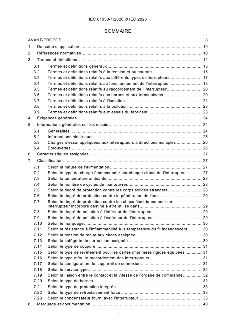
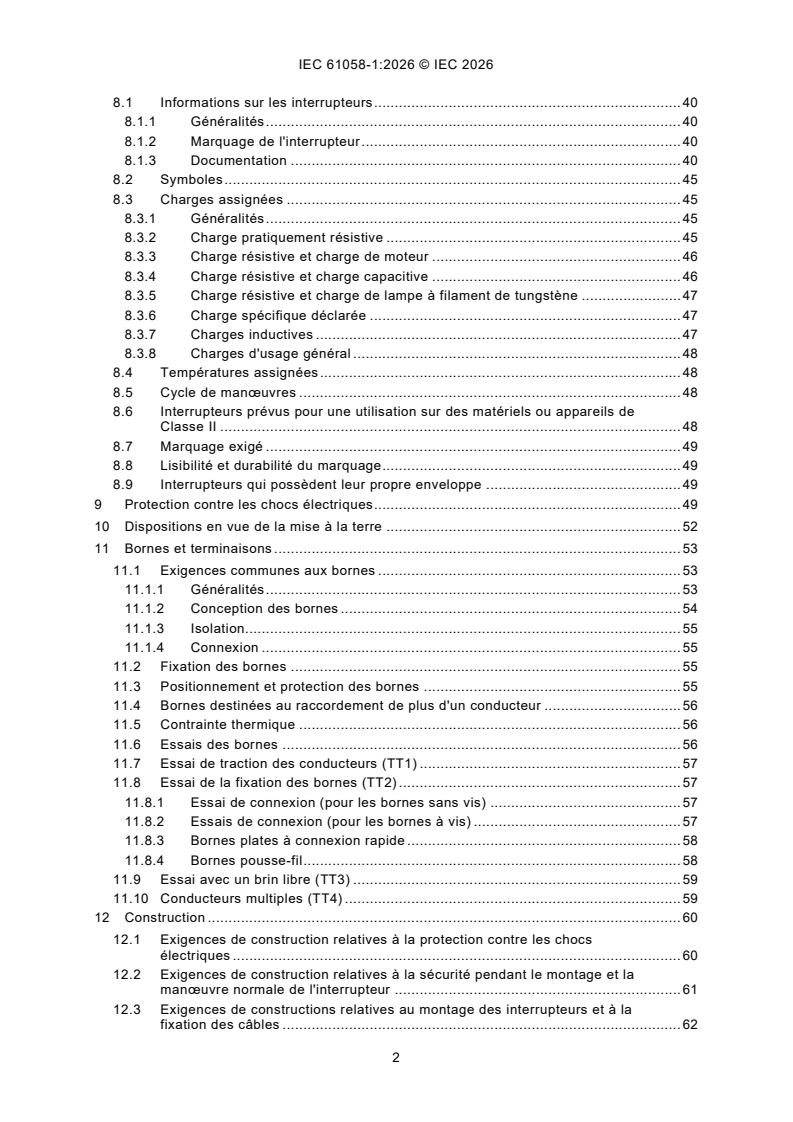
IEC 61058-1:2026 - Interrupteurs pour appareils - Partie 1: Exigences générales
Overview
IEC 61058-1:2026, titled Switches for appliances - Part 1: General requirements, is an essential international standard from the International Electrotechnical Commission (IEC). This fifth edition establishes the safety, performance, and testing criteria for switches and switching devices intended to control electrical appliances and equipment for household or similar applications.
The standard applies to switches with the following parameters:
- Rated voltage not exceeding 600 V
- Rated current not exceeding 63 A
IEC 61058-1:2026 completely replaces the fourth edition (2016), featuring significant updates to meet advancing technology and market requirements. Manufacturers, test laboratories, certification bodies, and product designers rely on this document to ensure the safety, durability, and conformity of switches used in domestic appliances.
Key Topics
IEC 61058-1:2026 comprehensively addresses the general requirements, safety aspects, classification, and test methods for appliance switches, including:
- Scope Expansion: Now covers switches rated up to 600 V.
- Ground-Fuse Requirements: New provisions specify design and testing (Clause 17).
- DC Arc Extinction Testing: Enhanced focus on switch performance with DC loads (Annex P, Clause 17).
- Classification and Ratings: Addressed in updated tables for greater clarity.
- Safety and Protection: Includes guidelines on protection against electric shock, ingress of solid objects and water, and insulation requirements.
- Marking and Documentation: Defines essential labeling, instructions, and compliance documentation.
- Terminal and Connection Requirements: Comprehensive requirements and test methods for various terminal designs.
- Endurance and Mechanical Strength: Specifies endurance cycles, impact, pull, and push tests for reliability.
- Heating and Thermal Stress: Sets limits and test conditions to minimize risk of overheating.
- Electromagnetic Compatibility (EMC): Outlines immunity and emission tests to prevent electrical disturbances.
Applications
IEC 61058-1:2026 is vital for a wide range of appliance switches and switching devices, ensuring products meet international safety and quality standards. Typical applications include:
- Household Appliances: Such as washing machines, refrigerators, ovens, small kitchen devices, and fans.
- Similar Equipment: Switches for tools, personal care devices, or hobby equipment intended for domestic settings.
- Commercial and Institutional Environments: For appliances installed in offices, schools, or light industry if technical parameters match the scope.
- Global Product Compliance: Used by manufacturers to demonstrate conformity with international and national safety regulations, facilitating market access.
Adhering to IEC 61058-1:2026 supports product reliability and helps mitigate risks during operation, installation, and maintenance.
Related Standards
IEC 61058-1:2026 aligns with global appliance safety frameworks and references further IEC and international standards, such as:
- IEC 60335 Series: Safety requirements for household and similar electrical appliances.
- IEC 60947 Series: Low-voltage switchgear and controlgear, relevant for switches with higher demands.
- IEC 60730 Series: Automatic electrical controls for household and similar use.
- IEC 61058-2-x: Particular requirements for specific switch types, complementing the general requirements in Part 1.
- IEC 60529: Degrees of protection provided by enclosures (IP code).
- IEC 61000 Series: Electromagnetic compatibility (EMC) standards.
Proper selection and implementation of IEC 61058-1:2026 help achieve compliance, interoperability, and safety in appliance switch design and usage globally.
Relations
- Effective Date
- 05-Sep-2023
Buy Documents
IEC 61058-1:2026 - Switches for appliances - Part 1: General requirements
REDLINE IEC 61058-1:2026 RLV - Switches for appliances - Part 1: General requirements
IEC 61058-1:2026 - Interrupteurs pour appareils - Partie 1: Exigences générales
Get Certified
Connect with accredited certification bodies for this standard

IMQ S.p.A. (Certification)
Italian electrical product certification.

SLG Prüf- und Zertifizierungs GmbH
German testing and certification body.

UL Solutions
Global safety science company with testing, inspection and certification.
Sponsored listings
Frequently Asked Questions
IEC 61058-1:2026 is a standard published by the International Electrotechnical Commission (IEC). Its full title is "Switches for appliances - Part 1: General requirements". This standard covers: IEC 61058-1:2026 applies to switches or switching devices for appliances. The switches are intended to control electrical appliances and other equipment for household or similar purposes with a rated voltage not exceeding 600 V and a rated current not exceeding 63 A. This fifth edition cancels and replaces the fourth edition published in 2016. This edition constitutes a technical revision. This edition includes the following significant technical changes with respect to the previous edition: a) Extension to 600 V in the scope; b) Add requirements on ground-fuse (Clause 17); c) DC arc extinction test (Annex P and Clause 17); d) Table 5 re-arranged to line-up with classifications; e) Table 6 correction due to inhomogeneous values; f) Deletion of X3 capacitors in classification and in Table 19.
IEC 61058-1:2026 applies to switches or switching devices for appliances. The switches are intended to control electrical appliances and other equipment for household or similar purposes with a rated voltage not exceeding 600 V and a rated current not exceeding 63 A. This fifth edition cancels and replaces the fourth edition published in 2016. This edition constitutes a technical revision. This edition includes the following significant technical changes with respect to the previous edition: a) Extension to 600 V in the scope; b) Add requirements on ground-fuse (Clause 17); c) DC arc extinction test (Annex P and Clause 17); d) Table 5 re-arranged to line-up with classifications; e) Table 6 correction due to inhomogeneous values; f) Deletion of X3 capacitors in classification and in Table 19.
IEC 61058-1:2026 is classified under the following ICS (International Classification for Standards) categories: 29.120.40 - Switches. The ICS classification helps identify the subject area and facilitates finding related standards.
IEC 61058-1:2026 has the following relationships with other standards: It is inter standard links to IEC 61058-1:2016. Understanding these relationships helps ensure you are using the most current and applicable version of the standard.
IEC 61058-1:2026 is available in PDF format for immediate download after purchase. The document can be added to your cart and obtained through the secure checkout process. Digital delivery ensures instant access to the complete standard document.
Standards Content (Sample)
IEC 61058-1 ®
Edition 5.0 2026-07
INTERNATIONAL
STANDARD
Switches for appliances -
Part 1: General requirements
ICS 29.120.40 ISBN 978-2-8327-1361-7
All rights reserved. Unless otherwise specified, no part of this publication may be reproduced or utilized in any form or
by any means, electronic or mechanical, including photocopying and microfilm, without permission in writing from either
IEC or IEC's member National Committee in the country of the requester. If you have any questions about IEC copyright
or have an enquiry about obtaining additional rights to this publication, please contact the address below or your local
IEC member National Committee for further information.
IEC Secretariat Tel.: +41 22 919 02 11
3, rue de Varembé info@iec.ch
CH-1211 Geneva 20 www.iec.ch
Switzerland
About the IEC
The International Electrotechnical Commission (IEC) is the leading global organization that prepares and publishes
International Standards for all electrical, electronic and related technologies.
About IEC publications
The technical content of IEC publications is kept under constant review by the IEC. Please make sure that you have the
latest edition, a corrigendum or an amendment might have been published.
IEC publications search - IEC Products & Services Portal - products.iec.ch
webstore.iec.ch/advsearchform Discover our powerful search engine and read freely all the
The advanced search enables to find IEC publications by a publications previews, graphical symbols and the glossary.
variety of criteria (reference number, text, technical With a subscription you will always have access to up to date
committee, …). It also gives information on projects, content tailored to your needs.
replaced and withdrawn publications.
Electropedia - www.electropedia.org
The world's leading online dictionary on electrotechnology,
IEC Just Published - webstore.iec.ch/justpublished
Stay up to date on all new IEC publications. Just Published containing more than 22 500 terminological entries in English
details all new publications released. Available online and and French, with equivalent terms in 25 additional languages.
once a month by email. Also known as the International Electrotechnical Vocabulary
(IEV) online.
IEC Customer Service Centre - webstore.iec.ch/csc
If you wish to give us your feedback on this publication or
need further assistance, please contact the Customer
Service Centre: sales@iec.ch.
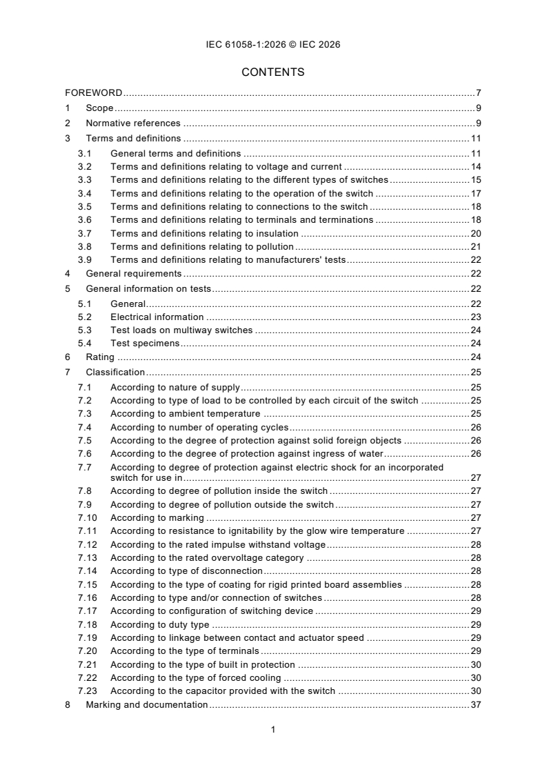
CONTENTS
FOREWORD . 7
1 Scope . 9
2 Normative references . 9
3 Terms and definitions . 11
3.1 General terms and definitions . 11
3.2 Terms and definitions relating to voltage and current . 14
3.3 Terms and definitions relating to the different types of switches . 15
3.4 Terms and definitions relating to the operation of the switch . 17
3.5 Terms and definitions relating to connections to the switch . 18
3.6 Terms and definitions relating to terminals and terminations . 18
3.7 Terms and definitions relating to insulation . 20
3.8 Terms and definitions relating to pollution . 21
3.9 Terms and definitions relating to manufacturers' tests . 22
4 General requirements . 22
5 General information on tests . 22
5.1 General . 22
5.2 Electrical information . 23
5.3 Test loads on multiway switches . 24
5.4 Test specimens . 24
6 Rating . 24
7 Classification . 25
7.1 According to nature of supply . 25
7.2 According to type of load to be controlled by each circuit of the switch . 25
7.3 According to ambient temperature . 25
7.4 According to number of operating cycles . 26
7.5 According to the degree of protection against solid foreign objects . 26
7.6 According to the degree of protection against ingress of water . 26
7.7 According to degree of protection against electric shock for an incorporated
switch for use in . 27
7.8 According to degree of pollution inside the switch . 27
7.9 According to degree of pollution outside the switch . 27
7.10 According to marking . 27
7.11 According to resistance to ignitability by the glow wire temperature . 27
7.12 According to the rated impulse withstand voltage . 28
7.13 According to the rated overvoltage category . 28
7.14 According to type of disconnection . 28
7.15 According to the type of coating for rigid printed board assemblies . 28
7.16 According to type and/or connection of switches . 28
7.17 According to configuration of switching device . 29
7.18 According to duty type . 29
7.19 According to linkage between contact and actuator speed . 29
7.20 According to the type of terminals . 29
7.21 According to the type of built in protection . 30
7.22 According to the type of forced cooling . 30
7.23 According to the capacitor provided with the switch . 30
8 Marking and documentation . 37
8.1 Switch information . 37
8.1.1 General . 37
8.1.2 By switch marking . 37
8.1.3 By documentation . 38
8.2 Symbols . 41
8.3 Load rating . 41
8.3.1 General . 41
8.3.2 Substantially resistive load . 41
8.3.3 Resistive load and motor load . 42
8.3.4 Resistive load and capacitive load . 42
8.3.5 Resistive load and tungsten filament lamp load . 43
8.3.6 Declared specific load . 43
8.3.7 Inductive loads . 43
8.3.8 General purpose loads . 44
8.4 Temperature rating . 44
8.5 Operating cycles . 44
8.6 Switches intended for use in Class II equipment or appliances . 44
8.7 Required marking. 44
8.8 Legibility and durability of marking . 45
8.9 Switches with their own enclosure. 45
9 Protection against electric shock . 45
10 Provision for earthing . 47
11 Terminals and terminations. 49
11.1 Common requirements to terminals . 49
11.1.1 General . 49
11.1.2 Design of terminals . 50
11.1.3 Insulation . 50
11.1.4 Connection . 50
11.2 Fixing of terminals . 50
11.3 Location and shielding of terminals . 51
11.4 Terminals for interconnection of more than one conductors. 51
11.5 Thermal stress . 51
11.6 Terminal tests . 51
11.7 Conductor escape test (TT1) . 52
11.8 Terminal displacement test (TT2) . 53
11.8.1 Connection test (for screwless terminals) . 53
11.8.2 Connection tests (for screw-type terminals) . 53
11.8.3 Flat quick-connect termination . 53
11.8.4 Push in terminals . 54
11.9 Strand escape test (TT3) . 54
11.10 Multiple conductors (TT4) . 55
12 Construction . 55
12.1 Constructional requirements relating to protection against electric shock . 55
12.2 Constructional requirements relating to safety during mounting and normal
operation of the switch . 56
12.3 Constructional requirements relating to the mounting of switches and to the
attachment of cords . 57
13 Mechanism . 57
14 Protection against ingress of solid foreign objects, ingress of water and humid
conditions . 58
14.1 Protection against ingress of solid foreign objects . 58
14.2 Protection against ingress of water . 58
14.3 Protection against humid conditions . 59
15 Insulation resistance and dielectric strength . 60
15.1 General requirements . 60
15.2 Measurement of insulation resistance . 60
15.3 Insulation test voltage . 61
16 Heating . 62
16.1 General requirements . 62
16.2 Contacts and terminals . 62
16.3 Other parts . 63
16.4 Heating test . 63
16.4.1 Test specimen . 63
16.4.2 Conductor Connections . 63
16.4.3 Test preparation setup . 63
16.4.4 Test procedure . 63
16.4.5 Evaluation of compliance . 64
17 Endurance . 64
18 Mechanical strength . 65
18.1 General requirements . 65
18.2 Impact . 65
18.3 Pull . 65
18.4 Push . 66
19 Screws, current-carrying parts and connections . 66
19.1 General requirements for electrical connections . 66
19.2 Screwed connections . 66
19.3 Current-carrying parts . 69
20 Clearances, creepage distances, solid insulation and coatings of rigid printed
board assemblies . 69
20.1 General requirements . 69
20.2 Clearances . 70
20.2.1 General . 70
20.2.2 Clearances for basic insulation . 70
20.2.3 Clearances for functional insulation . 70
20.2.4 Clearances for supplementary insulation . 70
20.2.5 Clearances for reinforced insulation . 71
20.3 Clearances for disconnection . 71
20.3.1 Electronic disconnection . 71
20.3.2 Micro-disconnection . 71
20.3.3 Full disconnection . 72
20.4 Creepage distances . 72
20.4.1 General . 72
20.4.2 Creepage distances for basic insulation . 72
20.4.3 Creepage distances for functional insulation . 73
20.4.4 Creepage distances for supplementary insulation . 74
20.4.5 Creepage distances for reinforced insulation . 74
20.4.6 Creepage distances for disconnection . 74
20.5 Solid insulation . 75
20.6 Coatings of rigid printed board assemblies . 75
20.6.1 General . 75
20.6.2 Type 1 coating . 75
20.6.3 Type 2 coating . 76
21 Resistance to heat and abnormal heat . 76
21.1 General . 76
21.2 Resistance to heat . 76
21.3 Resistance to abnormal heat . 77
22 Resistance to rusting . 78
23 Abnormal operation and fault conditions for switches. 78
24 Components for switches . 78
24.1 General requirements . 78
24.2 Protective devices . 79
24.2.1 General . 79
24.2.2 Fuses . 79
24.2.3 Cut-outs . 79
24.2.4 Protective devices which only decrease the current (for example PTC
resistors) . 81
24.2.5 Fusing resistors . 81
24.3 Capacitors . 81
24.4 Resistors . 82
25 EMC requirements . 82
25.1 General . 82
25.2 Immunity . 82
25.2.1 General . 82
25.2.2 Voltage dips and short interruptions . 83
25.2.3 Surge immunity test . 83
25.2.4 Electrical fast transient test . 83
25.2.5 Electrostatic discharge test . 84
25.2.6 Radiated electromagnetic field test . 84
25.2.7 Power-frequency magnetic field test . 85
25.3 Emission . 85
25.3.1 Low-frequency emission . 85
25.3.2 Radio-frequency emission . 85
Annex A (normative) Measurement of clearances and creepage distances . 100
Annex B (informative) Diagram for the dimensioning of clearances and creepage
distances . 105
Annex C (normative) Proof tracking test . 106
Annex D (informative) Switch application guide . 107
D.1 General . 107
D.2 Resistive load current ratings . 107
D.3 Resistive and/or motor load current ratings . 107
D.4 Combination capacitive and resistive load ratings . 108
D.5 Declared specific load ratings . 108
D.6 Current ratings not exceeding 20 mA . 108
D.7 General purpose load . 108
Annex E (normative) Relation between rated impulse withstand voltage, rated voltage
and overvoltage category . 109
Annex F (normative) Pollution degree . 110
Annex G (normative) Impulse voltage test . 111
Annex H (normative) Altitude correction factors . 112
Annex I (normative) Types of coatings for rigid printed board assemblies . 113
Annex J (normative) Measuring the insulation distance of a coated printed board with
type 1 coating . 114
Annex K (normative) Routine tests . 115
Annex L (informative) Sampling tests . 116
L.1 General . 116
L.2 General considerations . 116
L.3 Tests . 116
Annex M (normative) Switch families . 118
M.1 Overview . 118
M.2 General . 118
M.3 Guidelines for selection of switches in switch families for testing . 119
Annex N (informative) Dimensions of tabs forming part of a switch . 120
Annex O (informative) Common end product standards. 121
Annex P (informative) Background of DC arc extinction test (17.5.7 TC11) . 122
P.1 General . 122
P.2 Test current sequence . 122
P.3 Arc extinction time . 122
Bibliography . 123
Figure 1 – Examples of pillar terminals . 87
Figure 2 – Examples of screw terminals and stud terminals . 88
Figure 3 – Examples of saddle terminals . 89
Figure 4 – Examples of lug terminals . 89
Figure 5 – Examples of mantle terminals . 90
Figure 6 – Examples of screwless terminals . 91
Figure 7 – Example of female (test) connector of flat quick-connect terminations . 92
Figure 8 – Circuit for capacitive load test and simulated tungsten filament lamp load
test for AC circuits . 93
Figure 9 – Circuit for capacitive load test and simulated lamp load test for DC circuits . 94
Figure 10 – Values of the capacitive load test circuit for test of switches rated 10/100 A
250 V AC . 95
Figure 11 – Mounting device for the impact tests . 96
Figure 12 – Continuous duty – Duty type S1 (see 7.18.1) . 97
Figure 13 – Short-time duty – Duty type S2 (see 7.18.2) . 97
Figure 14 – Intermittent periodic duty – Duty-type S3 (see 7.18.3) . 98
Figure 15 – Diagram for heating test . 98
Figure 16 – Diagram for endurance test . 99
Figure A.1 – Example 1 . 101
Figure A.2 – Example 2 . 101
Figure A.3 – Example 3 . 101
Figure A.4 – Example 4 . 101
Figure A.5 – Example 5 . 102
Figure A.6 – Example 6 . 102
Figure A.7 – Example 7 . 102
Figure A.8 – Example 8 . 103
Figure A.9 – Example 9 . 103
Figure A.10 – Example 10 . 104
Figure A.11 – Example 11 . 104
Figure B.1 – Diagram for the dimensioning of clearances and creepage distances . 105
Figure J.1 – Measurement of the insulation distance . 114
Figure P.1 – Circuit conditions for DC arc extinction testing . 122
Table 1 – Test loads for multiway switches . 24
Table 2 – Type and connection of switches . 31
Table 3 – Switch information and loads placed in groups . 38
Table 4 – Resistive current carried by the terminal and related cross-sectional areas of
terminals for unprepared conductors . 49
Table 5 – Terminal type test for prepared and unprepared conductors . 51
Table 6 – Insertion and withdrawal force . 53
Table 7 – Pulling forces for screw-type and push-in terminals . 54
Table 8 – Minimum insulation resistance . 61
Table 9 – Dielectric strength . 62
Table 10 – Minimum values of pull force . 65
Table 11 – Torque values . 68
Table 12 – Torque values for screwed glands . 68
Table 13 – Minimum clearances for basic insulation . 71
Table 14 – Minimum creepage distances for basic insulation . 73
Table 15 – Minimum creepage distances for functional insulation . 73
Table 16 – Test levels and conditions . 75
Table 17 – Test temperature for ball pressure test . 77
Table 18 – Test Temperature for glow wire test . 78
Table 19 – Minimum requirements for capacitors . 82
Table 20 – Test levels and duration for voltage dips and short interruptions . 83
Table 21 – Fast transient bursts . 84
Table A.1 – Minimum values for distances with specific pollution degrees . 100
Table E.1 – Rated impulse withstand voltage for switches energized directly from the
low voltage mains . 109
Table G.1 – Test voltages for verifying clearances at sea-level . 111
Table H.1 – Altitude correction factors . 112
INTERNATIONAL ELECTROTECHNICAL COMMISSION
____________
Switches for appliances -
Part 1: General requirements
FOREWORD
1) The International Electrotechnical Commission (IEC) is a worldwide organization for standardization comprising
all national electrotechnical committees (IEC National Committees). The object of IEC is to promote international
co-operation on all questions concerning standardization in the electrical and electronic fields. To this end and
in addition to other activities, IEC publishes International Standards, Technical Specifications, Technical Reports,
Publicly Available Specifications (PAS) and Guides (hereafter referred to as “IEC Publication(s)”). Their
preparation is entrusted to technical committees; any IEC National Committee interested in the subject dealt with
may participate in this preparatory work. International, governmental and non-governmental organizations liaising
with the IEC also participate in this preparation. IEC collaborates closely with the International Organization for
Standardization (ISO) in accordance with conditions determined by agreement between the two organizations.
2) The formal decisions or agreements of IEC on technical matters express, as nearly as possible, an international
consensus of opinion on the relevant subjects since each technical committee has representation from all
interested IEC National Committees.
3) IEC Publications have the form of recommendations for international use and are accepted by IEC National
Committees in that sense. While all reasonable efforts are made to ensure that the technical content of IEC
Publications is accurate, IEC cannot be held responsible for the way in which they are used or for any
misinterpretation by any end user.
4) In order to promote international uniformity, IEC National Committees undertake to apply IEC Publications
transparently to the maximum extent possible in their national and regional publications. Any divergence between
any IEC Publication and the corresponding national or regional publication shall be clearly indicated in the latter.
5) IEC itself does not provide any attestation of conformity. Independent certification bodies provide conformity
assessment services and, in some areas, access to IEC marks of conformity. IEC is not responsible for any
services carried out by independent certification bodies.
6) All users should ensure that they have the latest edition of this publication.
7) No liability shall attach to IEC or its directors, employees, servants or agents including individual experts and
members of its technical committees and IEC National Committees for any personal injury, property damage or
other damage of any nature whatsoever, whether direct or indirect, or for costs (including legal fees) and
expenses arising out of the publication, use of, or reliance upon, this IEC Publication or any other IEC
Publications.
8) Attention is drawn to the Normative references cited in this publication. Use of the referenced publications is
indispensable for the correct application of this publication.
9) IEC draws attention to the possibility that the implementation of this document may involve the use of (a)
patent(s). IEC takes no position concerning the evidence, validity or applicability of any claimed patent rights in
respect thereof. As of the date of publication of this document, IEC had not received notice of (a) patent(s), which
may be required to implement this document. However, implementers are cautioned that this may not represent
the latest information, which may be obtained from the patent database available at https://patents.iec.ch. IEC
shall not be held responsible for identifying any or all such patent rights.
IEC 61058-1has been prepared by subcommittee 23J: Switches for appliances, of IEC technical
committee 23: Electrical accessories. It is an International Standard.
This fifth edition cancels and replaces the fourth edition published in 2016. This edition
constitutes a technical revision.
This edition includes the following significant technical changes with respect to the previous
edition:
a) Extension to 600 V in the scope;
b) Add requirements on ground-fuse (Clause 17);
c) DC arc extinction test (Annex P and Clause 17);
d) Table 5 re-arranged to line-up with classifications;
e) Table 6 correction due to inhomogeneous values;
f) Deletion of X3 capacitors in classification and in Table 19.
The text of this International Standard is based on the following documents:
Draft Report on voting
23J/494/FDIS 23J/499/RVD
Full information on the voting for its approval can be found in the report on voting indicated in
the above table.
The language used for the development of this International Standard is English.
This document was drafted in accordance with ISO/IEC Directives, Part 2, and developed in
accordance with ISO/IEC Directives, Part 1 and ISO/IEC Directives, IEC Supplement, available
at www.iec.ch/members_experts/refdocs. The main document types developed by IEC are
described in greater detail at www.iec.ch/publications.
A list of all parts in the IEC 61058 series, published under the general title Switches for
appliances, can be found on the IEC website.
In this document, the following print types are used:
– requirements proper: roman type;
– test specifications: italic type;
– explanatory matter: in smaller roman type.
The committee has decided that the contents of this document will remain unchanged until the
stability date indicated on the IEC website under webstore.iec.ch in the data related to the
specific document. At this date, the document will be
– reconfirmed,
– withdrawn, or
– revised.
1 Scope
This part of IEC 61058 applies to switches or switching devices for appliances. The switches
are intended to control electrical appliances and other equipment for household or similar
purposes with a rated voltage not exceeding 600 V and a rated current not exceeding 63 A.
In the IEC 61058 series the terms "switching devices" and "switches" are used interchangeably.
Switches for appliances are intended to be operated by
– a person via an actuating member,
– indirect actuation,
– an actuating sensing unit.
Transmission of a signal between the actuating member or sensing unit and the switch can be
connected by optical, acoustic, thermal, electrical or other relevant connection and can include
remote controlled units.
This document applies to switches for appliances with additional control functions provided by
the switch using electronic circuits.
This document applies to circuitry when evaluated with a switch and necessary for the switching
function.
This part document applies in general to switches for appliances in conjunction with the
following parts:
– Part 1-1: Requirements for mechanical switches, and/or
– Part 1-2: Requirements for electronic switches.
This document does not apply to switches covered by:
– IEC 60669 (all parts), Switches for household and similar fixed-electrical installations, and
– IEC 60730 (all parts), Automatic electrical controls.
NOTE 1 Attention is drawn to the fact that the end product standards for appliances can contain additional or
alternative requirements for switches (see Annex O).
NOTE 2 Throughout this document, the word "appliance" means "appliance or equipment".
2 Normative references
The following documents are referred to in the text in such a way that some or all of their content
constitutes requirements of this document. For dated references, only the edition cited applies.
For undated references, the latest edition of the referenced document (including any
amendments) applies.
IEC 60127 (all parts), Miniature fuses
IEC 60269-3, Low-voltage fuses - Part 3: Supplementary requirements for fuses for use by
unskilled persons (fuses mainly for household or similar applications) - Examples of
standardized systems of fuses A to F
IEC 60384-14, Fixed capacitors for use in electronic equipment - Part 14: Sectional
specification - Fixed capacitors for electromagnetic interference suppression and connection to
the supply mains
IEC 60417, Graphical symbols for use on equipment (available at: http://www.graphical-
symbols.info/equipment)
IEC 60529:1989, Degree of protection provided by enclosures (IP code)
IEC 60529:1989/AMD1:1999
IEC 60529:1989/AMD2:2013
IEC 60617, Graphical symbols for diagrams
IEC 60664-3:2016, Insulation coordination for equipment within low-voltage systems - Part 3:
Use of coating, potting or moulding for protection against pollution
IEC 60691, Thermal-links - Requirements and application guide
IEC 60695-2-11, Fire hazard testing - Part 2-11: Glowing/hot-wire based test methods -
Glow-wire flammability test method for end-products
IEC 60695-10-2, Fire hazard testing - Part 10-2: Abnormal heat - Ball pressure test method
IEC 60695-11-10, Fire hazard testing - Part 11-10: Test flames - 50 W horizontal and vertical
flame test methods
IEC 606
...
IEC 61058-1 ®
Edition 5.0 2026-07
INTERNATIONAL
STANDARD
REDLINE VERSION
Switches for appliances -
Part 1: General requirements
ICS 29.120.40 ISBN 978-2-8327-1432-4
All rights reserved. Unless otherwise specified, no part of this publication may be reproduced or utilized in any form or
by any means, electronic or mechanical, including photocopying and microfilm, without permission in writing from either
IEC or IEC's member National Committee in the country of the requester. If you have any questions about IEC copyright
or have an enquiry about obtaining additional rights to this publication, please contact the address below or your local
IEC member National Committee for further information.
IEC Secretariat Tel.: +41 22 919 02 11
3, rue de Varembé info@iec.ch
CH-1211 Geneva 20 www.iec.ch
Switzerland
About the IEC
The International Electrotechnical Commission (IEC) is the leading global organization that prepares and publishes
International Standards for all electrical, electronic and related technologies.
About IEC publications
The technical content of IEC publications is kept under constant review by the IEC. Please make sure that you have the
latest edition, a corrigendum or an amendment might have been published.
IEC publications search - IEC Products & Services Portal - products.iec.ch
webstore.iec.ch/advsearchform Discover our powerful search engine and read freely all the
The advanced search enables to find IEC publications by a publications previews, graphical symbols and the glossary.
variety of criteria (reference number, text, technical With a subscription you will always have access to up to date
committee, …). It also gives information on projects, content tailored to your needs.
replaced and withdrawn publications.
Electropedia - www.electropedia.org
The world's leading online dictionary on electrotechnology,
IEC Just Published - webstore.iec.ch/justpublished
Stay up to date on all new IEC publications. Just Published containing more than 22 500 terminological entries in English
details all new publications released. Available online and and French, with equivalent terms in 25 additional languages.
once a month by email. Also known as the International Electrotechnical Vocabulary
(IEV) online.
IEC Customer Service Centre - webstore.iec.ch/csc
If you wish to give us your feedback on this publication or
need further assistance, please contact the Customer
Service Centre: sales@iec.ch.
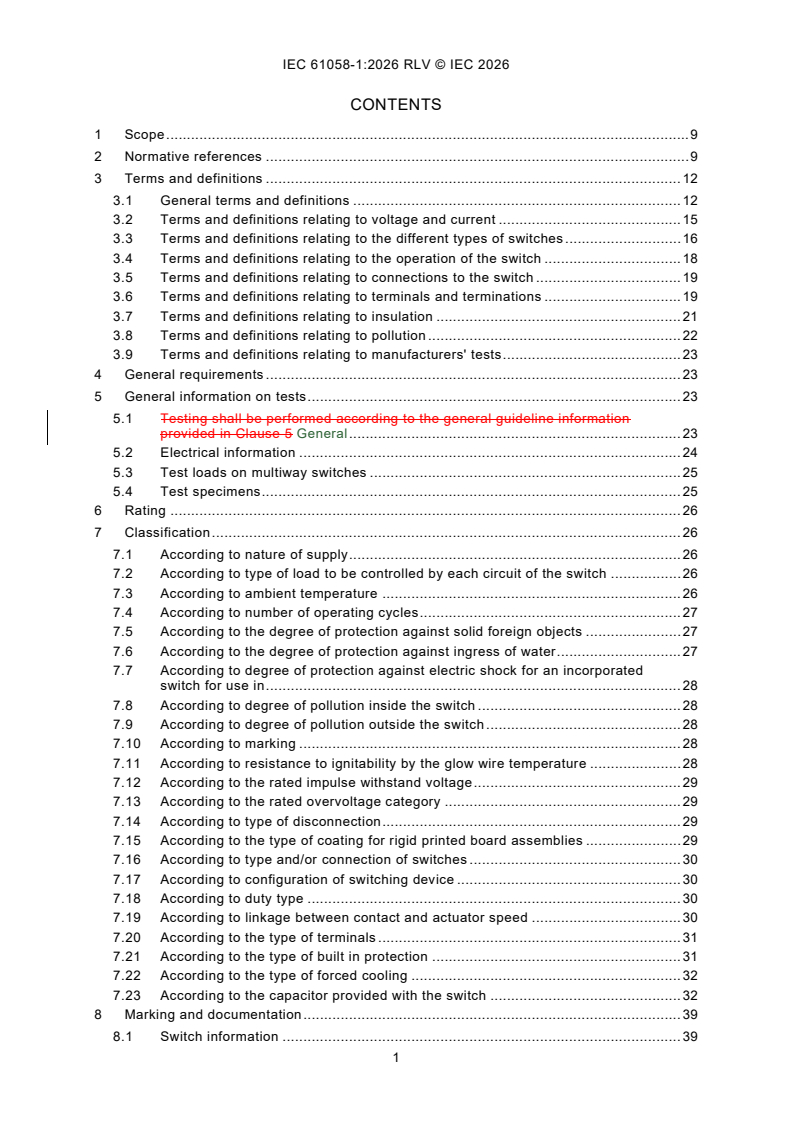
CONTENTS
1 Scope . 9
2 Normative references . 9
3 Terms and definitions . 12
3.1 General terms and definitions . 12
3.2 Terms and definitions relating to voltage and current . 15
3.3 Terms and definitions relating to the different types of switches . 16
3.4 Terms and definitions relating to the operation of the switch . 18
3.5 Terms and definitions relating to connections to the switch . 19
3.6 Terms and definitions relating to terminals and terminations . 19
3.7 Terms and definitions relating to insulation . 21
3.8 Terms and definitions relating to pollution . 22
3.9 Terms and definitions relating to manufacturers' tests . 23
4 General requirements . 23
5 General information on tests . 23
5.1 Testing shall be performed according to the general guideline information
provided in Clause 5 General . 23
5.2 Electrical information . 24
5.3 Test loads on multiway switches . 25
5.4 Test specimens . 25
6 Rating . 26
7 Classification . 26
7.1 According to nature of supply . 26
7.2 According to type of load to be controlled by each circuit of the switch . 26
7.3 According to ambient temperature . 26
7.4 According to number of operating cycles . 27
7.5 According to the degree of protection against solid foreign objects . 27
7.6 According to the degree of protection against ingress of water . 27
7.7 According to degree of protection against electric shock for an incorporated
switch for use in . 28
7.8 According to degree of pollution inside the switch . 28
7.9 According to degree of pollution outside the switch . 28
7.10 According to marking . 28
7.11 According to resistance to ignitability by the glow wire temperature . 28
7.12 According to the rated impulse withstand voltage . 29
7.13 According to the rated overvoltage category . 29
7.14 According to type of disconnection . 29
7.15 According to the type of coating for rigid printed board assemblies . 29
7.16 According to type and/or connection of switches . 30
7.17 According to configuration of switching device . 30
7.18 According to duty type . 30
7.19 According to linkage between contact and actuator speed . 30
7.20 According to the type of terminals . 31
7.21 According to the type of built in protection . 31
7.22 According to the type of forced cooling . 32
7.23 According to the capacitor provided with the switch . 32
8 Marking and documentation . 39
8.1 Switch information . 39
8.1.1 General . 39
8.1.2 By switch marking . 39
8.1.3 By documentation . 39
8.2 Symbols . 42
8.3 Load rating . 43
8.3.1 General . 43
8.3.2 Substantially resistive load . 43
8.3.3 Resistive load and motor load . 43
8.3.4 Resistive load and capacitive load . 44
8.3.5 Resistive load and tungsten filament lamp load . 44
8.3.6 Declared specific load . 44
8.3.7 Inductive loads . 45
8.3.8 General purpose loads . 45
8.4 Temperature rating . 45
8.5 Operating cycles . 46
8.6 Switches intended for use in Class II equipment or appliances . 46
8.7 Required marking. 46
8.8 Legibility and durability of marking . 46
8.9 Switches with their own enclosure. 46
9 Protection against electric shock . 47
10 Provision for earthing . 48
11 Terminals and terminations. 50
11.1 Common requirements to terminals . 50
11.1.1 General . 50
11.1.2 Design of terminals . 51
11.1.3 Insulation . 51
11.1.4 Connection . 51
11.2 Fixing of terminals . 52
11.3 Location and shielding of terminals . 52
11.4 Terminals for interconnection of more than one conductors. 52
11.5 Thermal stress . 52
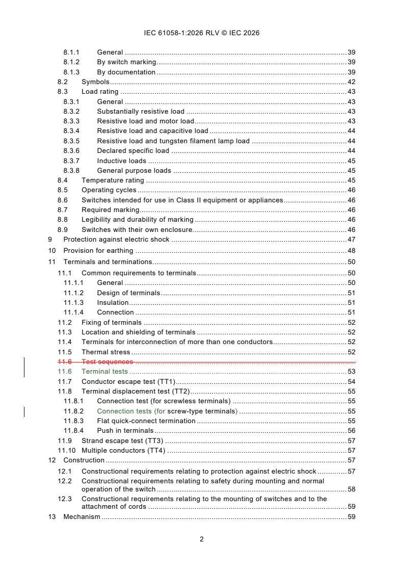
11.6 Test sequences .
11.6 Terminal tests . 53
11.7 Conductor escape test (TT1) . 54
11.8 Terminal displacement test (TT2) . 55
11.8.1 Connection test (for screwless terminals) . 55
11.8.2 Connection tests (for screw-type terminals) . 55
11.8.3 Flat quick-connect termination . 55
11.8.4 Push in terminals . 56
11.9 Strand escape test (TT3) . 57
11.10 Multiple conductors (TT4) . 57
12 Construction . 57
12.1 Constructional requirements relating to protection against electric shock . 57
12.2 Constructional requirements relating to safety during mounting and normal
operation of the switch . 58
12.3 Constructional requirements relating to the mounting of switches and to the
attachment of cords . 59
13 Mechanism . 59
14 Protection against ingress of solid foreign objects, ingress of water and humid
conditions . 60
14.1 Protection against ingress of solid foreign objects . 60
14.2 Protection against ingress of water . 61
14.3 Protection against humid conditions . 62
15 Insulation resistance and dielectric strength . 62
15.1 General requirements . 62
15.2 Measurement of insulation resistance . 63
15.3 Insulation test voltage . 63
16 Heating . 64
16.1 General requirements . 64
16.2 Contacts and terminals . 64
16.3 Other parts . 65
16.4 Heating test . 65
16.4.1 Test specimen . 65
16.4.2 Conductor Connections . 65
16.4.3 Test preparation setup . 65
16.4.4 Test procedure . 65
16.4.5 Evaluation of compliance . 66
17 Endurance . 66
18 Mechanical strength . 67
18.1 General requirements . 67
18.2 Impact . 67
18.3 Pull . 67
18.4 Push . 68
19 Screws, current-carrying parts and connections . 68
19.1 General requirements for electrical connections . 68
19.2 Screwed connections . 68
19.3 Current-carrying parts . 71
20 Clearances, creepage distances, solid insulation and coatings of rigid printed
board assemblies . 71
20.1 General requirements . 71
20.2 Clearances . 72
20.2.1 General . 72
20.2.2 Clearances for basic insulation . 72
20.2.3 Clearances for functional insulation . 72
20.2.4 Clearances for supplementary insulation . 72
20.2.5 Clearances for reinforced insulation . 73
20.3 Clearances for disconnection . 73
20.3.1 Electronic disconnection . 73
20.3.2 Micro-disconnection . 73
20.3.3 Full disconnection . 74
20.4 Creepage distances . 74
20.4.1 General . 74
20.4.2 Creepage distances for basic insulation . 74
20.4.3 Creepage distances for functional insulation . 75
20.4.4 Creepage distances for supplementary insulation . 77
20.4.5 Creepage distances for reinforced insulation . 77
20.4.6 Creepage distances for disconnection . 77
20.5 Solid insulation . 77
20.6 Coatings of rigid printed board assemblies . 78
20.6.1 General . 78
20.6.2 Type 1 coating . 78
20.6.3 Type 2 coating . 78
21 Fire hazard Resistance to heat and abnormal heat . 79
21.1 General . 79
21.2 Resistance to heat . 79
21.3 Resistance to abnormal heat . 80
22 Resistance to rusting . 81
23 Abnormal operation and fault conditions for switches. 82
24 Components for switches . 82
24.1 General requirements . 82
24.2 Protective devices . 82
24.2.1 General . 82
24.2.2 Fuses . 82
24.2.3 Cut-outs . 83
24.2.4 Protective devices which only decrease the current (for example PTC
resistors) . 84
24.2.5 Fusing resistors . 84
24.3 Capacitors . 84
24.4 Resistors . 85
25 EMC requirements . 86
25.1 General . 86
25.2 Immunity . 86
25.2.1 General . 86
25.2.2 Voltage dips and short interruptions . 86
25.2.3 Surge immunity test . 87
25.2.4 Electrical fast transient test . 87
25.2.5 Electrostatic discharge test . 88
25.2.6 Radiated electromagnetic field test . 88
25.2.7 Power-frequency magnetic field test . 88
25.3 Emission . 89
25.3.1 Low-frequency emission . 89
25.3.2 Radio-frequency emission . 89
Annex A (normative) Measurement of clearances and creepage distances . 103
Annex B (informative) Diagram for the dimensioning of clearances and creepage
distances . 112
Annex C (normative) Proof tracking test . 113
Annex D (informative) Switch application guide . 114
D.1 General . 114
D.2 Resistive load current ratings . 114
D.3 Resistive and/or motor load current ratings . 114
D.4 Combination capacitive and resistive load ratings . 115
D.5 Declared specific load ratings . 115
D.6 Current ratings not exceeding 20 mA . 115
D.7 General purpose load . 115
Annex E (normative) Relation between rated impulse withstand voltage, rated voltage
and overvoltage category . 116
Annex F (normative) Pollution degree . 117
Annex G (normative) Impulse voltage test . 118
Annex H (normative) Altitude correction factors . 119
Annex I (normative) Types of coatings for rigid printed board assemblies . 120
Annex J (normative) Measuring the insulation distance of a coated printed board with
type 1 coating . 121
Annex K (normative) Routine tests . 122
Annex L (informative) Sampling tests . 123
L.1 General . 123
L.2 General considerations . 123
L.3 Tests . 123
Annex M (normative) Switch families . 125
M.1 Overview . 125
M.2 General . 125
M.3 Guidelines for selection of switches in switch families for testing . 126
Annex N (informative) Dimensions of tabs forming part of a switch . 127
Annex O (informative) Common end product standards. 128
Annex P (informative) Background of DC arc extinction test (17.5.7 TC11) . 129
P.1 General . 129
P.2 Test current sequence . 129
P.3 Arc extinction time . 129
Bibliography . 130
Figure 1 – Examples of pillar terminals . 90
Figure 2 – Examples of screw terminals and stud terminals . 91
Figure 3 – Examples of saddle terminals . 92
Figure 4 – Examples of lug terminals . 92
Figure 5 – Examples of mantle terminals . 93
Figure 6 – Examples of screwless terminals . 94
Figure 7 – Example of female (test) connector of flat quick-connect terminations . 95
Figure 8 – Circuit for capacitive load test and simulated tungsten filament lamp load
test for AC circuits . 96
Figure 9 – Circuit for capacitive load test and simulated lamp load test for DC circuits . 97
Figure 10 – Values of the capacitive load test circuit for test of switches rated 10/100 A
250 V AC . 98
Figure 11 – Mounting device for the impact tests . 99
Figure 12 – Continuous duty – Duty type S1 (see 7.18.1) . 100
Figure 13 – Short-time duty – Duty type S2 (see 7.18.2) . 100
Figure 14 – Intermittent periodic duty – Duty-type S3 (see 7.18.3) . 101
Figure 15 – Diagram for heating test . 101
Figure 16 – Diagram for endurance test . 102
Figure A.1 – Example 1 . 104
Figure A.2 – Example 2 . 104
Figure A.3 – Example 3 . 105
Figure A.4 – Example 4 . 105
Figure A.5 – Example 5 . 106
Figure A.6 – Example 6 . 106
Figure A.7 – Example 7 . 107
Figure A.8 – Example 8 . 108
Figure A.9 – Example 9 . 109
Figure A.10 – Example 10 . 110
Figure A.11 – Example 11 . 111
Figure B.1 – Diagram for the dimensioning of clearances and creepage distances . 112
Figure J.1 – Measurement of the insulation distance . 121
Figure P.1 – Circuit conditions for DC arc extinction testing . 129
Table 1 – Test loads for multiway switches . 25
Table 2 – Type and connection of switches . 33
Table 3 – Switch information and loads placed in groups . 40
Table 4 – Resistive current carried by the terminal and related cross-sectional areas of
terminals for unprepared conductors . 50
Table 5 – Terminal test sequence .
Table 5 – Terminal type test for prepared and unprepared conductors . 53
Table 6 – Insertion and withdrawal force . 56
Table 7 – Pulling forces for screw-type and push-in terminals . 56
Table 8 – Minimum insulation resistance . 63
Table 9 – Dielectric strength . 64
Table 10 – Minimum values of pull force . 67
Table 11 – Torque values . 70
Table 12 – Torque values for screwed glands . 70
Table 13 – Minimum clearances for basic insulation . 73
Table 14 – Minimum creepage distances for basic insulation . 75
Table 15 – Minimum creepage distances for functional insulation . 76
Table 16 – Test levels and conditions . 78
Table 17 – Test temperature for ball pressure test . 80
Table 18 – Test Temperature for glow wire test . 81
Table 19 – Minimum requirements for capacitors . 85
Table 20 – Test levels and duration for voltage dips and short interruptions . 87
Table 21 – Fast transient bursts . 87
Table A.1 – Minimum values for distances with specific pollution degrees . 103
Table E.1 – Rated impulse withstand voltage for switches energized directly from the
low voltage mains . 116
Table G.1 – Test voltages for verifying clearances at sea-level . 118
Table H.1 – Altitude correction factors . 119
INTERNATIONAL ELECTROTECHNICAL COMMISSION
____________
Switches for appliances -
Part 1: General requirements
FOREWORD
1) The International Electrotechnical Commission (IEC) is a worldwide organization for standardization comprising
all national electrotechnical committees (IEC National Committees). The object of IEC is to promote international
co-operation on all questions concerning standardization in the electrical and electronic fields. To this end and
in addition to other activities, IEC publishes International Standards, Technical Specifications, Technical Reports,
Publicly Available Specifications (PAS) and Guides (hereafter referred to as “IEC Publication(s)”). Their
preparation is entrusted to technical committees; any IEC National Committee interested in the subject dealt with
may participate in this preparatory work. International, governmental and non-governmental organizations liaising
with the IEC also participate in this preparation. IEC collaborates closely with the International Organization for
Standardization (ISO) in accordance with conditions determined by agreement between the two organizations.
2) The formal decisions or agreements of IEC on technical matters express, as nearly as possible, an international
consensus of opinion on the relevant subjects since each technical committee has representation from all
interested IEC National Committees.
3) IEC Publications have the form of recommendations for international use and are accepted by IEC National
Committees in that sense. While all reasonable efforts are made to ensure that the technical content of IEC
Publications is accurate, IEC cannot be held responsible for the way in which they are used or for any
misinterpretation by any end user.
4) In order to promote international uniformity, IEC National Committees undertake to apply IEC Publications
transparently to the maximum extent possible in their national and regional publications. Any divergence between
any IEC Publication and the corresponding national or regional publication shall be clearly indicated in the latter.
5) IEC itself does not provide any attestation of conformity. Independent certification bodies provide conformity
assessment services and, in some areas, access to IEC marks of conformity. IEC is not responsible for any
services carried out by independent certification bodies.
6) All users should ensure that they have the latest edition of this publication.
7) No liability shall attach to IEC or its directors, employees, servants or agents including individual experts and
members of its technical committees and IEC National Committees for any personal injury, property damage or
other damage of any nature whatsoever, whether direct or indirect, or for costs (including legal fees) and
expenses arising out of the publication, use of, or reliance upon, this IEC Publication or any other IEC
Publications.
8) Attention is drawn to the Normative references cited in this publication. Use of the referenced publications is
indispensable for the correct application of this publication.
9) IEC draws attention to the possibility that the implementation of this document may involve the use of (a)
patent(s). IEC takes no position concerning the evidence, validity or applicability of any claimed patent rights in
respect thereof. As of the date of publication of this document, IEC had not received notice of (a) patent(s), which
may be required to implement this document. However, implementers are cautioned that this may not represent
the latest information, which may be obtained from the patent database available at https://patents.iec.ch. IEC
shall not be held responsible for identifying any or all such patent rights.
This redline version of the official IEC Standard allows the user to identify the changes made
to the previous edition IEC 61058-1:2016. A vertical bar appears in the margin wherever a
change has been made. Additions are in green text, deletions are in strikethrough red text.
IEC 61058-1 has been prepared by subcommittee 23J: Switches for appliances, of IEC
technical committee 23: Electrical accessories. It is an International Standard.
This fifth edition cancels and replaces the fourth edition published in 2016. This edition
constitutes a technical revision.
This edition includes the following significant technical changes with respect to the previous
edition:
a) Extension to 600 V in the scope;
b) Add requirements on ground-fuse (Clause 17);
c) DC arc extinction test (Annex P and Clause 17);
d) Table 5 re-arranged to line-up with classifications;
e) Table 6 correction due to inhomogeneous values;
f) Deletion of X3 capacitors in classification and in Table 19.
The text of this standard is based on the following documents:
Draft Report on voting
23J/494/FDIS 23J/499/RVD
Full information on the voting for its approval can be found in the report on voting indicated in
the above table.
The language used for the development of this International Standard is English.
This document was drafted in accordance with ISO/IEC Directives, Part 2, and developed in
accordance with ISO/IEC Directives, Part 1 and ISO/IEC Directives, IEC Supplement, available
at www.iec.ch/members_experts/refdocs. The main document types developed by IEC are
described in greater detail at www.iec.ch/publications.
A list of all parts in the IEC 61058 series, published under the general title Switches for
appliances, can be found on the IEC website.
In this document, the following print types are used:
– requirements proper: roman type;
– test specifications: italic type;
– explanatory matter: in smaller roman type.
The committee has decided that the contents of this document will remain unchanged until the
stability date indicated on the IEC website under webstore.iec.ch in the data related to the
specific document. At this date, the document will be
– reconfirmed,
– withdrawn, or
– revised.
1 Scope
This part of IEC 61058 applies to switches or switching devices for appliances. The switches
are intended to control electrical appliances and other equipment for household or similar
purposes with a rated voltage not exceeding 480 600 V and a rated current not exceeding
63 A.
In the IEC 61058 series the terms "switching devices" and "switches" are used interchangeably.
Switches for appliances are intended to be operated by
– a person via an actuating member,
– indirect actuation,
– an actuating sensing unit.
Transmission of a signal between the actuating member or sensing unit and the switch may can
be connected by optical, acoustic, thermal, electrical or other relevant connection and may can
include remote controlled units.
This document applies to switches for appliances provided with additional control functions
governed provided by the switch provided with using electronic circuits and devices that are
necessary for the intended and/or correct operation of the switch.
This document applies to circuitry when evaluated with a switch and necessary for the switching
function.
This part document applies in general to switches for appliances in conjunction with the
following parts:
– Part 1-1: Requirements for mechanical switches, and/or
– Part 1-2: Requirements for electronic switches.
This document does not apply to devices switches covered by:
– IEC 60669 (all parts), Switches for household and similar fixed-electrical installations, and
– IEC 60730 (all parts), Automatic electrical controls.
This part of IEC 61058 does not contain requirements for safety isolating switches (IEC 60050-
811:1991, 811-29-17).
NOTE 1 For switches used in tropical climates, additional requirements may be necessary.
NOTE 2 1 Attention is drawn to the fact that the end product standards for appliances may can contain additional
or alternative requirements for switches (see Annex O).
NOTE 3 2 Throughout this document, the word "appliance" means "appliance or equipment".
2 Normative references
The following documents are referred to in the text in such a way that some or all of their content
constitutes requirements of this document. For dated references, only the edition cited applies.
For undated references, the latest edition of the referenced document (including any
amendments) applies.
IEC 60038, IEC standard voltages
IEC 60060-1, High-voltage techniques – Part 1: General definitions and test requirements
IEC 60065:2014, Audio, video and similar electronic apparatus – Safety requirements
IEC 60068-2-75, Environmental testing – Part 2-75: Tests – Test Eh: Hammer tests
IEC 60112:2003, Method for the determination of the proof and the comparative tracking
indices of solid insulating materials
Amendment 1:2009
IEC 60127 (all parts), Mi
...
IEC 61058-1 ®
Edition 5.0 2026-07
NORME
INTERNATIONALE
Interrupteurs pour appareils -
Partie 1: Exigences générales
ICS 29.120.40 ISBN 978-2-8327-1361-7
Droits de reproduction réservés. Sauf indication contraire, aucune partie de cette publication ne peut être reproduite ni
utilisée sous quelque forme que ce soit et par aucun procédé, électronique ou mécanique, y compris la photocopie et
les microfilms, sans l'accord écrit de l'IEC ou du Comité national de l'IEC du pays du demandeur. Si vous avez des
questions sur le copyright de l'IEC ou si vous désirez obtenir des droits supplémentaires sur cette publication, utilisez
les coordonnées ci-après ou contactez le Comité national de l'IEC de votre pays de résidence.
IEC Secretariat Tel.: +41 22 919 02 11
3, rue de Varembé info@iec.ch
CH-1211 Geneva 20 www.iec.ch
Switzerland
A propos de l'IEC
La Commission Electrotechnique Internationale (IEC) est la première organisation mondiale qui élabore et publie des
Normes internationales pour tout ce qui a trait à l'électricité, à l'électronique et aux technologies apparentées.
A propos des publications IEC
Le contenu technique des publications IEC est constamment revu. Veuillez vous assurer que vous possédez l’édition la
plus récente, un corrigendum ou amendement peut avoir été publié.
Recherche de publications IEC - IEC Products & Services Portal - products.iec.ch
webstore.iec.ch/advsearchform Découvrez notre puissant moteur de recherche et consultez
La recherche avancée permet de trouver des publications gratuitement tous les aperçus des publications, symboles
IEC en utilisant différents critères (numéro de référence, graphiques et le glossaire. Avec un abonnement, vous aurez
texte, comité d’études, …). Elle donne aussi des toujours accès à un contenu à jour adapté à vos besoins.
informations sur les projets et les publications remplacées
ou retirées. Electropedia - www.electropedia.org
Le premier dictionnaire d'électrotechnologie en ligne au
IEC Just Published - webstore.iec.ch/justpublished monde, avec plus de 22 500 articles terminologiques en
Restez informé sur les nouvelles publications IEC. Just anglais et en français, ainsi que les termes équivalents
dans 25 langues additionnelles. Egalement appelé
Published détaille les nouvelles publications parues.
Disponible en ligne et une fois par mois par email. Vocabulaire Electrotechnique International (IEV) en ligne.
Service Clients - webstore.iec.ch/csc
Si vous désirez nous donner des commentaires sur cette
publication ou si vous avez des questions contactez-
nous: sales@iec.ch.
SOMMAIRE
AVANT-PROPOS . 8
1 Domaine d'application . 10
2 Références normatives . 10
3 Termes et définitions . 12
3.1 Termes et définitions généraux . 13
3.2 Termes et définitions relatifs à la tension et au courant . 15
3.3 Termes et définitions relatifs aux différents types d'interrupteurs . 17
3.4 Termes et définitions relatifs au fonctionnement de l'interrupteur . 18
3.5 Termes et définitions relatifs au raccordement de l'interrupteur . 20
3.6 Termes et définitions relatifs aux bornes et aux terminaisons . 20
3.7 Termes et définitions relatifs à l'isolation. 21
3.8 Termes et définitions relatifs à la pollution . 23
3.9 Termes et définitions relatifs aux essais du fabricant . 23
4 Exigences générales . 24
5 Informations générales sur les essais . 24
5.1 Généralités . 24
5.2 Informations électriques . 25
5.3 Charges d'essai appliquées aux interrupteurs à directions multiples . 26
5.4 Éprouvettes . 26
6 Caractéristiques assignées . 27
7 Classification . 27
7.1 Selon la nature de l'alimentation . 27
7.2 Selon le type de charge à commander par chaque circuit de l'interrupteur . 27
7.3 Selon la température ambiante . 28
7.4 Selon le nombre de cycles de manœuvres . 28
7.5 Selon le degré de protection contre les corps solides étrangers . 28
7.6 Selon le degré de protection contre la pénétration de l'eau . 29
7.7 Selon le degré de protection contre les chocs électriques pour un
interrupteur incorporé destiné à être utilisé dans . 29
7.8 Selon le degré de pollution à l'intérieur de l'interrupteur . 29
7.9 Selon le degré de pollution à l'extérieur de l'interrupteur . 29
7.10 Selon le marquage . 30
7.11 Selon la résistance à l'inflammabilité à la température du fil incandescent . 30
7.12 Selon la tension de tenue aux chocs assignée . 30
7.13 Selon la catégorie de surtension assignée . 30
7.14 Selon le type de coupure . 31
7.15 Selon le type de revêtement pour les cartes imprimées rigides équipées . 31
7.16 Selon le type et/ou le raccordement des interrupteurs . 31
7.17 Selon la configuration de l'appareil de connexion . 31
7.18 Selon le service type . 32
7.19 Selon la liaison entre le contact et la vitesse de l'organe de commande . 32
7.20 Selon le type de bornes . 32
7.21 Selon le type de protection intégrée . 33
7.22 Selon le type de refroidissement forcé . 33
7.23 Selon le condensateur fourni avec l'interrupteur . 33
8 Marquage et documentation . 40
8.1 Informations sur les interrupteurs . 40
8.1.1 Généralités . 40
8.1.2 Marquage de l'interrupteur . 40
8.1.3 Documentation . 40
8.2 Symboles . 45
8.3 Charges assignées . 45
8.3.1 Généralités . 45
8.3.2 Charge pratiquement résistive . 45
8.3.3 Charge résistive et charge de moteur . 46
8.3.4 Charge résistive et charge capacitive . 46
8.3.5 Charge résistive et charge de lampe à filament de tungstène . 47
8.3.6 Charge spécifique déclarée . 47
8.3.7 Charges inductives . 47
8.3.8 Charges d'usage général . 48
8.4 Températures assignées . 48
8.5 Cycle de manœuvres . 48
8.6 Interrupteurs prévus pour une utilisation sur des matériels ou appareils de
Classe II . 48
8.7 Marquage exigé . 49
8.8 Lisibilité et durabilité du marquage . 49
8.9 Interrupteurs qui possèdent leur propre enveloppe . 49
9 Protection contre les chocs électriques . 49
10 Dispositions en vue de la mise à la terre . 52
11 Bornes et terminaisons . 53
11.1 Exigences communes aux bornes . 53
11.1.1 Généralités . 53
11.1.2 Conception des bornes . 54
11.1.3 Isolation. 55
11.1.4 Connexion . 55
11.2 Fixation des bornes . 55
11.3 Positionnement et protection des bornes . 55
11.4 Bornes destinées au raccordement de plus d'un conducteur . 56
11.5 Contrainte thermique . 56
11.6 Essais des bornes . 56
11.7 Essai de traction des conducteurs (TT1) . 57
11.8 Essai de la fixation des bornes (TT2) . 57
11.8.1 Essai de connexion (pour les bornes sans vis) . 57
11.8.2 Essais de connexion (pour les bornes à vis) . 57
11.8.3 Bornes plates à connexion rapide . 58
11.8.4 Bornes pousse-fil . 58
11.9 Essai avec un brin libre (TT3) . 59
11.10 Conducteurs multiples (TT4) . 59
12 Construction . 60
12.1 Exigences de construction relatives à la protection contre les chocs
électriques . 60
12.2 Exigences de construction relatives à la sécurité pendant le montage et la
manœuvre normale de l'interrupteur . 61
12.3 Exigences de constructions relatives au montage des interrupteurs et à la
fixation des câbles . 62
13 Mécanisme . 62
14 Protection contre la pénétration de corps solides étrangers, la pénétration de l'eau
et les conditions d'humidité . 63
14.1 Protection contre la pénétration des corps solides étrangers . 63
14.2 Protection contre la pénétration de l'eau . 64
14.3 Protection contre l'humidité . 65
15 Résistance d'isolement et rigidité diélectrique . 65
15.1 Exigences générales . 65
15.2 Mesurage de la résistance d'isolement. 66
15.3 Tension d'essai de l'isolation . 66
16 Échauffements . 67
16.1 Exigences générales . 67
16.2 Contacts et bornes . 68
16.3 Autres parties . 68
16.4 Essai d'échauffement . 68
16.4.1 Éprouvette . 68
16.4.2 Raccordements des conducteurs . 68
16.4.3 Montage pour la préparation des essais . 68
16.4.4 Procédure d'essai . 69
16.4.5 Évaluation de la conformité . 69
17 Endurance . 69
18 Résistance mécanique. 70
18.1 Exigences générales . 70
18.2 Choc . 70
18.3 Traction . 70
18.4 Poussée . 71
19 Vis, parties parcourues par un courant et connexions . 71
19.1 Exigences générales pour les connexions électriques . 71
19.2 Connexions vissées . 72
19.3 Parties parcourues par un courant . 75
20 Distances d'isolement dans l'air, lignes de fuite, isolation solide et revêtements
des cartes imprimées rigides équipées . 75
20.1 Exigences générales . 75
20.2 Distances d'isolement dans l'air . 76
20.2.1 Généralités . 76
20.2.2 Distances d'isolement dans l'air pour l'isolation principale . 76
20.2.3 Distances d'isolement dans l'air pour l'isolation fonctionnelle . 76
20.2.4 Distances d'isolement dans l'air pour l'isolation supplémentaire . 76
20.2.5 Distances d'isolement dans l'air pour l'isolation renforcée . 77
20.3 Distance d'isolement dans l'air pour une coupure . 77
20.3.1 Coupure électronique . 77
20.3.2 Microcoupure . 78
20.3.3 Coupure totale . 78
20.4 Lignes de fuite . 78
20.4.1 Généralités . 78
20.4.2 Lignes de fuite pour l'isolation principale . 79
20.4.3 Lignes de fuite pour l'isolation fonctionnelle . 79
20.4.4 Lignes de fuite pour l'isolation supplémentaire . 80
20.4.5 Lignes de fuite pour l'isolation renforcée . 80
20.4.6 Lignes de fuite pour une coupure . 81
20.5 Isolation solide . 81
20.6 Revêtements des cartes imprimées rigides équipées . 81
20.6.1 Généralités . 81
20.6.2 Revêtement de type 1 . 81
20.6.3 Revêtement de type 2 . 82
21 Résistance à la chaleur et à la chaleur anormale . 82
21.1 Généralités . 82
21.2 Résistance à la chaleur . 82
21.3 Résistance à la chaleur anormale . 84
22 Protection contre la rouille . 84
23 Fonctionnement anormal et conditions de défaut pour les interrupteurs . 85
24 Composants pour interrupteurs . 85
24.1 Exigences générales . 85
24.2 Dispositifs de protection . 85
24.2.1 Généralités . 85
24.2.2 Fusibles . 86
24.2.3 Coupe-circuits . 86
24.2.4 Dispositifs de protection qui abaissent seulement le courant (par
exemple, résistances PTC) . 87
24.2.5 Résistances fusibles . 88
24.3 Condensateurs . 88
24.4 Résistances . 88
25 Exigences CEM . 89
25.1 Généralités . 89
25.2 Immunité . 89
25.2.1 Généralités . 89
25.2.2 Creux de tension et coupures brèves . 89
25.2.3 Essai d'immunité aux ondes de choc . 90
25.2.4 Essais aux transitoires électriques rapides en salves. 90
25.2.5 Essai de décharge électrostatique . 91
25.2.6 Essai de champ électromagnétique rayonné . 91
25.2.7 Essai de champ magnétique à la fréquence du réseau . 92
25.3 Émission . 92
25.3.1 Émission basse fréquence . 92
25.3.2 Émissions aux fréquences radioélectriques . 92
Annexe A (normative) Mesure des distances d'isolement dans l'air et des lignes de
fuite . 107
Annexe B (informative) Diagramme pour le dimensionnement des distances
d'isolement dans l'air et des lignes de fuite . 112
Annexe C (normative) Essai de tenue au cheminement. 113
Annexe D (informative) Guide d'application de l'interrupteur . 114
D.1 Généralités . 114
D.2 Caractéristiques assignées de courant de charge résistive . 114
D.3 Caractéristiques assignées de courant de charge résistive et/ou de charge
de moteur . 114
D.4 Combinaison de caractéristiques assignées de charge résistive et de charge
capacitive . 115
D.5 Caractéristiques assignées de charge spécifique déclarée . 115
D.6 Caractéristiques assignées de courant ne dépassant pas 20 mA . 115
D.7 Charges d'usage général . 115
Annexe E (normative) Relation entre tension de tenue aux chocs assignée, tension
assignée et catégorie de surtension . 116
Annexe F (normative) Degrés de pollution . 117
Annexe G (normative) Essai de tension d'impulsion . 118
Annexe H (normative) Facteurs de correction d'altitude . 119
Annexe I (normative) Types de revêtements pour les cartes imprimées rigides . 120
Annexe J (normative) Mesure de la distance d'isolement d'une carte imprimée avec
revêtement de type 1 . 121
Annexe K (normative) Essais individuels de série . 122
Annexe L (informative) Essais sur prélèvement . 123
L.1 Généralités . 123
L.2 Considérations générales . 123
L.3 Essais . 123
Annexe M (normative) Familles d'interrupteurs . 125
M.1 Vue d'ensemble . 125
M.2 Généralités . 125
M.3 Lignes directrices pour le choix, au sein d'une famille d'interrupteurs, des
interrupteurs destinés aux essais . 126
Annexe N (informative) Dimensions des languettes qui font partie d'un interrupteur . 127
Annexe O (informative) Normes de produits finaux applicables . 128
Annexe P (informative) Contexte d'essai d'extinction d'arc en courant continu (17.5.7
TC11) . 129
P.1 Généralités . 129
P.2 Séquence de courant d'essai . 129
P.3 Temps d'extinction de l'arc . 129
Bibliographie . 130
Figure 1 – Exemples de bornes à trous . 94
Figure 2 – Exemples de bornes à serrage sous tête de vis et de bornes à goujon fileté . 95
Figure 3 – Exemples de bornes à plaquettes. 96
Figure 4 – Exemples de bornes pour cosses et barrettes . 96
Figure 5 – Exemples de bornes à capot taraudé . 97
Figure 6 – Exemples de bornes sans vis . 98
Figure 7 – Exemple de clip (d'essai) de bornes plates à connexion rapide . 99
Figure 8 – Circuit pour l'essai de charge capacitive et l'essai de charge de lampe à
filament de tungstène simulée pour les circuits à courant alternatif . 100
Figure 9 – Circuit pour l'essai de charge capacitive et l'essai de charge de lampe
simulée pour les circuits à courant continu . 101
Figure 10 – Valeurs du circuit d'essai de charge capacitive pour les essais
d'interrupteurs de valeurs assignées 10/100 A 250 V en courant alternatif . 102
Figure 11 – Dispositif de montage pour les essais de choc . 103
Figure 12 – Service continu – Service type S1 (voir le 7.18.1) . 104
Figure 13 – Service temporaire – Service type S2 (voir le 7.18.2) . 104
Figure 14 – Service périodique intermittent – Service type S3 (voir le 7.18.3) . 105
Figure 15 – Diagramme pour l'essai d'échauffement . 105
Figure 16 – Diagramme pour l'essai d'endurance . 106
Figure A.1 – Exemple 1 . 108
Figure A.2 – Exemple 2 . 108
Figure A.3 – Exemple 3 . 108
Figure A.4 – Exemple 4 . 108
Figure A.5 – Exemple 5 . 109
Figure A.6 – Exemple 6 . 109
Figure A.7 – Exemple 7 . 109
Figure A.8 – Exemple 8 . 110
Figure A.9 – Exemple 9 . 110
Figure A.10 – Exemple 10 . 111
Figure A.11 – Exemple 11 . 111
Figure B.1 – Diagramme pour le dimensionnement des distances d'isolement dans l'air
et des lignes de fuite . 112
Figure J.1 – Mesure de la distance d'isolement . 121
Figure P.1 – Conditions du circuit pour l'essai d'extinction d'arc en courant continu . 129
Tableau 1 – Essais de charge des interrupteurs à directions multiples . 26
Tableau 2 – Nature et raccordement des interrupteurs . 34
Tableau 3 – Informations relatives aux interrupteurs et aux charges placées dans les
groupes . 41
Tableau 4 – Courant résistif transporté par la borne et sections correspondantes des
bornes pour conducteurs non préparés . 54
Tableau 5 – Essai de type de borne pour les conducteurs préparés et non préparés . 56
Tableau 6 – Force d'insertion et d'extraction . 58
Tableau 7 – Forces de traction pour les bornes à vis et les bornes pousse-fil . 59
Tableau 8 – Résistance d'isolement minimale . 66
Tableau 9 – Rigidité diélectrique . 67
Tableau 10 – Valeurs minimales de la force de traction . 71
Tableau 11 – Valeurs des couples . 73
Tableau 12 – Valeurs du couple pour les presse-étoupes filetés . 74
Tableau 13 – Distances minimales d'isolement dans l'air pour l'isolation principale . 77
Tableau 14 – Lignes de fuite minimales pour l'isolation principale . 79
Tableau 15 – Lignes de fuite minimales pour l'isolation fonctionnelle . 79
Tableau 16 – Niveaux et conditions d'essai . 82
Tableau 17 – Température d'essai pour l'essai à la bille . 83
Tableau 18 – Température d'essai pour l'essai au fil incandescent . 84
Tableau 19 – Exigences minimales pour condensateurs . 88
Tableau 20 – Niveaux et durée d'essai pour les creux de tension et les coupures
brèves . 90
Tableau 21 – Pics de surtensions transitoires rapides . 91
Tableau A.1 – Valeurs de distances minimales pour des degrés de pollution
spécifiques . 107
Tableau E.1 – Tension de tenue aux chocs assignée pour les interrupteurs alimentés
directement par le réseau basse tension . 116
Tableau G.1 – Tensions d'essai pour la vérification des distances d'isolement dans l'air
au niveau de la mer . 118
Tableau H.1 – Facteurs de correction d'altitude . 119
COMMISSION ÉLECTROTECHNIQUE INTERNATIONALE
____________
Interrupteurs pour appareils -
Partie 1: Exigences générales
AVANT-PROPOS
1) La Commission Électrotechnique Internationale (IEC) est une organisation mondiale de normalisation composée
de l'ensemble des comités électrotechniques nationaux (Comités nationaux de l'IEC). L'IEC a pour objet de
favoriser la coopération internationale pour toutes les questions de normalisation dans les domaines de
l'électricité et de l'électronique. À cet effet, l'IEC – entre autres activités – publie des Normes internationales,
des Spécifications techniques, des Rapports techniques, des Spécifications accessibles au public (PAS) et des
Guides (ci-après dénommés "Publication(s) de l'IEC"). Leur élaboration est confiée à des comités d'études, aux
travaux desquels tout Comité national intéressé par le sujet traité peut participer. Les organisations
internationales, gouvernementales et non gouvernementales, en liaison avec l'IEC, participent également aux
travaux. L'IEC collabore étroitement avec l'Organisation Internationale de Normalisation (ISO), selon des
conditions fixées par accord entre les deux organisations.
2) Les décisions ou accords officiels de l'IEC concernant les questions techniques représentent, dans la mesure du
possible, un accord international sur les sujets étudiés, étant donné que les Comités nationaux de l'IEC intéressés
sont représentés dans chaque comité d'études.
3) Les Publications de l'IEC se présentent sous la forme de recommandations internationales et sont agréées
comme telles par les Comités nationaux de l'IEC. Tous les efforts raisonnables sont entrepris afin que l'IEC
s'assure de l'exactitude du contenu technique de ses publications; l'IEC ne peut pas être tenue responsable de
l'éventuelle mauvaise utilisation ou interprétation qui en est faite par un quelconque utilisateur final.
4) Dans le but d'encourager l'uniformité internationale, les Comités nationaux de l'IEC s'engagent, dans toute la
mesure possible, à appliquer de façon transparente les Publications de l'IEC dans leurs publications nationales
et régionales. Toutes divergences entre toutes Publications de l'IEC et toutes publications nationales ou
régionales correspondantes doivent être indiquées en termes clairs dans ces dernières.
5) L'IEC elle-même ne fournit aucune attestation de conformité. Des organismes de certification indépendants
fournissent des services d'évaluation de conformité et, dans certains secteurs, accèdent aux marques de
conformité de l'IEC. L'IEC n'est responsable d'aucun des services effectués par les organismes de certification
indépendants.
6) Tous les utilisateurs doivent s'assurer qu'ils sont en possession de la dernière édition de cette publication.
7) Aucune responsabilité ne doit être imputée à l'IEC, à ses administrateurs, employés, auxiliaires ou mandataires,
y compris ses experts particuliers et les membres de ses comités d'études et des Comités nationaux de l'IEC,
pour tout préjudice causé en cas de dommages corporels et matériels, ou de tout autre dommage de quelque
nature que ce soit, directe ou indirecte, ou pour supporter les coûts (y compris les frais de justice) et les dépenses
découlant de la publication ou de l'utilisation de cette Publication de l'IEC ou de toute autre Publication de l'IEC,
ou au crédit qui lui est accordé.
8) L'attention est attirée sur les références normatives citées dans cette publication. L'utilisation de publications
référencées est obligatoire pour une application correcte de la présente publication.
9) L'IEC attire l'attention sur le fait que la mise en application du présent document peut entraîner l'utilisation d'un
ou de plusieurs brevets. L'IEC ne prend pas position quant à la preuve, à la validité et à l'applicabilité de tout
droit de brevet revendiqué à cet égard. À la date de publication du présent document, l'IEC n'avait pas reçu
notification qu'un ou plusieurs brevets pouvaient être nécessaires à sa mise en application. Toutefois, il y a lieu
d'avertir les responsables de la mise en application du présent document que des informations plus récentes
sont susceptibles de figurer dans la base de données de brevets, disponible à l'adresse https://patents.iec.ch.
L'IEC ne saurait être tenue pour responsable de ne pas avoir identifié de tels droits de brevets.
L'IEC 61058-1 a été établie par le sous-comité 23J: Interrupteurs pour appareils, du comité
d'études 23 de l'IEC: Petit appareillage. Il s'agit d'une Norme internationale.
Cette cinquième édition annule et remplace la quatrième édition parue en 2016. Cette édition
constitue une révision technique.
Cette édition inclut les modifications techniques majeures suivantes par rapport à l'édition
précédente:
a) extension du domaine d'application à 600 V;
b) ajout d'exigences concernant les fusibles de mise à la terre (Article 17);
c) essai d'extinction d'arc en courant continu (Annexe P et Article 17);
d) réorganisation du Tableau 5 pour l'aligner sur les classifications;
e) correction du Tableau 6 en raison de valeurs non homogènes;
f) suppression des condensateurs X3 de la classification et du Tableau 19.
Le texte de cette Norme internationale est issu des documents suivants:
Projet Rapport de vote
23J/494/FDIS 23J/499/RVD
Le rapport de vote indiqué dans le tableau ci-dessus donne toute information sur le vote ayant
abouti à son approbation.
La langue employée pour l'élaboration de cette Norme internationale est l'anglais.
Ce document a été rédigé selon les Directives ISO/IEC, Partie 2, il a été développé selon les
Directives ISO/IEC, Partie 1 et les Directives ISO/IEC, Supplément IEC, disponibles sous
www.iec.ch/members_experts/refdocs. Les principaux types de documents développés par
l'IEC sont décrits plus en détail sous www.iec.ch/publications.
Une liste de toutes les parties de la série IEC 61058, publiées sous le titre général Interrupteurs
pour appareils, se trouve sur le site web de l'IEC.
Dans le présent document, les caractères d'imprimerie suivants sont utilisés:
– exigences proprement dites: caractères romains;
– modalités d'essais: caractères italiques;
– notes: petits caractères romains.
Le comité a décidé que le contenu de ce document ne sera pas modifié avant la date de stabilité
indiquée sur le site web de l'IEC sous webstore.iec.ch dans les données relatives au document
recherché. À cette date, le document sera
– reconduit,
– supprimé, ou
– révisé.
1 Domaine d'application
La présente partie de l'IEC 61058 s'applique d'une manière générale aux interrupteurs ou
appareils de connexion pour appareils. Les interrupteurs permettent de commander des
appareils électriques et autres matériels pour usage domestique et analogue dont la tension
assignée ne dépasse pas 600 V et le courant assigné ne dépasse pas 63 A.
Dans la série IEC 61058, les termes "appareil de connexion" et "interrupteur" sont employés
indifféremment.
Les interrupteurs pour appareils sont prévus pour être manœuvrés par:
– une personne par l'intermédiaire d'un organe de manœuvre,
– une manœuvre indirecte,
– une unité sensible de manœuvre.
La transmission d'un signal entre l'organe de manœuvre ou l'unité sensible et l'interrupteur peut
être associée à une liaison optique, acoustique, thermique, électrique ou toute autre liaison
appropriée et peut comporter des unités télécommandées.
Le présent document s'applique aux interrupteurs pour appareils dont les fonctions de
commande supplémentaires sont assurées par l'interrupteur au moyen de circuits
électroniques.
Le présent document s'applique aux circuits lorsqu'ils sont évalués avec l'interrupteur, car
nécessaires à sa fonction de coupure.
Le présent document s'applique d'une manière générale aux interrupteurs pour appareils
conjointement avec les parties suivantes:
– Partie 1-1: Exigences relatives aux interrupteurs mécaniques, et/ou
– Partie 1-2: Exigences relatives aux interrupteurs électroniques.
Le présent document ne s'applique pas aux interrupteurs couverts par:
– l'IEC 60669 (toutes les parties), Interrupteurs pour installations électriques fixes
domestiques et analogues, et
– l'IEC 60730 (toutes les parties), Dispositifs de commande électrique automatiques.
NOTE 1 L'attention est attirée sur le fait que les normes des produits finaux pour appa
...