


EN 12953-1:2012
(Main)Shell boilers - Part 1: General
General Information
- Abstract
1.1 General
This European Standard applies to shell boilers with volumes in excess of 2 litres for the generation of steam and/or hot water at a maximum allowable pressure greater than 0,5 bar and with a temperature in excess of
110 °C.
The purpose of this European Standard is to ensure that the hazards associated with the operation of shell boilers are reduced to a minimum and that adequate protection is provided to contain the hazards that still prevail when the shell boiler is put into service. This protection will be achieved by the proper application of the design, manufacturing, testing and inspection methods and techniques incorporated in the various parts of this European Standard. Where appropriate, adequate warning of residual hazards and the potential for misuse are given in the training and operating instructions and local to the equipment concerned (see EN 12953-7 and EN 12953-8).
It is the manufacturer's responsibility, in addition to complying with the requirements of this standard, to take into consideration special measures which could be necessary in order to achieve by manufacturing the required level of safety in accordance with the EU Directive 97/23/EC (PED).
NOTE 1 Further requirements relating to operating instructions in prEN 12953-13 and to hazard analysis in
CEN/TS 764-6 should be taken into consideration.
This European Standard specifies requirements for both directly fired and electrically heated boilers including Low Pressure Boilers (LPB, see 3.6) as well as for heat recovery boilers with a gas-side pressure not exceeding 0,5 bar of cylindrical design, constructed from carbon or carbon manganese steels by fusion welding and a design pressure not exceeding 40 bar. The boilers covered by this European Standard are intended for land use for providing steam or hot water (typical examples are shown in Figures 1 to 6).
For Low Pressure Boilers (LPB) less stringent requirements concerning design and calculation are acceptable. Details are defined in the respective clauses.
NOTE 2 For boilers operating at a pressure on the gas-side greater than 0,5 bar the rules of this standard equally apply. However, it is generally considered that additional design analysis, inspection and testing may be necessary.
Where a particular boiler is a combination of shell and water-tube design then the water-tube standard series EN 12952 is used in addition to this European Standard. One such example of this combination is shown in Figure 3.
This European Standard applies to the generator, from the feed-water or water inlet connection to the steam or water outlet connection and to all other connections, including the valves and steam and water fittings. If welded ends are used, the requirements specified herein begin or end at the weld where flanges, if used, would have been fitted.
1.2 Exclusions
This European standard does not apply to the following types of boilers and equipments:
a) water-tube boilers;
b) non stationary boilers, e.g. locomotive boilers;
c) thermal oil boilers;
d) boilers where the main pressure housing is made of cast material.
e) pumps, gaskets, etc.
f) brickwork setting and insulation, etc.
NOTE Stainless steel boilers are covered by EN 14222.
- Status
- Withdrawn
- Publication Date
- 06-Mar-2012
- Withdrawal Date
- 15-Sep-2026
- Technical Committee
- CEN/TC 269 - Shell and water tube boilers
- Drafting Committee
- CEN/TC 269/WG 2 - Shell boilers
- Current Stage
- 9960 - Withdrawal effective - Withdrawal
- Start Date
- 12-Nov-2025
- Completion Date
- 16-Sep-2026
- Directive
- Harmonized Standard2014/68/EU - Directive 2014/68/EU of the European Parliament and of the Council of 15 May 2014 on the harmonisation of the laws of the Member States relating to the making available on the market of pressure equipmentOJ Ref: C 293/01 OJ Date: 12-Aug-2016
Not Harmonized97/23/EC - Pressure equipmentOJ Ref: C, C 233 OJ Date: 03-Aug-2012

Relations
- Effective Date
- 22-Dec-2008
- Effective Date
- 18-Jan-2023
- Effective Date
- 28-Jan-2026
- Effective Date
- 28-Jan-2026
- Refers
EN 12953-10:2003 - Shell boilers - Part 10 : Requirements for feedwater and boiler water quality - Effective Date
- 28-Jan-2026
- Effective Date
- 28-Jan-2026
- Effective Date
- 28-Jan-2026
- Referred By
EN 12953-2:2012 - Shell boilers - Part 2: Materials for pressure parts of boilers and accessories - Effective Date
- 28-Jan-2026
- Effective Date
- 28-Jan-2026
- Effective Date
- 28-Jan-2026
- Effective Date
- 28-Jan-2026
- Effective Date
- 28-Jan-2026
- Effective Date
- 28-Jan-2026
Get Certified
Connect with accredited certification bodies for this standard

DNV
DNV is an independent assurance and risk management provider.

Lloyd's Register
Lloyd's Register is a global professional services organisation specialising in engineering and technology.
DNV Energy Systems
Energy and renewable energy certification.
Sponsored listings
Frequently Asked Questions
EN 12953-1:2012 is a standard published by the European Committee for Standardization (CEN). Its full title is "Shell boilers - Part 1: General". This standard covers: 1.1 General This European Standard applies to shell boilers with volumes in excess of 2 litres for the generation of steam and/or hot water at a maximum allowable pressure greater than 0,5 bar and with a temperature in excess of 110 °C. The purpose of this European Standard is to ensure that the hazards associated with the operation of shell boilers are reduced to a minimum and that adequate protection is provided to contain the hazards that still prevail when the shell boiler is put into service. This protection will be achieved by the proper application of the design, manufacturing, testing and inspection methods and techniques incorporated in the various parts of this European Standard. Where appropriate, adequate warning of residual hazards and the potential for misuse are given in the training and operating instructions and local to the equipment concerned (see EN 12953-7 and EN 12953-8). It is the manufacturer's responsibility, in addition to complying with the requirements of this standard, to take into consideration special measures which could be necessary in order to achieve by manufacturing the required level of safety in accordance with the EU Directive 97/23/EC (PED). NOTE 1 Further requirements relating to operating instructions in prEN 12953-13 and to hazard analysis in CEN/TS 764-6 should be taken into consideration. This European Standard specifies requirements for both directly fired and electrically heated boilers including Low Pressure Boilers (LPB, see 3.6) as well as for heat recovery boilers with a gas-side pressure not exceeding 0,5 bar of cylindrical design, constructed from carbon or carbon manganese steels by fusion welding and a design pressure not exceeding 40 bar. The boilers covered by this European Standard are intended for land use for providing steam or hot water (typical examples are shown in Figures 1 to 6). For Low Pressure Boilers (LPB) less stringent requirements concerning design and calculation are acceptable. Details are defined in the respective clauses. NOTE 2 For boilers operating at a pressure on the gas-side greater than 0,5 bar the rules of this standard equally apply. However, it is generally considered that additional design analysis, inspection and testing may be necessary. Where a particular boiler is a combination of shell and water-tube design then the water-tube standard series EN 12952 is used in addition to this European Standard. One such example of this combination is shown in Figure 3. This European Standard applies to the generator, from the feed-water or water inlet connection to the steam or water outlet connection and to all other connections, including the valves and steam and water fittings. If welded ends are used, the requirements specified herein begin or end at the weld where flanges, if used, would have been fitted. 1.2 Exclusions This European standard does not apply to the following types of boilers and equipments: a) water-tube boilers; b) non stationary boilers, e.g. locomotive boilers; c) thermal oil boilers; d) boilers where the main pressure housing is made of cast material. e) pumps, gaskets, etc. f) brickwork setting and insulation, etc. NOTE Stainless steel boilers are covered by EN 14222.
1.1 General This European Standard applies to shell boilers with volumes in excess of 2 litres for the generation of steam and/or hot water at a maximum allowable pressure greater than 0,5 bar and with a temperature in excess of 110 °C. The purpose of this European Standard is to ensure that the hazards associated with the operation of shell boilers are reduced to a minimum and that adequate protection is provided to contain the hazards that still prevail when the shell boiler is put into service. This protection will be achieved by the proper application of the design, manufacturing, testing and inspection methods and techniques incorporated in the various parts of this European Standard. Where appropriate, adequate warning of residual hazards and the potential for misuse are given in the training and operating instructions and local to the equipment concerned (see EN 12953-7 and EN 12953-8). It is the manufacturer's responsibility, in addition to complying with the requirements of this standard, to take into consideration special measures which could be necessary in order to achieve by manufacturing the required level of safety in accordance with the EU Directive 97/23/EC (PED). NOTE 1 Further requirements relating to operating instructions in prEN 12953-13 and to hazard analysis in CEN/TS 764-6 should be taken into consideration. This European Standard specifies requirements for both directly fired and electrically heated boilers including Low Pressure Boilers (LPB, see 3.6) as well as for heat recovery boilers with a gas-side pressure not exceeding 0,5 bar of cylindrical design, constructed from carbon or carbon manganese steels by fusion welding and a design pressure not exceeding 40 bar. The boilers covered by this European Standard are intended for land use for providing steam or hot water (typical examples are shown in Figures 1 to 6). For Low Pressure Boilers (LPB) less stringent requirements concerning design and calculation are acceptable. Details are defined in the respective clauses. NOTE 2 For boilers operating at a pressure on the gas-side greater than 0,5 bar the rules of this standard equally apply. However, it is generally considered that additional design analysis, inspection and testing may be necessary. Where a particular boiler is a combination of shell and water-tube design then the water-tube standard series EN 12952 is used in addition to this European Standard. One such example of this combination is shown in Figure 3. This European Standard applies to the generator, from the feed-water or water inlet connection to the steam or water outlet connection and to all other connections, including the valves and steam and water fittings. If welded ends are used, the requirements specified herein begin or end at the weld where flanges, if used, would have been fitted. 1.2 Exclusions This European standard does not apply to the following types of boilers and equipments: a) water-tube boilers; b) non stationary boilers, e.g. locomotive boilers; c) thermal oil boilers; d) boilers where the main pressure housing is made of cast material. e) pumps, gaskets, etc. f) brickwork setting and insulation, etc. NOTE Stainless steel boilers are covered by EN 14222.
EN 12953-1:2012 is classified under the following ICS (International Classification for Standards) categories: 27.060.30 - Boilers and heat exchangers; 27.100 - Power stations in general. The ICS classification helps identify the subject area and facilitates finding related standards.
EN 12953-1:2012 has the following relationships with other standards: It is inter standard links to EN 12953-1:2002, EN 12953-1:2025, EN 12953-3:2002, CR 12953-14:2002, EN 12953-10:2003, EN 12953-3:2016, EN 12953-4:2018, EN 12953-2:2012, EN 12953-6:2024, EN 14222:2021+A1:2025, EN 12953-5:2020, EN 14222:2021, EN 12953-13:2012. Understanding these relationships helps ensure you are using the most current and applicable version of the standard.
EN 12953-1:2012 is associated with the following European legislation: EU Directives/Regulations: 2014/68/EU, 97/23/EC; Standardization Mandates: M/071. When a standard is cited in the Official Journal of the European Union, products manufactured in conformity with it benefit from a presumption of conformity with the essential requirements of the corresponding EU directive or regulation.
EN 12953-1:2012 is available in PDF format for immediate download after purchase. The document can be added to your cart and obtained through the secure checkout process. Digital delivery ensures instant access to the complete standard document.
Standards Content (Sample)
2003-01.Slovenski inštitut za standardizacijo. Razmnoževanje celote ali delov tega standarda ni dovoljeno.Mnogovodni kotli - 1. del: SplošnoGroßwasserraumkessel - Teil 1: AllgemeinesChaudières à tubes de fumée - Partie 1: GénéralitésShell boilers - Part 1: General27.060.30Grelniki vode in prenosniki toploteBoilers and heat exchangersICS:Ta slovenski standard je istoveten z:EN 12953-1:2012SIST EN 12953-1:2012en,fr,de01-maj-2012SIST EN 12953-1:2012SLOVENSKI
STANDARDSIST EN 12953-1:20021DGRPHãþD
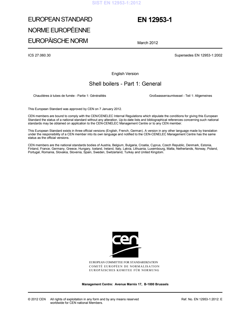
EUROPEAN STANDARD NORME EUROPÉENNE EUROPÄISCHE NORM
EN 12953-1
March 2012 ICS 27.060.30 Supersedes EN 12953-1:2002English Version
Shell boilers - Part 1: General
Chaudières à tubes de fumée - Partie 1: Généralités
Großwasserraumkessel - Teil 1: Allgemeines This European Standard was approved by CEN on 7 January 2012.
CEN members are bound to comply with the CEN/CENELEC Internal Regulations which stipulate the conditions for giving this European Standard the status of a national standard without any alteration. Up-to-date lists and bibliographical references concerning such national standards may be obtained on application to the CEN-CENELEC Management Centre or to any CEN member.
This European Standard exists in three official versions (English, French, German). A version in any other language made by translation under the responsibility of a CEN member into its own language and notified to the CEN-CENELEC Management Centre has the same status as the official versions.
CEN members are the national standards bodies of Austria, Belgium, Bulgaria, Croatia, Cyprus, Czech Republic, Denmark, Estonia, Finland, France, Germany, Greece, Hungary, Iceland, Ireland, Italy, Latvia, Lithuania, Luxembourg, Malta, Netherlands, Norway, Poland, Portugal, Romania, Slovakia, Slovenia, Spain, Sweden, Switzerland, Turkey and United Kingdom.
EUROPEAN COMMITTEE FOR STANDARDIZATION
COMITÉ EUROPÉEN DE NORMALISATION EUROPÄISCHES KOMITEE FÜR NORMUNG
Management Centre:
Avenue Marnix 17,
B-1000 Brussels © 2012 CEN All rights of exploitation in any form and by any means reserved worldwide for CEN national Members. Ref. No. EN 12953-1:2012: ESIST EN 12953-1:2012
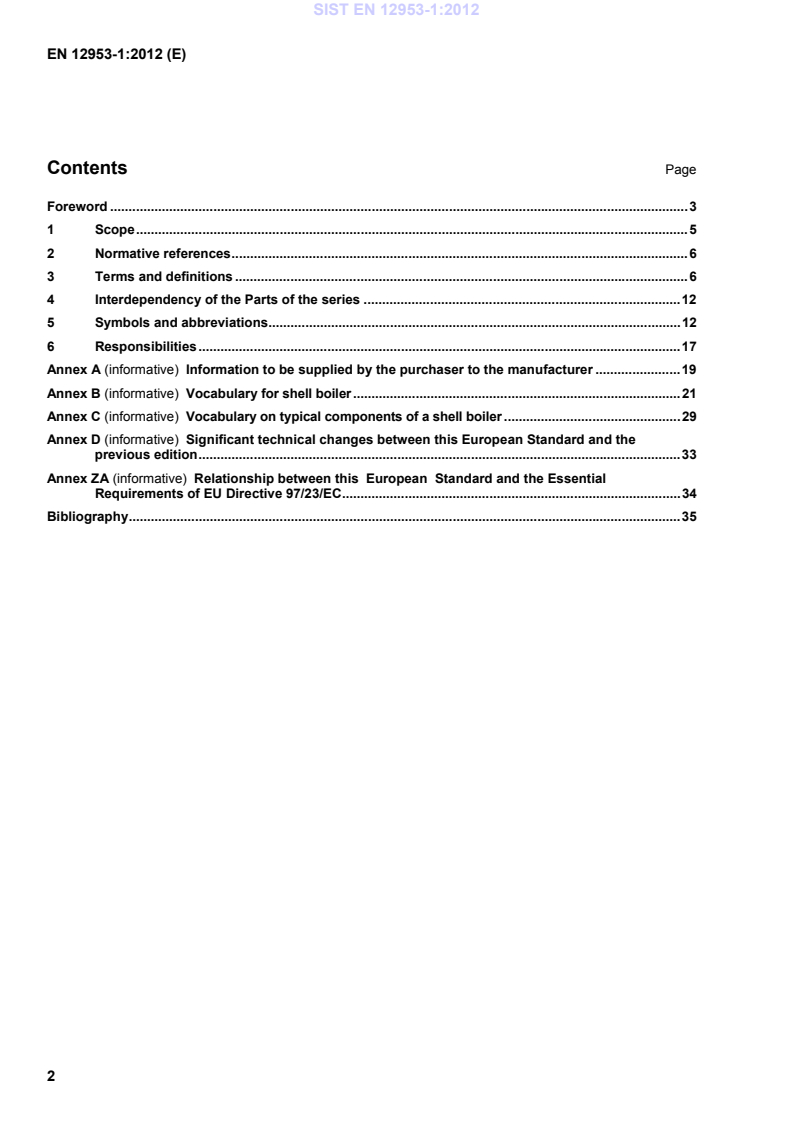
Information to be supplied by the purchaser to the manufacturer . 19Annex B (informative)
Vocabulary for shell boiler . 21Annex C (informative)
Vocabulary on typical components of a shell boiler . 29Annex D (informative)
Significant technical changes between this European Standard and the
previous edition . 33Annex ZA (informative)
Relationship between this
European
Standard and the Essential Requirements of EU Directive 97/23/EC . 34Bibliography . 35 SIST EN 12953-1:2012
110 °C. The purpose of this European Standard is to ensure that the hazards associated with the operation of shell boilers are reduced to a minimum and that adequate protection is provided to contain the hazards that still prevail when the shell boiler is put into service. This protection will be achieved by the proper application of the design, manufacturing, testing and inspection methods and techniques incorporated in the various parts of this European Standard. Where appropriate, adequate warning of residual hazards and the potential for misuse are given in the training and operating instructions and local to the equipment concerned (see EN 12953-7 and EN 12953-8). It is the manufacturer's responsibility, in addition to complying with the requirements of this standard, to take into consideration special measures which could be necessary in order to achieve by manufacturing the required level of safety in accordance with the EU Directive 97/23/EC (PED). NOTE 1 Further requirements relating to operating instructions in EN 12953-13 and to hazard analysis in
CEN/TS 764-6 should be taken into consideration. This European Standard specifies requirements for both directly fired and electrically heated boilers including Low Pressure Boilers (LPB, see 3.6) as well as for heat recovery boilers with a gas-side pressure not exceeding 0,5 bar of cylindrical design, constructed from carbon or carbon manganese steels by fusion welding and a design pressure not exceeding 40 bar. The boilers covered by this European Standard are intended for land use for providing steam or hot water (typical examples are shown in Figures 1 to 6). For Low Pressure Boilers (LPB) less stringent requirements concerning design and calculation are acceptable. Details are defined in the respective clauses. NOTE 2 For boilers operating at a pressure on the gas-side greater than 0,5 bar the rules of this standard equally apply. However, it is generally considered that additional design analysis, inspection and testing may be necessary. Where a particular boiler is a combination of shell and water-tube design then the water-tube standard series EN 12952 is used in addition to this European Standard. One such example of this combination is shown in Figure 3. This European Standard applies to the generator, from the feed-water or water inlet connection to the steam or water outlet connection and to all other connections, including the valves and steam and water fittings. If welded ends are used, the requirements specified herein begin or end at the weld where flanges, if used, would have been fitted. 1.2 Exclusions This European standard does not apply to the following types of boilers and equipments: a) water-tube boilers; b) non stationary boilers, e.g. locomotive boilers; c) thermal oil boilers; d) boilers where the main pressure housing is made of cast material. e) pumps, gaskets, etc. SIST EN 12953-1:2012
individual or organization that buys the boiler or part thereof from the manufacturer
3.2
manufacturer individual or organisation that is responsible for the design, fabrication, testing, inspection, installation of pressure equipment and assemblies where relevant
[SOURCE: EN 764-3:2002] Note 1 to entry: The manufacturer can subcontract one or more of the above mentioned tasks under its responsibility (for example, designer, installer, etc.).
3.3 material supplier
individual or organisation, that may or may not be the material manufacturer, who supplies material or parts used in the manufacture of pressure equipment and assemblies [SOURCE: EN 764-3:2002] Note 1 to entry: A material supplier may be a stockist. 3.4
material manufacturer
individual or organisation that produces material in the basic product forms used in the manufacture of pressure equipment
[SOURCE: EN 764-3:2002] SIST EN 12953-1:2012
Note 1 to entry: Depending on the contractual circumstances, the installer may be considered as the manufacturer of the assembly. 3.6
low pressure boilers (LPB)
steam boilers with a maximum saturation temperature of 120 °C (this corresponds to a pressure of 1 bar gauge) or hot water boilers with a maximum outlet temperature of 120 °C and a maximum allowable pressure of 10 bar gauge Note 1 to entry: The manufacturer may have the option of using this harmonised European Standard or alternatively EN 14394 for low pressure boilers which are to be used as hot water heating boilers. 3.7 shell boiler closed vessel containing water in which flames and/or hot gases pass through the inside of tubes located within the shell which forms part of an assembly
Note 1 to entry: This is opposed to water-tube boiler where the water is inside the tubes and flue gas is outside the tubes.
Note 2 to entry: Figures 1 to 6 are typical configurations and examples of shell boilers. Other configurations are also permissible (e.g. vertical shell). Note 3 to entry: Informative Annex C gives translations of some typical components of a shell boiler.
Key 1) cylindrical shell 2) furnace tube (1st pass): for example plain or corrugated or with bowling hoops 3) front tube plate (or front plate depending on the configuration) 4) rear plate (or rear tube plate depending on the configuration) 5) smoke tube(s) (2nd pass/3rd pass) (maybe with stay tubes or bar stays) 6) wrapper plate (shell of reversal chamber) 7) reversal chamber tube plate 8) wet back rear plate 12) lifting lugs 13) gusset stays 14) branches 15) supports 16) inspection opening
NOTE The main pressure-bearing parts are the parts, which constitute the envelope under pressure, and the parts which are essential for the integrity of the boiler. Figure 1 — Typical components of a shell boiler
a) two pass boiler b) three pass boiler Key 1) cylindrical shell 2) furnace tube (1st pass): for example plain or corrugated or with bowling hoops 3) front tube plate (or front plate depending on the configuration) 4) rear plate (or rear tube plate depending on the configuration) 5) smoke tube(s) (2nd pass/3rd pass) (maybe with stay tubes or bar stays) 6) wrapper plate (shell of reversal chamber) 7) reversal chamber tube plate 8) wet back rear plate NOTE The effective radiant heating surface comprises the furnace tube and the surface of the reversal chamber, where applicable. Figure 2 — Wet back boiler with internal reversal chamber
a) two pass boiler b) three pass boiler Key 1) cylindrical shell 2) furnace tube (1st pass): for example plain or corrugated or with bowling hoops 3) front tube plate (or front plate depending on the configuration) 4) rear plate (or rear tube plate depending on the configuration) 5) smoke tube(s) (2nd pass/3rd pass) (maybe with stay tubes or bar stays) 9)
header 10)
membrane wall
NOTE The effective radiant heating surface comprises the furnace tube and complete surface of the reversal chamber. Figure 3 — Wet back boiler with external reversal chamber
a) two pass boiler b) three pass boiler Key 1) cylindrical shell 2) furnace tube (1st pass): for example plain or corrugated or with bowling hoops 3) front tube plate (or front plate depending on the configuration) 4) rear plate (or rear tube plate depending on the configuration) 5) smoke tube(s) (2nd pass/3rd pass) (maybe with stay tubes or bar stays) 6) wrapper plate (shell of reversal chamber)
7)
reversal chamber tube plate
11)
insulation: for example refractory NOTE The effective radiant heating surface comprises the furnace tube wrapper plate and reversal chamber tube plate. Figure 4 — Semi-wet back boiler
a) two pass boiler b) three pass boiler Key 1) cylindrical shell 2) furnace tube (1st pass): for example plain or corrugated or with bowling hoops 3) front tube plate (or front plate depending on the configuration) 4) rear plate (or rear tube plate depending on the configuration) 5) smoke tube(s) (2nd pass/3rd pass) (maybe with stay tubes or bars)
11)
insulation: for example refractory NOTE The effective radiant heating surface comprises the furnace tube and rear tube plate. Figure 5 — Dry back boiler SIST EN 12953-1:2012
Key 1) cylindrical shell 2) furnace tube (1st pass): for example plain or corrugated or with bowling hoops 3) front tube plate (or front plate depending on the configuration) 4) rear plate (or rear tube plate depending on the configuration)
5)
smoke tube(s) (2nd pass/3rd pass) (maybe with stay tubes or bars) NOTE The effective radiant heating surface consists of the furnace only. Figure 6 — Reverse flame boiler
3.8 generator assembly with boiler, burner, valves and, if applicable, protective devices Note 1 to entry: For this European Standard, the term “generator” is applicable to shell boilers (see Figure B.2). 3.9 assembly consists, as a minimum a generator, and where applicable, with an economiser and/or a superheater,
inter-connecting piping and instrumentation (protective, control and indicating devices) placed on the market by one manufacturer
Note 1 to entry: See also Figure B.3. 3.10 operating instructions see EN 12953-13
For the purposes of this European Standard, the general symbols and abbreviations indicated in Table 1 shall apply, however specific symbols and abbreviations can be used for specific requirements in other Parts of the standard. Table 1 — Symbols and abbreviations — (1 of 6) Symbol Description Unit A Effective radiant heating surface (see Figures 1 to 6) m2 Af Cross-sectional area effective as compensation without consideration of allowances mm2 Afb Cross-sectional area of branch effective as compensation mm2 Afp Cross-sectional area of reinforcing pad effective as compensation mm2 Afs Cross-sectional area of main body effective as compensation mm2 Ap Pressure-loaded area without consideration of allowances mm2 Apb Pressure-loaded area relative to branch mm2 Aps Pressure-loaded area relative to main body mm2 At Original cross-sectional area of test piece subjected to a tensile test mm2 a Dimensions indicated in EN 12953-3, Figures 10.1-1, 10.2-2 to 10.2-4 mm ai Inner major axis of compensation plate mm ao Outer major axis of compensating plate mm b Dimensions indicated as examples in EN 12953-3, Figures 10.1-1, 10.2-2 to 10.2-5, 13.1-1 and in EN 12953-3, Annex B mm b1 Minor axis of manhole mm bi Inner minor axis of compensating plate mm bo Outer minor axis of compensating plate mm C Shape factor for unstayed dished heads without openings indicated in EN 12953-3, Figure 9.1-1 — C1 Shape factor for unstayed walls, ends or plates as given in EN 12953-3, 9.2 — SIST EN 12953-1:2012
mm dop Diameter of outer periphery of circular pad of compensating plate mm dos Nominal outside diameter of main body
mm ds Diameter of stay mm E Modulus of elasticity at design temperature MPa
e Wall thickness mm ecb Calculated wall thickness of branch or nozzle without allowances mm ecf Calculated wall thickness of furnace without allowances mm SIST EN 12953-1:2012
Description Unit ech Calculated wall thickness of flat end without allowances mm ecp Calculated wall thickness of reinforcing pad mm ecs Calculated wall thickness of the main body (cylindrical or spherical shells or dished ends) without allowances mm ect Calculated wall thickness of straight tube without allowances mm efa Calculated wall thickness of furnace with allowances mm eg Calculated thickness of gusset stay mm eh Ordered thickness of flat end mm eh1 Wall thickness in relief groove mm ep Ordered wall thickness of reinforcing pad mm erb Actual wall thickness of branch or nozzle without allowances mm erf Actual wall thickness of furnaces mm erh Actual wall thickness of flat end without allowances mm erp Actual wall thickness of reinforcing pad without allowances mm ers Actual wall thickness of main body (cylindrical or spherical shell or dished end) without allowances mm ert Actual tube wall thickness without allowances mm es Ordered wall thickness of main body mm esa Required wall thickness of main body with allowances mm et Ordered tube wall thickness mm eta Required wall thickness of straight tube with allowances mm F Calculation overall exchange factor — f Nominal design stress MPa fa Existing mean stress MPa
fa- Existing mean stress between the centres of two openings MPa fb Nominal design stress for branch material MPa fc Combined stress at supports MPa
fp Nominal design stress for reinforcing ring material MPa fs Nominal design stress for main body material MPa G Gas mass flow rate in first pass tubes kg/(m2 ⋅ s) SIST EN 12953-1:201
...