

kSIST FprEN IEC 60953-4:2026
(Main)Rules for steam turbine thermal acceptance tests - Part 4: Routine testing
- Status
- Not Published
- Public Enquiry End Date
- 31-Oct-2025
- Technical Committee
- I10 - Imaginarni 10 za neaktivna TDT na elektro področju
- Current Stage
- 5020 - Formal vote (FV) (Adopted Project)
- Start Date
- 02-Jun-2026
- Due Date
- 21-Jul-2026
- Completion Date
- 09-Jun-2026

kSIST FprEN IEC 60953-4:2026 is a SIST standard for routine testing of steam turbines. It specifies how to plan, measure, evaluate and compare routine thermal tests on existing steam turbines, so plant teams can monitor relative performance, cycle condition and maintenance needs over time.
What does kSIST FprEN IEC 60953-4:2026 specify?
kSIST FprEN IEC 60953-4:2026 is a supplementary standard for routine testing of steam turbines. It applies to steam turbines of every type, rating and application, operating with superheated or saturated steam, and it is aimed at existing plant equipment rather than acceptance tests for new units or retrofit work.
The document is organized into Clauses 1 to 8, followed by Annexes A to K. Clause 1 states the scope and object, Clause 2 lists the normative references, Clause 3 gives units, symbols, terms and definitions, Clause 4 covers guiding principles, Clause 5 covers measuring techniques and instruments, Clause 6 covers evaluation of tests, Clause 7 covers correction and comparison of results, and Clause 8 covers measuring uncertainty.
| Annex | What it covers |
|---|---|
| Annex A | Feedwater heater leakage and condenser leakage tests |
| Annex B | Evaluation of multiple measurements and compatibility |
| Annex C | Mass flow balances |
| Annex D | Short-statistical definition of measuring uncertainty and error propagation in acceptance test |
| Annex E | Temperature variation method |
| Annex F | Guidance on selecting the type of routine test to perform |
| Annex G | Sensitivity factors for component performance on overall cycle performance |
| Annex H | Typical thermodynamic boundary and instrument layout for routine tests |
| Annex I | Calculation and analysis of test results, with a numerical example |
| Annex J | Numerical example of uncertainty calculation for periodic routine tests |
| Annex K | Typical reasons for deviations of steam turbine performance from reference or design level |
What are the key requirements of kSIST FprEN IEC 60953-4:2026?
kSIST FprEN IEC 60953-4:2026 focuses on relative performance and repeatability. In practice, the document is about spotting deterioration, diagnosing where it occurs, and tracking trends over time, rather than proving an absolute acceptance value for a new machine.
Planning and test boundary
Clause 4 requires the parties to agree the test type, the measuring points, the instruments, the valve arrangement and the piping arrangement before testing. The same procedure should then be kept for later comparative tests, because consistency is what makes changes in performance meaningful.
Clause 4 also recommends regular scheduling, with routine tests carried out at least once a year and before and after overhaul when relevant. A single responsible leader should coordinate the test, assign tasks, control the start and end of the test, and handle abnormal situations. That matters because routine testing depends on disciplined execution, not just measurements.
Plant condition, isolation and leakage control
Before a test, the steam turbine, driven machine, condenser and feedheaters in scope should be in suitable condition, and leaks in condensers, feedheaters, pipes and valves should be eliminated as far as practicable. The cycle should be isolated so that flows outside the intended boundary are shut down or accounted for.
Clause 6.2.3.4 places special weight on leakage. If the unaccounted leakage difference between the current test and the reference test exceeds 0.2% of full-load main steam flow, it should be investigated and, if needed, corrected or compensated for. In practical terms, leakage can hide a real performance change, so it has to be checked before the test result is trusted.
Measuring techniques and instrument use
Clause 5 keeps accuracy important, but it gives priority to test repeatability and economical instrumentation. Permanently installed plant instruments may be used, especially for secondary parameters and for preliminary assessment, provided their calibration status is known. Temporary instruments should be calibrated as scheduled, usually once a year, and permanently installed instruments should be field-verified before the test.
For comparative testing, using the same instruments for the reference and current tests is preferred because it reduces uncertainty in the performance difference. Clause 5.4.6 sets calibration accuracy expectations for pressure measuring devices, with tighter accuracy for primary measurements than for less important ones. Clause 5.1.7 also notes that, for differential pressure flow devices in plant systems, flow may be recalculated in accordance with ISO 5167.
Flow, pressure and temperature measurements
Clause 5 identifies primary flows as flows directly related to power output, such as feedwater flow. Steam flow between the steam generator outlet and the turbine throttle may be used as an alternative in specific cases, but only when conditions support good repeatability and the steam is sufficiently superheated.
For steam flow measurement by the alternative method, the document says not to attempt it if superheat is less than 15 K at the smallest nozzle or orifice section. Pressure measurements are static measurements taken as close as practicable to the relevant turbine locations, and temperature measurements on the feed train are used to support diagnosis and validation. That means the test layout has to suit the plant, not just the calculation.
Routine test results and correction to reference conditions
Clause 3 identifies the main routine test results as thermal efficiency or Heat rate, power output, steam rate, main steam flow capacity, Thermal Load Capacity for Nuclear applications, and several component performance indicators. The standard therefore supports both whole-cycle review and component trending.
Clause 7 says routine test results should be corrected to reference conditions and compared with reference values, not guarantee values. The standard also emphasizes that correction methods must stay consistent with the reference test. For performance trending, thermal efficiency or heat rate versus power output, first-stage pressure, extraction pressure and other normalized parameters may be plotted over time to show deterioration.
Heat rate diagnosis and uncertainty
Clause 7.8.6.2 separates heat rate deviation into accountable and unaccountable parts. It points to terminal conditions, HP/IP turbine efficiency, feedwater heater performance, gland leakage, spray flows and cycle imperfections as sources to examine. In practice, this helps teams decide whether a change is due to the turbine, the cycle, or the test setup.
Clause 8 covers measuring uncertainty, and routine testing uncertainty is determined using the method from Annex F of IEC 60953-3:2023. Annex J then gives a numerical example for periodic routine tests. This matters because routine testing is judged mainly by the uncertainty of the performance difference between tests.
What terms does kSIST FprEN IEC 60953-4:2026 define?
Reference condition - The external parameters outside the test boundary to which the test results are corrected.
Reference test - A test carried out under reference condition and used as the baseline for comparison and diagnosis.
Comparative test - A current test, or series of tests, used to show relative performance change against the reference test.
Repeatability - The ability of the measurement system to give the same output/input relationship over extended time periods.
Primary parameters - Measured variables that significantly affect the test result and therefore need known calibration status.
Secondary parameters - Measured variables that have only a minor effect on the test result.
Terminal Temperature Difference (TTD) - The difference between the saturation temperature at the steam inlet pressure and the feedwater heater outlet temperature.
Drain Cooler Approach (DCA) - The difference between the drain outlet temperature and the feedwater heater inlet temperature.
Who uses kSIST FprEN IEC 60953-4:2026?
kSIST FprEN IEC 60953-4:2026 is used by people who run, test and maintain steam turbine plants. The document names performance engineers, operators and maintenance staff as part of the test team, and its methods fit routine monitoring, outage planning, diagnosis and long-term trend analysis.
It is relevant across steam turbine applications, including large condensing plants, back-pressure turbines, extraction turbines and nuclear applications where Thermal Load Capacity is considered. It is also useful when a plant needs to compare current operation with a reference test after overhaul, modification or a long period of service.
Which standards are used with kSIST FprEN IEC 60953-4:2026?
IEC 60953-0:2022 is the base document for this part. kSIST FprEN IEC 60953-4:2026 is meant to be read with it, and it provides the common rules, definitions and most of the measurement and evaluation methods that this part supplements.
IEC 60953-3:2023 contributes the method used for routine testing uncertainty of performance differences. Clause 8.5.6 points to Annex F of IEC 60953-3:2023 for that calculation.
ISO 5167 is cited for recalculating flow when differential pressure devices are used in plant instrumentation. It matters where existing plant data systems or parallel test transmitters are used for flow measurement.
What does the kSIST FprEN IEC 60953-4:2026 document contain?
The document contains guidance on selecting a suitable routine test type, including routine monitoring and periodic performance tests. Annex F links test choice to the question being asked, such as output monitoring, flow capacity monitoring, heat rate testing or cylinder efficiency testing.
It also contains worked methods, figures and layouts for practical testing. Figures 2 and 3 show typical instrumentation arrangements for periodic thermal efficiency tests, Annex H shows typical thermodynamic boundaries and instrument layouts, and Annex I gives a numerical calculation and analysis example.
For diagnosis and interpretation, Annex G gives sensitivity tables for component performance, while Annex K lists typical reasons for deviations from reference or design level. Annex A, Annex B and Annex C support leakage tests, multiple measurement evaluation and mass flow balances, which are the parts most often needed when a routine test result has to be defended or explained.
Get Certified
Connect with accredited certification bodies for this standard

DNV
DNV is an independent assurance and risk management provider.

Lloyd's Register
Lloyd's Register is a global professional services organisation specialising in engineering and technology.
DNV Energy Systems
Energy and renewable energy certification.
Sponsored listings
Frequently Asked Questions
kSIST FprEN IEC 60953-4:2026 is a draft published by the Slovenian Institute for Standardization (SIST). Its full title is "Rules for steam turbine thermal acceptance tests - Part 4: Routine testing". This standard covers: Rules for steam turbine thermal acceptance tests - Part 4: Routine testing
Rules for steam turbine thermal acceptance tests - Part 4: Routine testing
kSIST FprEN IEC 60953-4:2026 is classified under the following ICS (International Classification for Standards) categories: 27.040 - Gas and steam turbines. Steam engines. The ICS classification helps identify the subject area and facilitates finding related standards.
kSIST FprEN IEC 60953-4:2026 is available in PDF format for immediate download after purchase. The document can be added to your cart and obtained through the secure checkout process. Digital delivery ensures instant access to the complete standard document.
Standards Content (Sample)
SLOVENSKI STANDARD
oSIST prEN IEC 60953-4:2025
01-oktober-2025
Pravila za preskuse toplotne sprejemljivosti parne turbine - 4. del: Rutinsko
preskušanje
Rules for steam turbine thermal acceptance tests - Part 4: Routine testing
Ta slovenski standard je istoveten z: prEN IEC 60953-4:2025
ICS:
27.040 Plinske in parne turbine. Gas and steam turbines.
Parni stroji Steam engines
oSIST prEN IEC 60953-4:2025 en
2003-01.Slovenski inštitut za standardizacijo. Razmnoževanje celote ali delov tega standarda ni dovoljeno.
oSIST prEN IEC 60953-4:2025
oSIST prEN IEC 60953-4:2025
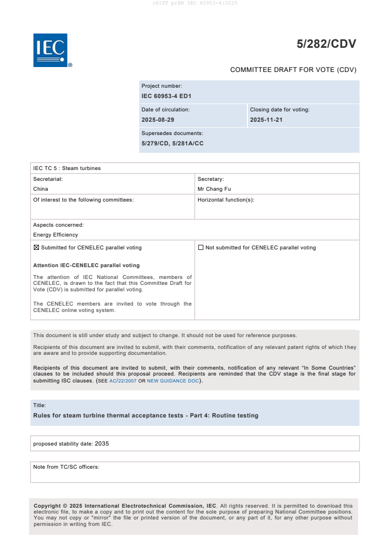
5/282/CDV
COMMITTEE DRAFT FOR VOTE (CDV)
Project number:
IEC 60953-4 ED1
Date of circulation: Closing date for voting:
2025-08-29 2025-11-21
Supersedes documents:
5/279/CD, 5/281A/CC
IEC TC 5 : Steam turbines
Secretariat: Secretary:
China Mr Chang Fu
Of interest to the following committees: Horizontal function(s):
Aspects concerned:
Energy Efficiency
Submitted for CENELEC parallel voting Not submitted for CENELEC parallel voting
Attention IEC-CENELEC parallel voting
The attention of IEC National Committees, members of
CENELEC, is drawn to the fact that this Committee Draft for
Vote (CDV) is submitted for parallel voting.
The CENELEC members are invited to vote through the
CENELEC online voting system.
This document is still under study and subject to change. It should not be used for reference purposes.
Recipients of this document are invited to submit, with their comments, notification of any relevant patent rights of which t hey
are aware and to provide supporting documentation.
Recipients of this document are invited to submit, with their comments, notification of any relevant “In Some Countries”
clauses to be included should this proposal proceed. Recipients are reminded that the CDV stage is the final stage for
submitting ISC clauses. (SEE AC/22/2007 OR NEW GUIDANCE DOC).
Title:
Rules for steam turbine thermal acceptance tests - Part 4: Routine testing
proposed stability date: 2035
Note from TC/SC officers:
electronic file, to make a copy and to print out the content for the sole purpose of preparing National Committee positions.
You may not copy or "mirror" the file or printed version of the document, or any part of it, for any other purpose without
permission in writing from IEC.
oSIST prEN IEC 60953-4:2025
IEC CDV 60953-4 ED1 © IEC 2025
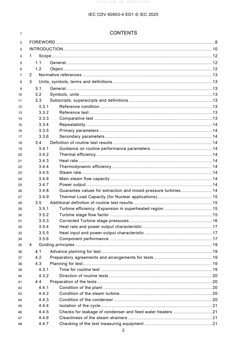
1 CONTENTS
2 FOREWORD . 8
3 INTRODUCTION . 10
4 1 Scope . 12
5 1.1 General . 12
6 1.2 Object . 12
7 2 Normative references . 13
8 3 Units, symbols, terms and definitions . 13
9 3.1 General . 13
10 3.2 Symbols, units . 13
11 3.3 Subscripts, superscripts and definitions . 13
12 3.3.1 Reference condition . 13
13 3.3.2 Reference test . 13
14 3.3.3 Comparative test . 13
15 3.3.4 Repeatability . 14
16 3.3.5 Primary parameters . 14
17 3.3.6 Secondary parameters . 14
18 3.4 Definition of routine test results . 14
19 3.4.1 Guidance on routine performance parameters . 14
20 3.4.2 Thermal efficiency . 14
21 3.4.3 Heat rate . 14
22 3.4.4 Thermodynamic efficiency . 14
23 3.4.5 Steam rate . 14
24 3.4.6 Main steam flow capacity . 14
25 3.4.7 Power output . 14
26 3.4.8 Guarantee values for extraction and mixed-pressure turbines . 14
27 3.4.9 Thermal Load Capacity (for Nuclear applications) . 15
28 3.5 Additional definition of routine test results . 15
29 3.5.1 Turbine efficiency -Expansion in superheated region . 15
30 3.5.2 Turbine stage flow factor . 15
31 3.5.3 Corrected Turbine stage pressures . 16
32 3.5.4 Heat rate and power output characteristic . 17
33 3.5.5 Heat input and power output characteristic . 17
34 3.5.6 Component performance . 17
35 4 Guiding principles . 19
36 4.1 Advance planning for test. 19
37 4.2 Preparatory agreements and arrangements for tests . 19
38 4.3 Planning for test. 19
39 4.3.1 Time for routine test . 19
40 4.3.2 Direction of routine tests . 20
41 4.4 Preparation of the tests . 20
42 4.4.1 Condition of the plant . 20
43 4.4.2 Condition of the steam turbine . 20
44 4.4.3 Condition of the condenser . 20
45 4.4.4 Isolation of the cycle . 21
46 4.4.5 Checks for leakage of condenser and feed water heaters . 21
47 4.4.6 Cleanliness of the steam strainers . 21
48 4.4.7 Checking of the test measuring equipment . 21
oSIST prEN IEC 60953-4:2025
IEC CDV 60953-4 ED1 © IEC 2025
49 4.5 Comparison measurements . 21
50 4.6 Settings for tests . 22
51 4.6.1 Load settings . 22
52 4.6.2 Special settings . 22
53 4.7 Preliminary tests . 22
54 4.8 Acceptance tests . 22
55 4.8.1 Constancy of test conditions . 22
56 4.8.2 Maximum deviation and fluctuation in test conditions . 22
57 4.8.3 Duration of test runs and frequency of reading. 22
58 4.8.4 Reading of integrating measuring instruments . 22
59 4.8.5 Alternative methods . 22
60 4.8.6 Recording of tests . 22
61 4.8.7 Additional measurement . 22
62 4.8.8 Preliminary calculations . 22
63 4.8.9 Consistency and number of tests . 22
64 4.9 Repetition of Acceptance tests . 23
65 5 Measuring techniques and measuring instruments . 23
66 5.1 Overview . 23
67 5.1.1 Instrument accuracy requirements . 23
68 5.1.2 Measuring instruments . 23
69 5.1.3 Measuring uncertainty . 23
70 5.1.4 Calibration of instruments . 23
71 5.1.5 Alternative instrumentation . 23
72 5.1.6 Consistency of comparative test instruments . 23
73 5.1.7 Special considerations of permanently installed instrument . 24
74 5.2 Measurement of power. 25
75 5.2.1 Determination of mechanical turbine output . 25
76 5.2.2 Measurement of boiler feed pump power . 25
77 5.2.3 Determination of electrical power of a turbine generator . 25
78 5.2.4 Measurement of electrical power . 25
79 5.2.5 Electrical instrument connections. 25
80 5.2.6 Electrical instruments . 25
81 5.2.7 Instrument transformers . 25
82 5.3 Flow measurement . 25
83 5.3.1 Determination of flows to be measured . 25
84 5.3.2 Measurement of primary flow . 29
85 5.3.3 Installation and location of flow measuring devices . 29
86 5.3.4 Calibration of primary flow devices for water flow . 29
87 5.3.5 Inspection of flow measuring devices . 30
88 5.3.6 Differential pressure measurements . 30
89 5.3.7 Water flow fluctuation . 30
90 5.3.8 Secondary flow measurements . 30
91 5.3.9 Occasional secondary flows. 31
92 5.3.10 Density of water and steam . 31
93 5.3.11 Determination of cooling water flow of condenser . 31
94 5.4 Pressure measurement (excluding condensing turbine exhaust pressure) . 31
95 5.4.1 Pressures to be measured . 31
96 5.4.2 Instruments . 32
97 5.4.3 Main pressure measurements . 32
oSIST prEN IEC 60953-4:2025
IEC CDV 60953-4 ED1 © IEC 2025
98 5.4.4 Pressure tapping holes and connecting lines . 32
99 5.4.5 Shut-off valves . 32
100 5.4.6 Calibration of pressure measuring devices . 32
101 5.4.7 Atmospheric pressure . 33
102 5.4.8 Correction of readings . 33
103 5.5 Condensing turbine exhaust pressure measurement . 33
104 5.5.1 General . 33
105 5.5.2 Plane of measurement . 33
106 5.5.3 Pressure taps . 33
107 5.5.4 Manifolds . 33
108 5.5.5 Connecting lines . 33
109 5.5.6 Instruments . 33
110 5.5.7 Calibration . 33
111 5.6 Temperature measurement . 34
112 5.6.1 Points of temperature measurement . 34
113 5.6.2 Instruments . 34
114 5.6.3 Main temperature measurements . 34
115 5.6.4 Feed train temperature measurements (including bled steam) . 34
116 5.6.5 Condenser cooling water temperature measurement . 34
117 5.6.6 Thermometer wells . 34
118 5.6.7 Precautions to be observed in the measurement of temperature . 34
119 5.7 Steam quality determination . 35
120 5.7.1 General . 35
121 5.7.2 Tracer technique . 35
122 5.7.3 Condensing method . 35
123 5.7.4 Constant rate injection method . 35
124 5.7.5 Extraction enthalpy determined by constant rate injection method . 35
125 5.7.6 Tracers and their use . 35
126 5.8 Time measurement . 35
127 5.9 Speed measurement . 36
128 6 Evaluation of tests . 36
129 6.1 Preparation of evaluation . 36
130 6.2 Computation of results . 36
131 6.2.1 Calculation of average values of instrument readings . 36
132 6.2.2 Correction and conversion of averaged readings . 36
133 6.2.3 Checking of measured data . 36
134 6.2.4 Thermodynamic properties of steam and water . 37
135 6.2.5 Calculation of test results . 37
136 7 Correction of test results and comparison with guarantee . 37
137 7.1 Guarantee values and guarantee conditions . 37
138 7.2 Correction of initial steam flow capacity . 37
139 7.3 Correction of output . 37
140 7.3.1 Correction of maximum output . 37
141 7.3.2 Correction of Output with specified initial steam flow . 37
142 7.4 Correction of the thermal performance . 37
143 7.5 Definition and application of correction values . 38
144 7.6 Correction methods . 38
145 7.6.1 General . 38
146 7.6.2 Correction by heat balance calculation . 38
oSIST prEN IEC 60953-4:2025
IEC CDV 60953-4 ED1 © IEC 2025
147 7.6.3 Correction by use of correction curves prepared by the manufacturer . 38
148 7.6.4 Tests to determine correction values . 38
149 7.7 Variables to be considered in the correction of specific turbine cycles . 38
150 7.7.1 Scope of corrections . 38
151 7.7.2 Turbines with regenerative feed-water heating . 38
152 7.7.3 Turbines which have no provision for the addition or extraction of steam
153 after partial expansion . 39
154 7.7.4 Turbines with steam extraction for purposes other than feed-water
155 heating (extraction turbines) . 40
156 7.7.5 Other types of turbine . 40
157 7.8 Guarantee comparison . 40
158 7.8.1 Tolerance and weighting . 40
159 7.8.2 Guarantee comparison with locus curve . 40
160 7.8.3 Guarantee comparison with guarantee point . 40
161 7.8.4 Guarantee comparison for turbines with throttle governing . 40
162 7.8.5 Guarantee comparison for extraction turbines . 40
163 7.8.6 Additional consideration for routine test results comparison . 40
164 7.9 Deterioration of turbine performance (ageing) . 42
165 7.9.1 Timing to minimise deterioration . 42
166 7.9.2 Correction with comparison tests . 42
167 7.9.3 Correction without comparison tests . 42
168 8 Measuring uncertainty . 42
169 8.1 General . 42
170 8.2 Determination of measuring uncertainty of steam and water properties . 42
171 8.2.1 Pressure . 42
172 8.2.2 Temperature . 42
173 8.2.3 Enthalpy and enthalpy difference . 42
174 8.3 Calculation of measuring uncertainty of output . 42
175 8.3.1 Electrical measurement . 42
176 8.3.2 Mechanical measurement . 43
177 8.3.3 Additional uncertainty allowance because of unsteady load conditions . 43
178 8.4 Determination of measuring uncertainty of mass flow . 43
179 8.4.1 Measuring uncertainty of mass flow measurements . 43
180 8.4.2 Measuring uncertainty of multiple measurements of primary flow . 43
181 8.4.3 Uncertainty allowance for cycle imperfections . 43
182 8.5 Calculation of measuring uncertainty of results . 43
183 8.5.1 General . 43
184 8.5.2 Measuring uncertainty of thermal efficiency . 43
185 8.5.3 Measuring uncertainty of thermodynamic efficiency . 43
186 8.5.4 Uncertainty of corrections . 43
187 8.5.5 Guiding values for the measuring uncertainty of results . 43
188 8.5.6 Routine testing uncertainty . 43
189 8.6 Example uncertainty calculation . 43
190 Annex A (normative) Feedwater heater leakage and condenser leakage tests . 44
191 Annex B (normative) Evaluation of multiple measurements, compatibility . 45
192 Annex C (normative) Mass flow balances . 46
193 Annex D (informative) Short-statistical definition of measuring uncertainty and error
194 propagation in acceptance test . 47
195 Annex E (informative/normative) Temperature variation method . 48
oSIST prEN IEC 60953-4:2025
IEC CDV 60953-4 ED1 © IEC 2025
196 Annex F (informative) Guidance on selection a type of routine test to be performed . 49
197 F.1 Routine monitoring . 49
198 F.1.1 Components performance (cylinder, Heater, Deaerator, Condenser,
199 Pump& feed Turbine, system leakage) . 49
200 F.1.2 Output monitoring . 49
201 F.1.3 Flow capacity monitoring . 49
202 F.1.4 Pressure and temperature profiles . 50
203 F.2 Periodical performance tests . 50
204 F.2.1 Maximum power test . 50
205 F.2.2 Steam rate test . 50
206 F.2.3 Thermal efficiency test (Heat rate) . 50
207 F.2.4 Cylinder isentropic efficiency test(Enthalpy drop test) . 50
208 F.2.5 Measurement of heat input to cycle . 51
209 F.2.6 Measurement of heat rejected from cycle. 51
210 Annex G (informative) Sensitivity factors for some component performance on overall
211 cycle performance . 52
212 G.1 Large reheat fossil cycle . 52
213 G.2 Small industrial back pressure turbine with extraction . 52
214 G.3 Combined cycle condensing turbine with injection . 53
215 Annex H (informative) Typical thermodynamic boundary and instrument layout for
216 routine tests . 54
217 H.1 Typical thermodynamic boundary and instrument layouts . 54
218 Annex I (informative) Calculation and analysis of test results – numerical example . 57
219 I.1 General . 57
220 I.2 Instrumentation . 58
221 I.3 Measuring points layout . 61
222 I.4 Conduct of the test. 61
223 I.5 Calculation and Interpretation of test results . 62
224 I.5.1 Corrections and main test results for turbine . 62
225 I.5.2 Heat Rate Diagnosis . 64
226 I.5.3 Flow capacity and power output . 65
227 I.5.4 HP/IP cylinder efficiency . 65
228 I.5.5 HP Heaters performance . 66
229 I.5.6 System leakage status . 67
230 Annex J (informative) Numerical example of uncertainty calculation –periodic routine
231 tests . 68
232 J.1 General . 68
233 J.2 Measurement uncertainty . 68
234 J.3 Uncertainty calculation results . 68
235 Annex K (informative) Typical reasons for deviations of steam turbine performance
236 from reference or design level . 72
237 Bibliography . 74
239 Figure 1 – Isentropic efficiency of cylinder . 15
240 Figure 2 – Diagram showing location and type of test instrumentation for a typical
241 periodical thermal efficiency test . 27
242 Figure 3 – Diagram showing location and type of test instrumentation for a typical
243 periodical thermal efficiency test(final feedwater flow as primary flow) . 28
244 Figure H.1 – Example 1 . 54
oSIST prEN IEC 60953-4:2025
IEC CDV 60953-4 ED1 © IEC 2025
245 Figure H.2 – Example 2 . 55
246 Figure H.3 – Example 3 . 56
247 Figure H.4 – Example 3 . 56
248 Figure I.1 – Measuring points layout . 61
249 Figure I.2 – Corrected heat rate vs. power output relationship curve . 65
251 Table 1 – Apportionment of unaccounted leakages . 37
252 Table G.1 – Sensitivity of component performance on overall cycle performance for a
253 typical reheat fossil cycle . 52
254 Table G.2 – Sensitivity of components on overall cycle performance for a typical co-
255 generating unit . 52
256 Table G.3 – Sensitivity of components on overall cycle performance for a CCGT
257 turbine unit . 53
258 Table I.1 – Turbine technical specifications . 57
259 Table I.2 – Instrumentation list . 58
260 Table I.3 – Main test results of 350MW and VWO condition . 62
261 Table I.4 – Main test results of partial load conditions . 63
262 Table I.5 – Heat rate change due to boundary parameters (350MW, Post-outage test) . 64
263 Table I.6 – Heat rate change due to component performance (350MW, Post-outage
264 test) 64
265 Table I.7 – Heaters performance results . 66
266 Table J.1 – Assumed total measured variable uncertainty for pressure, temperature,
267 flow and generator output . 68
268 Table J.2 – The uncertainty result for Heat Rate difference of a fossil fired plant . 70
oSIST prEN IEC 60953-4:2025
IEC CDV 60953-4 ED1 © IEC 2025
270 INTERNATIONAL ELECTROTECHNICAL COMMISSION
271 ____________
273 RULES FOR STEAM TURBINE THERMAL ACCEPTANCE TESTS –
274 Part4: Routine testing
276 FOREWORD
277 1) The International Electrotechnical Commission (IEC) is a worldwide organization for standardization comprising
278 all national electrotechnical committees (IEC National Committees). The object of IEC is to promote
279 international co-operation on all questions concerning standardization in the electrical and electronic fields. To
280 this end and in addition to other activities, IEC publishes International Standards, Technical Specifications,
281 Technical Reports, Publicly Available Specifications (PAS) and Guides (hereafter referred to as “IEC
282 Publication(s)”). Their preparation is entrusted to technical committees; any IEC National Committee interested
283 in the subject dealt with may participate in this preparatory work. International, governmental and non -
284 governmental organizations liaising with the IEC also participate in this preparation. IEC collaborates closely
285 with the International Organization for Standardization (ISO) in accordance with conditions determined by
286 agreement between the two organizations.
287 2) The formal decisions or agreements of IEC on technical matters express, as nearly as possible, an international
288 consensus of opinion on the relevant subjects since each technical committee has representation from all
289 interested IEC National Committees.
290 3) IEC Publications have the form of recommendations for international use and are accepted by IEC National
291 Committees in that sense. While all reasonable efforts are made to ensure that the technical content of IEC
292 Publications is accurate, IEC cannot be held responsible for the way in which they are used or for any
293 misinterpretation by any end user.
294 4) In order to promote international uniformity, IEC National Committees undertake to apply IEC Publications
295 transparently to the maximum extent possible in their national and regional publications. Any divergence
296 between any IEC Publication and the corresponding national or regional publication shall be clearly indicated in
297 the latter.
298 5) IEC itself does not provide any attestation of conformity. Independent certification bodies provide conformity
299 assessment services and, in some areas, access to IEC marks of conformity. IEC is not responsible for any
300 services carried out by independent certification bodies.
301 6) All users should ensure that they have the latest edition of this publication.
302 7) No liability shall attach to IEC or its directors, employees, servants or agents including individual experts and
303 members of its technical committees and IEC National Committees for any personal injury, property damage or
304 other damage of any nature whatsoever, whether direct or indirect, or for costs (including legal fees) and
305 expenses arising out of the publication, use of, or reliance upon, this IEC Publication or any other IEC
306 Publications.
307 8) Attention is drawn to the Normative references cited in this publication. Use of the referenced publications is
308 indispensable for the correct application of this publication.
309 9) Attention is drawn to the possibility that some of the elements of this IEC Publication may be the subject of
310 patent rights. IEC shall not be held responsible for identifying any or all such patent rights.
311 IEC 60953-4 has been prepared by subcommittee WG11/PT60953-4: Thermal Acceptance Test, of IEC technical
312 committee 5: Steam Turbines.
313 The text of this International Standard is based on the following documents:
Draft Report on voting
5/XX/FDIS 5/XX/RVD
315 Full information on the voting for its approval can be found in the report on voting indicated in the above table.
316 The language used for the development of this International Standard is English.
317 A list of all parts in the IEC 60953 series, published under the general title Rules for steam turbine thermal
318 acceptance tests, can be found on the IEC website.
319 This document was drafted in accordance with ISO/IEC Directives, Part 2, and developed in accordance with
320 ISO/IEC Directives, Part 1 and ISO/IEC Directives, IEC Supplement, available at
321 www.iec.ch/members_experts/refdocs. The main document types developed by IEC are described in greater detail
322 at www.iec.ch/standardsdev/publications.
oSIST prEN IEC 60953-4:2025
IEC CDV 60953-4 ED1 © IEC 2025
323 The committee has decided that the contents of this document will remain unchanged until the stability date
324 indicated on the IEC website under webstore.iec.ch in the data related to the specific document. At this date, the
325 document will be
326 • reconfirmed,
327 • withdrawn,
328 • replaced by a revised edition, or
329 • amended.
oSIST prEN IEC 60953-4:2025
IEC CDV 60953-4 ED1 © IEC 2025
331 INTRODUCTION
332 Routine test in an existing power plant mainly involves an analysis, monitoring and
333 supervision of steam turbine performance. IEC 60953-0, which defines the rules for steam
334 turbine thermal acceptance tests in power plants, does not cater for all the requirements
335 specific to routine test. It was considered necessary to draw up a Supplementary Standard
336 (this document) for guidance on the routine tests of existing steam turbines.
337 However, a large number of the provisions and recommendations of IEC 60953 -0 are still
338 applicable to routine tests and, therefore, in order to avoid a repetitive and bulky document,
339 only the routine-specific addenda will be found in this document.
340 This part of IEC 60953-4 shall be read in conjunction with IEC 60953-0, and the words
341 ‘routine test’ should be read in place of ‘acceptance test’, the words‘ reference conditions’
342 should be read in place of ‘guarantee conditions’, the words ‘reference value’ should be read
343 in place of‘guarantee value’ as well.
344 Although this document is intended to apply to the routine test of large condensing steam
345 turbines, it can nevertheless be used for other types and sizes of turbines to define the basis
346 of a specific procedure to be agreed upon by the parties involved.
347 The purpose of this document is to cover the existing steam turbine components which
348 influence the efficiency of the power plant. This document helps the parties determine the
349 most appropriate parameters that characterise the relative performance change and that
350 could be used as long-term performance monitoring and analysis.
351 The accuracy of the routine test can approach that obtained while following IEC 60953-0, but
352 generally the simplified test results will yield less information about the plant and give less
353 assurance of accuracy. The relative performance rather than absolute value is emphasized in
354 this document. The repeatability of test result rather than test uncertainty is emphasized here
355 as well. In addition depending on the type of test and thermodynamic boundary chosen, the
356 full condition of each component might not be known. In some case, as per the result of
357 routine test, full or further diagnostic test maybe needed.
358 For reference purposes only, a numerical sample calculation and analysis of a fossil steam
359 turbine unit is presented in Annex I
360 The structure and clause numbering of this document follow that of IEC 60953-0. Subclauses
361 found in this document supersede the whole of the equivalent subclause in IEC 60953 -0.
362 Subclause numbering has been extended whenever new items have been included.
363 The main differences between this document and the IEC 60953-0 are listed below.
364 Clause 1: Scope
365 This document gives additional clauses for routine test of steam turbine, regarding the
366 analysis and supervision of relative performance by routine testing.
367 General principles and the determination of the measurement uncertainty of periodic routine
368 tests are given.
369 The purpose of this document is to provide simple and economic test procedures guider for
370 long-term and relative performance of the turbine and turbine cycles.
371 Specific simplified testing procedure is allowed, which results in less accuracy for absolute
372 values and wider uncertainty range. The accuracy for the results of performance changes is
373 sufficient for the purpose of the test.
oSIST prEN IEC 60953-4:2025
IEC CDV 60953-4 ED1 © IEC 2025
374 Clause 2: Normative references
375 IEC 60953-0 and IEC 60953-3 were added as reference.
376 Clause 3: Units symbols, terms and definitions
377 The definitions given in IEC 60953-0 applies to this document. Some new definitions involved
378 features of routine testing were added.
379 Clause 4: Guidance principles
380 The majority of the guiding principles contained in the IEC 60953-0 are also applicable to the
381 routine testing. This document gives further guidelines on the planning, timing, leadership of
382 the tests, the setting of the test and cycle isolation, and allowable test conditions.
383 Clause 4: Measuring techniques and measuring instruments
384 According to the purpose and scope of routine test, the specific requirements of the
385 consistency of the test instruments, the calibration of the instruments and the usage of
386 permanently installed instruments are given.
387 Clause 6: Evaluation of tests
388 This document gives further advice on allowable cycle leakages.
389 Clause 7: Correction of test results and comparison
390 Additional considerations for routine test results comparison including performance
391 parameters trending and heat rate diagnosis are given.
392 Clause 8: Measuring uncertainty
393 This clause of IEC 60953-0 is supplemented by provisions for special cases encountered in
394 routine testing in Annex J. The examples can be used as reference basis.
395 Annexes:
396 Annexes A to E of IEC 60953-0:20222022 applies.
397 Six new annexes were added to the existing ones.
398 Annex F Guidance on selection a type of routine test to be performed.
399 Annex G: Sensitivity factors for some component performance on overall cycle efficiency
400 Annex H: Typical thermodynamic boundary and instrument layout for routine tests
401 Annex I: Calculation and analysis of test results – numerical example
402 Annex J: Numerical examples of uncertainty calculation – periodic comparative test
403 Annex K: Typical reaso
...