

ISO 19123-2:2026
(Main)Geographic information — Schema for coverage geometry and functions — Part 2: Coverage implementation schema
- Abstract
This document specifies an implementable, conformance-testable coverage structure based on the abstract schema for coverages defined in the ISO 19123-1 coverage fundamentals. This document defines a concrete data structure that is suitable for encoding in many formats.
- Status
- Published
- Publication Date
- 15-Oct-2026
- Technical Committee
- ISO/TC 211 - Geographic information/Geomatics
- Drafting Committee
- ISO/TC 211/WG 6 - Imagery
- Current Stage
- 6060 - International Standard published
- Start Date
- 16-Oct-2026
- Completion Date
- 16-Oct-2026
ISO 19123-2:2026 is an ISO standard in the Geographic information series from ISO. It defines the Coverage implementation schema, a concrete, implementable and conformance-testable coverage structure based on ISO 19123-1 coverage fundamentals. It is written for people who need to encode, exchange, validate, or implement coverages in formats such as XML, JSON, and multipart representations.
What does ISO 19123-2:2026 specify?
ISO 19123-2:2026 specifies the logical and physical implementation of coverages, not the abstract coverage fundamentals themselves. It turns the ISO 19123-1 model into concrete data structures that can be encoded and tested.
The document is organized around coverage structure, coverage specializations, partitioning, and encodings:
| Annex | What it covers |
|---|---|
| Annex A | Abstract test suite for conformance |
| Annex B | Rectified and Referenceable Grid Coverages as normative legacy grid structures |
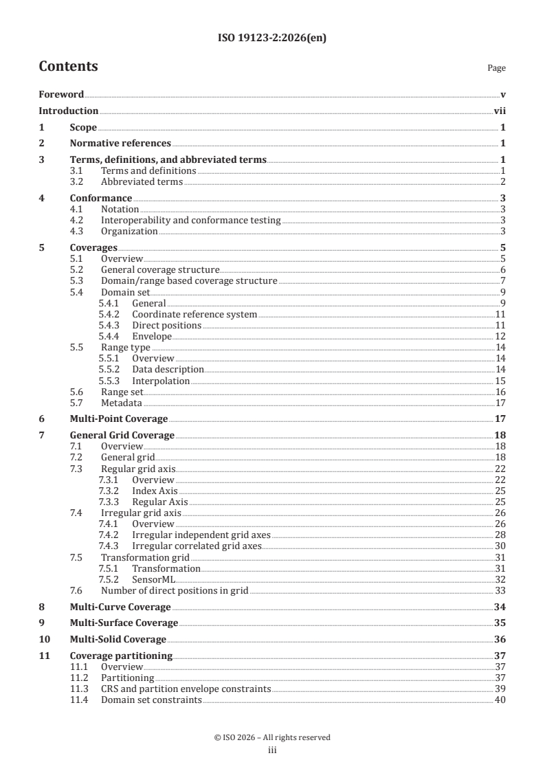
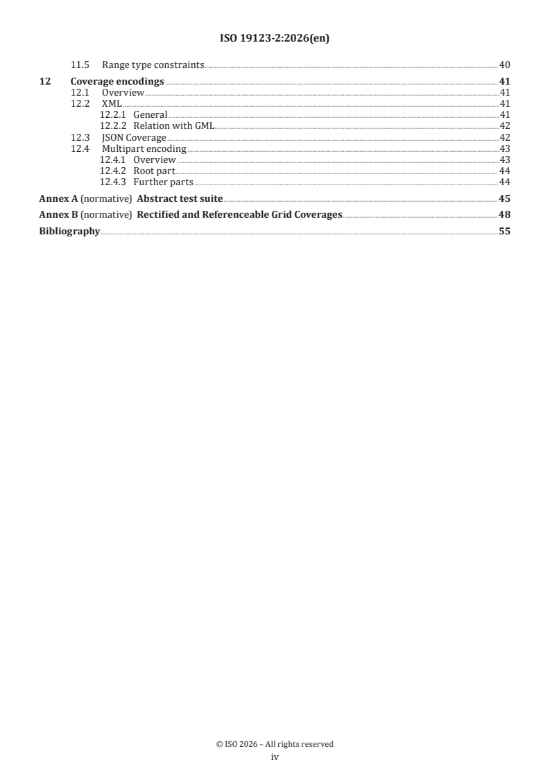
Clause 5 defines the common coverage structure. Clauses 6 to 10 define the main coverage types: Multi-Point Coverage, General Grid Coverage, Multi-Curve Coverage, Multi-Surface Coverage, and Multi-Solid Coverage. Clause 11 defines coverage partitioning, and Clause 12 defines XML, JSON Coverage, and Multipart encodings.
What are the key requirements of ISO 19123-2:2026?
ISO 19123-2:2026 requires an implementation to follow the Coverage Implementation Schema core, at least one coverage specialization, and at least one encoding, with conformance checked through Annex A. In practice, this means an implementer has to decide which coverage families and which serialization formats the system will support, then validate them against the standard’s test suite.
Core coverage structure
Clause 5 defines a coverage through four main components: domain set, range set, range type, and optional metadata. The domain set states where values are available, the range set holds the values, and the range type describes what those values mean. For implementers, this is the central model to store and exchange coverage data consistently.
Clause 5 also introduces coverageFunction for gridded coverages. The function describes how direct positions in a grid map to the linear order of values in the range set, using sequenceRule, axisOrder, and startPoint. In practice, this is what lets software read a multidimensional grid as an ordered array.
Required coverage classes
Clause 4 requires conformance to the abstract coverage class and at least one of the conformance classes grid-regular, grid-irregular, grid-transformation, pointcloud, or mesh, plus at least one of xml-coverage and json-coverage, and the Annex A tests. Clause 5 states that a coverage is one of MultiPointCoverage, GeneralGridCoverage, MultiCurveCoverage, MultiSurfaceCoverage, or MultiSolidCoverage.
That classification matters because it tells a system whether it is handling point clouds, raster-like grids, or curve-, surface-, or solid-based coverages. It also separates the common model from the storage and encoding choices.
Grid coverage rules
Clause 7 makes GeneralGridCoverage the unified grid model and requires exactly one range value for each direct position in the domain set. It also defines regular, irregular, and transformation grid axes, and it distinguishes grid dimension from CRS dimension. In practice, this supports mixed regular and irregular grids and makes grid handling more explicit for software.
For GeneralGridCoverage, the coverageFunction follows a linearization scheme, with Linear as the required value when the function is present. The axis order and start point determine how the multidimensional grid is traversed. This is important for interoperability because different software must read the same grid values in the same order.
Clause 7.6 provides the rule for the number of direct positions in a grid, based on the axis types and their extents or point lists. That rule is the basis for checking whether the range set size matches the grid domain size.
Point, curve, surface, and solid coverages
Clause 6 defines MultiPointCoverage as a domain set made of MultiPoint, and Clauses 8 to 10 define MultiCurveCoverage, MultiSurfaceCoverage, and MultiSolidCoverage with GML collections. These classes are useful when the coverage is built from discrete geometric elements rather than grid cells.
For these mesh-based coverages, the domain set is expressed with GML structures. In practice, this means implementers need to align their domain encoding with the GML collection type used by the chosen coverage class.
Partitioning and tiling
Clause 11 introduces CoverageByPartitioning, which allows a coverage to be built from sub-coverages or from direct position/value pairs. It supports partitioned, tiled, and interleaved representations, which is useful for large data sets and for storage layouts that split a coverage into smaller pieces.
Clause 11 also requires the partitioning structure to be acyclic, so a coverage cannot reference itself directly or indirectly. It further constrains sub-coverages to fit inside the super-coverage CRS and domain set, and it requires compatible range types, including null values where a range component or region is absent. In practice, this protects the consistency of mosaics, tiled datacubes, and band-partitioned data.
Encodings and conformance
Clause 12 defines XML, JSON Coverage, and Multipart encodings. The JSON coverage scheme must conform to IETF RFC 7159 and to the JSON Schema definitions in the standard, while the multipart scheme uses MIME multipart/related conventions.
Annex A links these rules to an abstract test suite. That gives implementers a clear route from schema design to testable conformance.
What terms does ISO 19123-2:2026 define?
ISO 19123-2:2026 defines the coverage terms it uses by reference to ISO 19123-1 and then adds a few implementation-specific terms.
- Coverage Implementation Schema (CIS) - the schema defined by this standard for concrete coverage structures and encodings.
- Coordinate Reference System (CRS) - the coordinate system in which the coordinates of a coverage domain are expressed.
- Regular grid - a grid whose direct positions have a constant distance along each axis.
- Irregular grid - a grid whose direct positions have individual distances along an axis.
- Displaced grid - a grid whose direct positions stay topologically aligned to a grid but can have arbitrary geometric positions.
- Partition - a separately stored coverage that acts as a component of another coverage through reference.
- Transformation grid - a grid whose direct positions are given by a transformation.
- Geography Markup Language (GML) - the markup language used for several domain-set and legacy grid structures.
- JavaScript Object Notation (JSON) - the encoding format used for the JSON Coverage conformance class.
Who uses ISO 19123-2:2026?
ISO 19123-2:2026 is used by software architects, geospatial developers, data platform teams, and standards implementers who need interoperable coverage models. It is relevant to remote sensing, raster and datacube storage, sensor-model-based geolocation, and services that expose coverage data.
Quality managers and procurement teams use it to check whether a product supports the needed coverage classes and encodings. Engineers use it to design schemas, validate conformance, and map data into XML, JSON, or multipart packages. It also matters to organizations working with WCS, WCPS, SensorML, and coverage partitioning or tiling.
What changed in ISO 19123-2:2026 from the previous edition?
ISO 19123-2:2026 cancels and replaces ISO 19123-2:2018 and is described as technically revised. The standard states these main changes:
- the structure is aligned with ISO 19123-1, with a clearer separation between logical UML structures and physical encodings
- terminology is aligned with ISO 19123-1
GeneralGridCoverageis added from OGC CIS 1.1 and extends grid modelling to irregular and mixed gridsRectifiedGridCoverageandReferenceableGridCoveragemove to normative Annex B as legacy coverage types- the UML schema is updated
- XML coverage encoding is complemented by a structurally equivalent JSON encoding
- the XML and JSON range-type schemas are copied from SWE Common to make the document more self-contained
- RDF encoding from OGC CIS 1.1 is not included
- the document adds clearer handling of interpolation methods,
EnvelopeByAxis, partitioned coverages, and more general grid identifiers
Which standards are used with ISO 19123-2:2026?
ISO 19123-2:2026 relies on ISO 19123-1:2023 for the abstract coverage fundamentals, terms, and interfaces. It uses ISO 19136-1:2020 for GML fundamentals, especially where XML and legacy grid structures are concerned.
For range typing, the document uses OGC 08-094r1 and OGC 24-014, both SWE Common Data Model Encoding Standards. For JSON encoding, it cites IETF RFC 7159. For multipart encoding, it cites IETF RFC 2387 and RFC 2392. The document also refers to ISO 19123-3:2023 as the related processing part, and it states that the coverage content is based on OGC CIS 1.0 and CIS 1.1.
What does the ISO 19123-2:2026 document contain?
ISO 19123-2:2026 contains UML diagrams, textual requirements classes, and detailed structural definitions for coverage objects and encodings. It also contains examples of grid traversal, including linearization order for multidimensional grids, and a formula for counting grid values from the axis structure.
The document includes tables for the coverage domain/range structure, the CoverageFunction structure, partitioning structures, and the legacy grid structures in Annex B. It also includes an abstract test suite in Annex A, which is the basis for conformance checking.
For implementers, the most practical parts are the schema definitions, the conformance rules, the partitioning constraints, and the encoding sections. For readers who need to exchange data, the document shows how coverage information is organized so that different systems can read the same domain, range, and metadata consistently.
Relations
- Effective Date
- 12-Feb-2026
- Effective Date
- 13-Apr-2024
- Effective Date
- 24-Feb-2024
Get Certified
Connect with accredited certification bodies for this standard

BSI Group
BSI (British Standards Institution) is the business standards company that helps organizations make excellence a habit.

NYCE
Mexican standards and certification body.
Sponsored listings
Frequently Asked Questions
ISO 19123-2:2026 is a standard published by the International Organization for Standardization (ISO). Its full title is "Geographic information — Schema for coverage geometry and functions — Part 2: Coverage implementation schema". This standard covers: This document specifies an implementable, conformance-testable coverage structure based on the abstract schema for coverages defined in the ISO 19123-1 coverage fundamentals. This document defines a concrete data structure that is suitable for encoding in many formats.
This document specifies an implementable, conformance-testable coverage structure based on the abstract schema for coverages defined in the ISO 19123-1 coverage fundamentals. This document defines a concrete data structure that is suitable for encoding in many formats.
ISO 19123-2:2026 is classified under the following ICS (International Classification for Standards) categories: 35.240.70 - IT applications in science. The ICS classification helps identify the subject area and facilitates finding related standards.
ISO 19123-2:2026 has the following relationships with other standards: It is inter standard links to prEN ISO 19123-2, ISO 5718-2:2023, ISO 19123-2:2018. Understanding these relationships helps ensure you are using the most current and applicable version of the standard.
ISO 19123-2:2026 is available in PDF format for immediate download after purchase. The document can be added to your cart and obtained through the secure checkout process. Digital delivery ensures instant access to the complete standard document.
Standards Content (Sample)
International
Standard
ISO 19123-2
Second edition
Geographic information — Schema
2026-10
for coverage geometry and
functions —
Part 2:
Coverage implementation schema
Information géographique — Schéma de la géométrie et des
fonctions de couverture —
Partie 2: Schéma de mise en œuvre de la couverture
Reference number
© ISO 2026
All rights reserved. Unless otherwise specified, or required in the context of its implementation, no part of this publication may
be reproduced or utilized otherwise in any form or by any means, electronic or mechanical, including photocopying, or posting on
the internet or an intranet, without prior written permission. Permission can be requested from either ISO at the address below
or ISO’s member body in the country of the requester.
ISO copyright office
CP 401 • Ch. de Blandonnet 8
CH-1214 Vernier, Geneva
Phone: +41 22 749 01 11
Email: copyright@iso.org
Website: www.iso.org
Published in Switzerland
ii
Contents Page
Foreword .v
Introduction .vii
1 Scope . 1
2 Normative references . 1
3 Terms, definitions, and abbreviated terms . 1
3.1 Terms and definitions .1
3.2 Abbreviated terms .2
4 Conformance . 3
4.1 Notation .3
4.2 Interoperability and conformance testing .3
4.3 Organization .3
5 Coverages . 5
5.1 Overview .5
5.2 General coverage structure.6
5.3 Domain/range based coverage structure .7
5.4 Domain set .9
5.4.1 General .9
5.4.2 Coordinate reference system .11
5.4.3 Direct positions .11
5.4.4 Envelope . 12
5.5 Range type .14
5.5.1 Overview .14
5.5.2 Data description .14
5.5.3 Interpolation . 15
5.6 Range set .16
5.7 Metadata .17
6 Multi-Point Coverage . 17
7 General Grid Coverage .18
7.1 Overview .18
7.2 General grid .18
7.3 Regular grid axis . 22
7.3.1 Overview . 22
7.3.2 Index Axis . 25
7.3.3 Regular Axis . 25
7.4 Irregular grid axis . 26
7.4.1 Overview . 26
7.4.2 Irregular independent grid axes . 28
7.4.3 Irregular correlated grid axes . 30
7.5 Transformation grid .31
7.5.1 Transformation .31
7.5.2 SensorML .32
7.6 Number of direct positions in grid . 33
8 Multi-Curve Coverage .34
9 Multi-Surface Coverage .35
10 Multi-Solid Coverage .36
11 Coverage partitioning.37
11.1 Overview .37
11.2 Partitioning .37
11.3 CRS and partition envelope constraints . 39
11.4 Domain set constraints . 40
iii
11.5 Range type constraints . 40
12 Coverage encodings . 41
12.1 Overview .41
12.2 XML .41
12.2.1 General .41
12.2.2 Relation with GML . .42
12.3 JSON Coverage .42
12.4 Multipart encoding .43
12.4.1 Overview .43
12.4.2 Root part . 44
12.4.3 Further parts . 44
Annex A (normative) Abstract test suite .45
Annex B (normative) Rectified and Referenceable Grid Coverages .48
Bibliography .55
iv
Foreword
ISO (the International Organization for Standardization) is a worldwide federation of national standards
bodies (ISO member bodies). The work of preparing International Standards is normally carried out through
ISO technical committees. Each member body interested in a subject for which a technical committee
has been established has the right to be represented on that committee. International organizations,
governmental and non-governmental, in liaison with ISO, also take part in the work. ISO collaborates closely
with the International Electrotechnical Commission (IEC) on all matters of electrotechnical standardization.
The procedures used to develop this document and those intended for its further maintenance are described
in the ISO/IEC Directives, Part 1. In particular, the different approval criteria needed for the different types
of ISO documents should be noted. This document was drafted in accordance with the editorial rules of the
ISO/IEC Directives, Part 2 (see www.iso.org/directives).
ISO draws attention to the possibility that the implementation of this document may involve the use of (a)
patent(s). ISO takes no position concerning the evidence, validity or applicability of any claimed patent
rights in respect thereof. As of the date of publication of this document, ISO had not received notice of (a)
patent(s) which may be required to implement this document. However, implementers are cautioned that
this may not represent the latest information, which may be obtained from the patent database available at
www.iso.org/patents. ISO shall not be held responsible for identifying any or all such patent rights.
Any trade name used in this document is information given for the convenience of users and does not
constitute an endorsement.
For an explanation of the voluntary nature of standards, the meaning of ISO specific terms and expressions
related to conformity assessment, as well as information about ISO’s adherence to the World Trade
Organization (WTO) principles in the Technical Barriers to Trade (TBT), see www.iso.org/iso/foreword.html.
This document was prepared by Technical Committee ISO/TC 211, Geographic information/Geomatics, in
collaboration with the European Committee for Standardization (CEN) Technical Committee CEN/TC 287,
Geographic Information, in accordance with the Agreement on technical cooperation between ISO and CEN
(Vienna Agreement), in collaboration with the Open Geospatial Consortium (OGC).
This second edition cancels and replaces the first edition (ISO 19123-2:2018), which has been technically
revised.
The main changes are as follows:
— The document is adjusted to the structure established in ISO 19123-1. Among others, a clear separation
of logical level (UML structures) and physical level (encodings, such as XML) is established.
— Use of terminology is adjusted to align with ISO 19123-1.
[15]
— Coverage type GeneralGridCoverage is integrated from OGC CIS 1.1 as an additional coverage structure
which generalizes and simplifies grid coverage modelling. It adds comprehensive definitions for all
possible types of irregular grids, including RectifiedGridCoverage and ReferenceableGridCoverage as
special cases.
— RectifiedGridCoverage and ReferenceableGridCoverage have been moved into a (normative) annex as
their specification follows a different logic which does not easily fit into the structuring given by the
Coverage Fundamentals (ISO 19123-1). They form a legacy and will be deprecated in the next edition of
this document as GeneralGridCoverage covers these cases while simpler in structure.
— Editorial changes have been made to the structure and nomenclature in order to conform to the most
recent edition of the ISO/IEC Directives.
— The UML schema is updated to reflect the above updates.
— The XML coverage encoding is complemented with a structurally equivalent JSON encoding, based on
modern JSON schema design patterns.
v
— The XML and JSON schemas of the coverage range type, which relies on the SWE Common DataRecord,
have been copied verbatim from SWE Common into the coverage schema to make this document more
self-contained and easier to read.
NOTE The RDF encoding of OGC CIS 1.1 has not been included at this time. It will possibly be added at a later time.
— More general grid identifiers (with punctuation, national character sets, etc.).
— Mixed regular and non-regular grids.
— Added support for non-regularly gridded sensor models.
— Clear regulation for interpolation methods associated with grid coverages, thereby also clarifying a
long-standing confusion between discrete and continuous grid coverages.
— Distinction between grid dimension and CRS dimension.
— Introduction of EnvelopeByAxis, an envelope type which allows for a convenient handling of any type of
coordinates.
— Partitioned (“tiled”) coverages, allowing – among others – “interleaved representations” of coverages
and datacubes tiled for efficient subsetting.
— Removal of a namespace ambiguity in ReferenceableGridCoverage (resolved by introduction of
GeneralGridCoverage).
— Some GML schema definitions whose generality complicates coverage understanding unnecessarily have
been extracted and condensed into the pertaining XML schema. As a consequence, the XML encoding
of this document is now a compact, freestanding definition, rather than a GML application schema.
Nevertheless, by keeping with the coverage types inherited from the previous edition of this document,
it is possible for implementers to remain in the realm of a GML application schema.
A list of all the parts in the ISO 19123 series can be found on the ISO website.
Any feedback or questions on this document should be directed to the user’s national standards body. A
complete listing of these bodies can be found at www.iso.org/members.html.
vi
Introduction
This document specifies an interoperable, conformance-testable information schema for coverages.
As defined in ISO 19123-1 (which is equivalent to OGC Abstract Topic 6.1), coverages serve as digital
representations of space-time varying phenomena, corresponding to the notion of a “field” in physics. Such
coverages can be discrete or continuous. Common examples include 1-D time series, 2-D imagery, 3-D x/y/t
image time series and x/y/z geophysical voxel models, as well as 4-D x/y/z/t atmospheric and ocean data.
Coverages are independent from service definitions and, therefore, can be accessed through a variety of
[12]
web based service types, such as the OGC Web Coverage Service (WCS) Standard , and through service
instantiations realizing ISO 19123-3.
This document is a compliant standardization target of ISO 19123-1:2023 relying on its concepts, terms,
definitions, and interfaces to establish a logical schema (via UML) implementing the interfaces defined there.
Additionally, this document defines related physical coverage schemas (via format encodings) for the single
logical schema. Thus, ISO 19123-1 and this document together establish an abstraction hierarchy:
— conceptual level: ISO 19123-1 defining abstract interfaces;
— logical level: Clauses 5 to 10 of this document, defining data as object classes with attributes;
— physical level: Clauses 11 and 12 of this document, plus further separate coverage encoding standards
defined outside this document, defining the mapping of the logical-level data to byte streams (GeoTIFF,
netCDF, JPEG2000, etc.).
The content of this document is based on OGC standards CIS 1.0 and CIS 1.1.
vii
International Standard ISO 19123-2:2026(en)
Geographic information — Schema for coverage geometry
and functions —
Part 2:
Coverage implementation schema
1 Scope
This document specifies an implementable, conformance-testable coverage structure based on the abstract
schema for coverages defined in the ISO 19123-1 coverage fundamentals. This document defines a concrete
data structure that is suitable for encoding in many formats.
2 Normative references
The following documents are referred to in the text in such a way that some or all of their content constitutes
requirements of this document. For dated references, only the edition cited applies. For undated references,
the latest edition of the referenced document (including any amendments) applies.
ISO 19123-1:2023, Geographic information — Schema for coverage geometry and functions — Part 1:
Fundamentals
OGC 08-094r1, OGC® SWE Common Data Model Encoding Standard, version 2.0
OGC 24-014, OGC® SWE Common Data Model Encoding Standard, version 3.0
IETF RFC 2387, The MIME Multipart/Related Content-type, Internet Engineering Task Force, 1998
IETF RFC 2392, Content-ID and Message-ID Uniform Resource Locators, Internet Engineering Task Force, 1998
IETF RFC 7159, The JavaScript Object Notation (JSON) Data Interchange Format. Internet Engineering Task
Force, 2014
3 Terms, definitions, and abbreviated terms
3.1 Terms and definitions
For the purposes of this document, the terms and definitions given in ISO 19123-1:2023 and the following
apply.
ISO and IEC maintain terminology databases for use in standardization at the following addresses:
— ISO Online browsing platform: available at https:// www .iso .org/ obp
— IEC Electropedia: available at https:// www .electropedia .org/
3.1.1
coverage CRS
coverage coordinate reference system
coordinate reference system (CRS) in which all coordinates in a coverage domain are expressed
Note 1 to entry: Sometimes a coverage’s CRS is also referred to as the coverage’s native CRS to express that this is the
CRS to which all the coverage’s location data refer.
3.1.2
displaced grid
grid whose direct positions are topologically aligned to a grid, but whose geometric positions
can vary arbitrarily
3.1.3
irregular grid
grid whose direct positions have individual distances along each grid’s axis
3.1.4
partition
separately stored coverage acting, by being referenced in another coverage, as one of its
components
3.1.5
regular grid
grid whose direct positions have a constant distance along each grid’s axis
3.1.6
transformation grid
grid whose direct positions are given by a transformation
Note 1 to entry: This definition is adapted from OGC 08-094r1.
Note 2 to entry: The transformation algorithm described in this definition is not within the scope of this document.
3.2 Abbreviated terms
CIS coverage implementation schema
CRS coordinate reference system
EPSG European Petroleum Survey Group
GeoTIFF geo tagged image file format
GML geography markup language
JSON JavaScript Object Notation
netCDF network common data format
OGC Open Geospatial Consortium
RDF resource description framework
SWE sensor web enablement
TIN triangulated irregular network
UoM unit of measure
UML unified modeling language
WCS web coverage service
WCPS web coverage processing service
4 Conformance
4.1 Notation
Schemas are presented using the Unified Modeling Language (UML) as defined in ISO 19103.
4.2 Interoperability and conformance testing
The term “coverage”, together with related terms, is used as defined in ISO 19123-1:2023. This Coverage
Implementation Schema standard implements ISO 19123-1:2023, Clauses 5 through 10 (ISO 19123-1:2023,
Annex D is implemented by normative Annex B of this document). In other words, the data structures
defined in the UML schema form an implementation of the interfaces established in ISO 19123-1:2023.
This document defines testable conformance classes which correspond to the requirements in Clause 5
onwards. These conformance classes, together with the corresponding conformance tests, are described
in Annex A. Any implementation claiming conformance with this document shall conform to the abstract
conformance class “coverage” and, in addition, at least one of the conformance classes “xml”, “json”,
“multipart”.
4.3 Organization
The coverage schema is organized into the packages shown in Figure 1. Each package establishes one
requirements class. Figure 1 show the requirements class dependencies depicted as a UML package
diagram; each package represents one class, the “depends-on ” relationship represents the requirements
class dependency relationship. Packages have been grouped along practical implementation considerations,
in particular to maximize modularity (Figure 1 and Table 1):
— The core class “coverage” (in red). This is the only abstract class – it establishes the basic framework,
while the concrete conformance classes listed below define how concrete coverage instances can be
built.
— The grid coverage classes (in green):
— Class “grid-regular” establishes multi-dimensional unreferenced and regular referenced grids; in
particular, GridCoverage and RectifiedGridCoverage are provided here for backwards compatibility
with version 1.0 of this document.
— Class “grid-irregular” establishes multi-dimensional irregular referenced grids.
— Class “grid-transformation” establishes multi-dimensional referenced grids defined by algorithmic
transformations.
— The non-gridded coverage classes (in blue):
— Class “pointcloud” establishes point clouds, a class kept separately as it frequently appears standalone
in practice.
— Class “mesh” establishes general multi-dimensional geometric meshes with curves, surfaces, and
solids.
— The format encoding classes (in yellow):
— Class “xml-coverage” establishes XML encoding of coverages.
— Class “json-coverage” establishes JSON encoding of coverages.
— Class “multipart” establishes a multipart encoding of coverages.
— Class “partitioning” (in grey) establishes coverages composed from several sub-coverages.
Figure 1 — The Coverage class hierarchy as UML package diagram
Requirement 1: https:// standards .isotc211 .org/ 19123/ -/ 2/ 2/ req/ coverage/ conformance
An implementation of this CIS standard, in order to be compliant, shall conform to:
— be an implementation of ISO 19123-1;
— the core conformance class coverage plus;
— at least one of the grid-regular, grid-irregular, grid-transformation, pointcloud, and mesh conformance
classes plus;
— at least one of the encoding conformance classes xml-coverage and json-coverage plus;
— the conformance tests specified in Annex A.
All requirements-classes and conformance-classes described in this document are owned by the standard(s)
identified.
The URIs in this document have a stem of https:// standards .isotc211 .org/ 19123/ -2/ 2/ which corresponds
to the OGC URI stem https:// www .opengis .net/ spec/ CIS/ 1 .2/ , except that the numbering (such as of
requirements) has changed sometimes.
Table 1 — Package (conformance class) URIs established in this document
Class Description and URI
coverage General, abstract coverage class, implementing ISO 19123-1:2023
https:// standards .isotc211 .org/ 19123/ -2/ 2/ conf/ coverage
pointcloud Coverage specialization for Multi-Point Coverages (point clouds)
https:// standards .isotc211 .org/ 19123/ -2/ 2/ conf/ pointcloud
grid-regular Coverage specialization for regular Grid Coverages
https:// standards .isotc211 .org/ 19123/ -2/ 2/ conf/ grid -regular
grid-irregular Coverage specialization for irregular Grid Coverages
https:// standards .isotc211 .org/ 19123/ -2/ 2/ conf/ grid -irregular
grid-transforma- Coverage specialization for transformation Grid Coverages
tion
https:// standards .isotc211 .org/ 19123/ -2/ 2/ conf/ grid -transformation
mesh Coverage specialization for curve, surface, and solid coverages
https:// standards .isotc211 .org/ 19123/ -2/ 2/ conf/ mesh
partitioning Partitioned representation of coverages
https:// standards .isotc211 .org/ 19123/ -2/ 2/ conf/ partitioning
TTaabbllee 11 ((ccoonnttiinnueuedd))
Class Description and URI
xml-coverage Coverage encoding in XML
https:// standards .isotc211 .org/ 19123/ -2/ 2/ conf/ xml -coverage
json-coverage Coverage encoding in JSON
https:// standards .isotc211 .org/ 19123/ -2/ 2/ conf/ json -coverage
multipart Multi-part representation of coverages
https:// standards .isotc211 .org/ 19123/ -2/ 2/ conf/ multipart
This document consists of the UML diagrams and textual requirements classes established in this document
as well as an external file bundle consisting of the corresponding schema files, plus example coverage files.
The name and contact information of the maintenance agency for this document can be found at www .iso
.org/ maintenance _agencies.
5 Coverages
5.1 Overview
Conformance class “coverage” lays the foundation for the Coverage Implementation Schema. It is the abstract
core class, meaning it does not allow creating coverage instances itself, but rather provides the fundament
for the further classes which define various specializations of coverage instances.
The following ISO 19123-1:2023 coverages are sorted along the topological dimension of the elements they
contain (Figure 2), visible in their respective domain set structure:
— 0-D point sets, known as Multi-Point Coverages for irregular point agglomerations (see Clause 6) and
General Grid Coverages for points sitting on some regular or irregular grid (see Clause 7);
— 1-D curve bundles, known as Multi-Curve Coverages (see Clause 8);
— 2-D surface bundles, known as Multi-Surface Coverages (see Clause 9);
— 3-D solid bundles, known as Multi-Solid Coverages (see Clause 10).
Figure 2 — Coverage subtypes defined in CIS (overview)
Requirement 2: https:// standards .isotc211 .org/ 19123/ -/ 2/ 2/ req/ coverage/ subtypes
A coverage shall be one of: MultiPointCoverage, GeneralGridCoverage, MultiCurveCoverage,
MultiSurfaceCoverage, MultiSolidCoverage.
NOTE This structuring, adopted from ISO 19123-1:2023, is different from the previous edition of this document,
ISO 19123-2:2018.
5.2 General coverage structure
A coverage consists of the following main components (Figure 3):
— Domain set: “where are values available?” Coordinate positions for which values are stored in the
coverage are called direct positions.
— Range set: “what is the value at a particular position?” (often referred to as “pixels” or “voxels”). Such
values can be atomic (such as in grayscale images) or record structures (such as in colour or hyperspectral
images). Record components are known as bands, channels, and variables in different disciplines.
— Range type: “what do these values mean?” Such a type often consists of one or more fields (also referred
to as bands or channels or variables – not to be confused with the physics field a coverage represents). For
this description of the semantics, coverages in this document make use of OGC SWE Common (OGC 08-
094r1).
— Metadata: “what else do we know about this coverage?” This item is added in this document, it is not
present in the abstract definition of ISO 19123-1:2023.
Technically, all coverage types are derived from abstract class Coverage. This structure contains a DomainSet
describing the coverage’s domain and a RangeSet component containing the range value consisting of one
or more record fields. The RangeType element describes the coverage’s range data structure. Its structure
description is based on the OGC SWE Common [OGC 08-094r1] DataRecord, so that the semantics description
from upstream sensor acquisitions into downstream services is carried over seamlessly.
In conformance class “coverage”, this domain/range representation is used; requirements class “coverage-
partitioning” (Clause 11) adds partitioning and position/value pair list as alternatives. This is why
coverage subtype CoverageByDomainAndRange is introduced in Figure 3; while it can seem artificial in this
requirements class, it will allow modelling the alternative representations later in this document.
Figure 3 contains the complete coverage structure with all variants allowed; in the subsequent subclauses,
all parts are successively described in detail.
[24]
NOTE ISO 19123-3:2023, which is based on the OGC Web Coverage Processing Service (WCPS), defines
a coverage-specific query language based on this document allowing extraction, recoding, fusion, derivation of
coverages and general analytics, currently on multi-dimensional grid coverages, i.e. geo datacubes.
Figure 3 — The Coverage structure (overview)
5.3 Domain/range based coverage structure
The coverage structure defined normatively in this class coverage is CoverageByDomainAndRange.
Requirement 3: https:// standards .isotc211 .org/ 19123/ -/ 2/ 2/ req/ coverage/ domain+ range
A coverage instantiating class coverage shall conform with Figure 4 and Table 2.
Figure 4 — The Coverage domain/range structure
Table 2 — The Coverage domain/range structure
Name Definition Data type Multiplicity
Id string
Identifier of the coverage One
(mandatory)
coverage- Coverage-
Function describing the mapping from the domain to the Zero or one
Function Function
range of the coverage (multiplicity zero, unless overridden by (optional)
a coverage subtype)
Envelope Envelope-ByAxis
Bounding box of the coverage Zero or one
(optional)
domainSet DomainSet
Coverage domain set, specifying the direct positions at which One
range set values are available in this coverage (mandatory)
rangeSet RangeSet
Coverage range set, containing a value for each direct posi- One
tion in the domain set (mandatory)
rangeType SWE Common::
Structure definition of the coverage range values, as specified One
DataRecord
in OGC 08-094r1 OGC SWE Common 2.0 Clause 7 and 8 (mandatory)
metadata Any
Application specific metadata of the coverage Zero or one
(optional)
NOTE 1 In previous editions of this document, the id attribute was of type NCName which restricts the characters
allowed – a legacy from GML. In the course of the separation of logical and physical level and for the support of further
formats without this restriction, such as JSON, this has been relaxed. Generally, this results in a more human-readable
style allowing for whitespace, special characters, globally unique naming schemes, etc. Therefore, it is important to
take care to choose only id values which can be represented in all target formats envisaged (which can, but does not
necessarily, include GML).
The same separation from GML is not possible for rangeType as SWE Common does not offer a separate
logical model.
NOTE 2 UML data type Any is used here with the same meaning as XML’s xsd:any, which does not have a direct
equivalent in UML.
The coverageFunction item describes the correlation between the direct positions in the domain and
the values in the range. In case of the Multi-Point/Curve/Surface/Solid Coverages this correlation is
straightforward: points, curves, surfaces, and solids are listed linearly, and so are the range values, and
based on the sequence of occurrence of the items in both lists, pairs can be built unambiguously. Therefore,
coverageFunction in these cases is not needed and, hence, has a zero occurrence in general. This is
different in gridded coverages as the set of discrete points is aligned in multiple dimensions with no single
linearization scheme. Consequently, GeneralGridCoverage provides an explicit sequence definition (cf. 7.2).
NOTE 3 Although currently coverageFunction applies only to grids in a GeneralGridCoverage the structure
remains associated with Coverage as defined in OGC CIS 1.1 for backwards compatibility and to leave open
opportunities in future for using it in non-gridded coverage structure, too.
Table 3 — The CoverageFunction structure
Name Definition Data type Multiplicity
sequenceRule string
Linearization scheme code, case-insensitive. Zero or one
Default is “Linear” (optional)
axisOrder string
A list of the grid axes, identified by their decimal position number Zero or one
starting at 1, and ornamented with a “+” for traversal in ascending (optional)
coordinate order or “‒“ for traversal in descending coordinate
order.
If axisOrder is present, then each axis shall appear exactly once.
Default is “+1 +2 …+n” for an n-D grid.
startPoint integer
The n-D index position of a point in the n-D grid that is mapped Zero or one
to the first point in the range set (the start of the linearization (optional)
traversal).
Default is the n-tuple of lower index bounds in the grid.
NOTE 4 The axes in axisOrder are identified by their position number, starting with 1. The array start position,
given by the lower bounds vector, typically is (0,…,0). This is a GML heritage.
Requirement 4: https:// standards .isotc211 .org/ 19123/ -/ 2/ 2/ req/ coverage/ coverage -function
The coverageFunction item, if present in a Coverage, shall consist of a CoverageFunction structure as per
Table 3.
NOTE 5 GML references withdrawn ISO 19123:2005 for the definition of the coverageFunction details.
ISO 19123:2005 is superseded by ISO 19123-1:2023 which contains the same information in its (informative) Annex C.
As there the traversal variants are given only with a coarse informal description and illustrations of the 2-D case this
is not sufficiently well defined for normative use.
5.4 Domain set
5.4.1 General
The domain set determines the exact locations of a coverage overall and its set of direct positions. The
coordinate space in which the coverage resides is given by a (single- or multi-dimensional) CRS defining an
ordered list of domain set axes whose lower and upper bounds establish the extent along each axis.
A CRS is referenced through some identifier. Axes used by the coverage are identified by their position in
the (ordered) list of axes given in the CRS. The srsName attribute contains an identifier which resolves to the
complete CRS definition. To avoid this extra roundtrip in services, information critical for understanding the
coverage – the axis labels and the unit of measure for each axis – is repeated locally in the domain set as the
two lists axisLabels and uomLabels.
Table 4 — The DomainSet structure
Name Definition Data type Multiplicity
srsName string
Identifier of the CRS in which the coverage domain set coordi- One
nates are expressed (mandatory)
axisLabels string
List of whitespace-separated pairwise distinct axis names, One
each one corresponding to exactly one axis in the CRS, match- (mandatory)
ing the position in the axis name list and the axis position in
the CRS. Axis names do not contain whitespace. They can be
identical to the respective CRS axis abbreviation, but do not
have to.
uomLabels string
List of whitespace-separated units of measure (uom), where One
each uom belongs to the axis matched by the position in (mandatory)
axisLabels. Uom items do not contain whitespaces.
dimension unsigned int
Dimension of the coverage, given by its CRS Zero or one
(optional)
NOTE 1 Attribute dimension is redundant (the dimension is equal to the number of elements in the axisLabels
and uomLabels lists) and hence not present in Multi-Point and General Grid Coverage domain sets, only in the legacy
GML Multi-Curve/Surface/Solid coverage domain sets.
EXAMPLE Examples of unit labels include “deg” (degree), “m” (metre), and “1” (for unit-less scalars).
Requirement 5: https:// standards .isotc211 .org/ 19123/ -/ 2/ 2/ req/ coverage/ srsname -contents
The srsName attribute shall reference a CRS containing all axes referenced in the domain set in proper
order.
Requirement 6: https:// standards .isotc211 .org/ 19123/ -/ 2/ 2/ req/ coverage/ axislabels -contents
The axisLabels attribute shall consist of a whitespace-separated list of names, with exactly as many names
as the srsName CRS defines.
Requirement 7: https:// standards .isotc211 .org/ 19123/ -/ 2/ 2/ req/ coverage/ uomlabels -contents
The uomLabels attribute of an axis shall consist of a whitespace-separated list of units of measure (uom)
items, with exactly as many uom items as the srsName CRS defines.
Requirement 8: https:// standards .isotc211 .org/ 19123/ -/ 2/ 2/ req/ coverage/ srsname -crs
The CRS in the srsName attribute shall have as many axes as indicated in the dimension attribute, if that is
present.
NOTE 2 See 5.4.2 for details on the CRS specification.
NOTE 3 In the context of coverage services like WCS the domain set CRS is called the coverage’s Native CRS, as
opposed to derivatives of this coverage in some other CRS, obtained through reprojection.
NOTE 4 Axis labels can be renamed locally in the coverage. For example, CRS axes Lat / Lon can be named Lat /
Long or x / y. Matching is done solely by their position.
NOTE 5 As a consequence of these requirements, axisLabels and uomLabels contain the same number of elements,
equal to the coverage’s dimension.
NOTE 6 UCUM and QUDT are common methods for expressing units of measure.
------
...