


EN 15839:2024+A1:2026
(Main + Amendment)Railway applications - Testing and simulation for the acceptance of running characteristics of railway vehicles - Running safety under longitudinal compressive force
General Information
- Abstract
This document defines the assessment of endurable longitudinal compressive force (LCF) of a vehicle. The endurable longitudinal compressive force is a parameter depending on the vehicle design. It is used to estimate the risk of derailment of a vehicle as a result of being subjected to longitudinal compressive force, under operating conditions.
NOTE 1 As operating conditions can vary in several aspects (infrastructure, train configurations etc.), this document defines uniform assessments of endurable longitudinal compressive force per vehicle in specific operating conditions. The main assessment of endurable longitudinal compressive force for conventional trains is derived from UIC 530-2:2011, which is based on practical tests performed in ERRI-B12. Assessments of endurable longitudinal compressive force for high-capacity trains in this document are required by the methodology of IRS 40421. IRS 40421 assesses operational train parameters.
This document applies to the following types of vehicles:
- single wagons;
- permanently coupled units with standard ends between the vehicles;
- permanently coupled units with diagonal buffers and screw couplers between the vehicles;
- permanently coupled units with a bar coupler between the vehicles;
- articulated units with 2-axle bogies;
- wagons with 3-axle bogies;
- low-floor wagons with eight or more axles (e.g. rolling road wagon);
- vehicles with centre couplers;
- railbound construction and maintenance machines as defined in EN 14033-1:2017.
NOTE 2 This document defines the acceptance process to be followed by vehicles that are operated in a way that high longitudinal compressive force occur in the trains due to their operational environment (e.g. train composition, brake mode, track layout).
The following vehicles are not in the scope of this document:
- locomotives and passenger rolling stocks;
- vehicles that are only operated in passenger trains.
NOTE 3 Locomotives, passenger rolling stocks and vehicles operated in passenger trains only are not in the scope of this document as they either are subject to low longitudinal compressive force in operation or have sufficient endurable longitudinal compressive force due to their axle load.
Acceptance criteria and test conditions as well as conditions for simulation are defined in this document. Conditions for dispensation of the assessment of the endurable longitudinal compressive force are also defined in this document.
This document applies principally to vehicles which operate without restrictions on tracks with a gauge of 1 435 mm in Europe.
NOTE 4 The influence on railway systems using other gauges is not sufficiently understood to extend the scope of this document to gauges other than 1 435 mm.
NOTE 5 For wagons with centre couplers, a need for assessment of derailment risk due to Longitudinal Forces on other gauges (1 524 mm, 1 600 mm, 1 668 mm) has been expressed. The influence on railway systems using other gauges is not sufficiently understood. This document only introduces some notions to assess it independently from the gauge.
- Status
- Published
- Publication Date
- 01-Sep-2026
- Technical Committee
- CEN/TC 256 - Railway applications
- Drafting Committee
- CEN/TC 256/WG 10 - Vehicle/Track Interaction
- Current Stage
- 6060 - Definitive text made available (DAV) - Publishing
- Start Date
- 02-Sep-2026
- Due Date
- 27-Aug-2027
- Completion Date
- 02-Sep-2026

Relations
- Effective Date
- 17-Jun-2026
- Effective Date
- 16-Sep-2026
- Effective Date
- 16-Sep-2026
- Effective Date
- 16-Sep-2026
- Effective Date
- 16-Sep-2026
- Effective Date
- 17-Jun-2026
- Effective Date
- 17-Jun-2026
- Effective Date
- 17-Jun-2026
- Effective Date
- 17-Jun-2026
Get Certified
Connect with accredited certification bodies for this standard

Bureau Veritas Railway Certification
Railway and transportation certification.

Deutsch Quality Systems (India) Pvt. Ltd. (DQS India)
Subsidiary of DQS Holding GmbH, founding member of IQNet. CDSCO Notified Body.

Excellence Ireland Quality Association (EIQA)
Irish quality certification organization.
Sponsored listings
Frequently Asked Questions
EN 15839:2024+A1:2026 is a standard published by the European Committee for Standardization (CEN). Its full title is "Railway applications - Testing and simulation for the acceptance of running characteristics of railway vehicles - Running safety under longitudinal compressive force". This standard covers: This document defines the assessment of endurable longitudinal compressive force (LCF) of a vehicle. The endurable longitudinal compressive force is a parameter depending on the vehicle design. It is used to estimate the risk of derailment of a vehicle as a result of being subjected to longitudinal compressive force, under operating conditions. NOTE 1 As operating conditions can vary in several aspects (infrastructure, train configurations etc.), this document defines uniform assessments of endurable longitudinal compressive force per vehicle in specific operating conditions. The main assessment of endurable longitudinal compressive force for conventional trains is derived from UIC 530-2:2011, which is based on practical tests performed in ERRI-B12. Assessments of endurable longitudinal compressive force for high-capacity trains in this document are required by the methodology of IRS 40421. IRS 40421 assesses operational train parameters. This document applies to the following types of vehicles: - single wagons; - permanently coupled units with standard ends between the vehicles; - permanently coupled units with diagonal buffers and screw couplers between the vehicles; - permanently coupled units with a bar coupler between the vehicles; - articulated units with 2-axle bogies; - wagons with 3-axle bogies; - low-floor wagons with eight or more axles (e.g. rolling road wagon); - vehicles with centre couplers; - railbound construction and maintenance machines as defined in EN 14033-1:2017. NOTE 2 This document defines the acceptance process to be followed by vehicles that are operated in a way that high longitudinal compressive force occur in the trains due to their operational environment (e.g. train composition, brake mode, track layout). The following vehicles are not in the scope of this document: - locomotives and passenger rolling stocks; - vehicles that are only operated in passenger trains. NOTE 3 Locomotives, passenger rolling stocks and vehicles operated in passenger trains only are not in the scope of this document as they either are subject to low longitudinal compressive force in operation or have sufficient endurable longitudinal compressive force due to their axle load. Acceptance criteria and test conditions as well as conditions for simulation are defined in this document. Conditions for dispensation of the assessment of the endurable longitudinal compressive force are also defined in this document. This document applies principally to vehicles which operate without restrictions on tracks with a gauge of 1 435 mm in Europe. NOTE 4 The influence on railway systems using other gauges is not sufficiently understood to extend the scope of this document to gauges other than 1 435 mm. NOTE 5 For wagons with centre couplers, a need for assessment of derailment risk due to Longitudinal Forces on other gauges (1 524 mm, 1 600 mm, 1 668 mm) has been expressed. The influence on railway systems using other gauges is not sufficiently understood. This document only introduces some notions to assess it independently from the gauge.
This document defines the assessment of endurable longitudinal compressive force (LCF) of a vehicle. The endurable longitudinal compressive force is a parameter depending on the vehicle design. It is used to estimate the risk of derailment of a vehicle as a result of being subjected to longitudinal compressive force, under operating conditions. NOTE 1 As operating conditions can vary in several aspects (infrastructure, train configurations etc.), this document defines uniform assessments of endurable longitudinal compressive force per vehicle in specific operating conditions. The main assessment of endurable longitudinal compressive force for conventional trains is derived from UIC 530-2:2011, which is based on practical tests performed in ERRI-B12. Assessments of endurable longitudinal compressive force for high-capacity trains in this document are required by the methodology of IRS 40421. IRS 40421 assesses operational train parameters. This document applies to the following types of vehicles: - single wagons; - permanently coupled units with standard ends between the vehicles; - permanently coupled units with diagonal buffers and screw couplers between the vehicles; - permanently coupled units with a bar coupler between the vehicles; - articulated units with 2-axle bogies; - wagons with 3-axle bogies; - low-floor wagons with eight or more axles (e.g. rolling road wagon); - vehicles with centre couplers; - railbound construction and maintenance machines as defined in EN 14033-1:2017. NOTE 2 This document defines the acceptance process to be followed by vehicles that are operated in a way that high longitudinal compressive force occur in the trains due to their operational environment (e.g. train composition, brake mode, track layout). The following vehicles are not in the scope of this document: - locomotives and passenger rolling stocks; - vehicles that are only operated in passenger trains. NOTE 3 Locomotives, passenger rolling stocks and vehicles operated in passenger trains only are not in the scope of this document as they either are subject to low longitudinal compressive force in operation or have sufficient endurable longitudinal compressive force due to their axle load. Acceptance criteria and test conditions as well as conditions for simulation are defined in this document. Conditions for dispensation of the assessment of the endurable longitudinal compressive force are also defined in this document. This document applies principally to vehicles which operate without restrictions on tracks with a gauge of 1 435 mm in Europe. NOTE 4 The influence on railway systems using other gauges is not sufficiently understood to extend the scope of this document to gauges other than 1 435 mm. NOTE 5 For wagons with centre couplers, a need for assessment of derailment risk due to Longitudinal Forces on other gauges (1 524 mm, 1 600 mm, 1 668 mm) has been expressed. The influence on railway systems using other gauges is not sufficiently understood. This document only introduces some notions to assess it independently from the gauge.
EN 15839:2024+A1:2026 is classified under the following ICS (International Classification for Standards) categories: 45.060.20 - Trailing stock. The ICS classification helps identify the subject area and facilitates finding related standards.
EN 15839:2024+A1:2026 has the following relationships with other standards: It is inter standard links to EN 15839:2024, EN 16235:2023, EN 15551:2022, EN 17343:2023, EN 15566:2022, EN 14363:2016+A1:2018, EN 14033-1:2017, EN 17069-1:2019, EN 14363:2016. Understanding these relationships helps ensure you are using the most current and applicable version of the standard.
EN 15839:2024+A1:2026 is associated with the following European legislation: EU Directives/Regulations: 2016/797/EU; Standardization Mandates: M/591. When a standard is cited in the Official Journal of the European Union, products manufactured in conformity with it benefit from a presumption of conformity with the essential requirements of the corresponding EU directive or regulation.
EN 15839:2024+A1:2026 is available in PDF format for immediate download after purchase. The document can be added to your cart and obtained through the secure checkout process. Digital delivery ensures instant access to the complete standard document.
Standards Content (Sample)
SLOVENSKI STANDARD
01-november-2026
Nadomešča:
SIST EN 15839:2024
Železniške naprave - Preskušanje in simuliranje voznih karakteristik pri prevzemu
železniških vozil - Vozna varnost pri vzdolžni tlačni sili (vključno z dopolnilom A1)
Railway applications - Testing and simulation for the acceptance of running
characteristics of railway vehicles - Running safety under longitudinal compressive force
Bahnanwendungen - Versuche und Simulationen für die Zulassung der fahrtechnischen
Eigenschaften von Eisenbahnfahrzeugen - Fahrsicherheit unter Längsdruckkräft
Applications ferroviaires - Essais et simulations en vue de la validation du comportement
dynamique des véhicules ferroviaires - Sécurité de circulation sous force longitudinale de
compression
Ta slovenski standard je istoveten z: EN 15839:2024+A1:2026
ICS:
45.060.20 Železniški vagoni Trailing stock
2003-01.Slovenski inštitut za standardizacijo. Razmnoževanje celote ali delov tega standarda ni dovoljeno.
EN 15839:2024+A1
EUROPEAN STANDARD
NORME EUROPÉENNE
September 2026
EUROPÄISCHE NORM
ICS 45.060.20 Supersedes EN 15839:2024
English Version
Railway applications - Testing and simulation for the
acceptance of running characteristics of railway vehicles -
Running safety under longitudinal compressive force
Applications ferroviaires - Essais et simulations en vue Bahnanwendungen - Versuche und Simulationen für
de la validation du comportement dynamique des die Zulassung der fahrtechnischen Eigenschaften von
véhicules ferroviaires - Sécurité de circulation sous Eisenbahnfahrzeugen - Fahrsicherheit unter
force longitudinale de compression Längsdruckkräft
This European Standard was approved by CEN on 26 August 2024 and includes Amendment 1 approved by CEN on 29 June 2026.
CEN members are bound to comply with the CEN/CENELEC Internal Regulations which stipulate the conditions for giving this
European Standard the status of a national standard without any alteration. Up-to-date lists and bibliographical references
concerning such national standards may be obtained on application to the CEN-CENELEC Management Centre or to any CEN
member.
This European Standard exists in three official versions (English, French, German). A version in any other language made by
translation under the responsibility of a CEN member into its own language and notified to the CEN-CENELEC Management
Centre has the same status as the official versions.
CEN members are the national standards bodies of Austria, Belgium, Bulgaria, Croatia, Cyprus, Czech Republic, Denmark, Estonia,
Finland, France, Germany, Greece, Hungary, Iceland, Ireland, Italy, Latvia, Lithuania, Luxembourg, Malta, Netherlands, Norway,
Poland, Portugal, Republic of North Macedonia, Romania, Serbia, Slovakia, Slovenia, Spain, Sweden, Switzerland, Türkiye and
United Kingdom.
EUROPEAN COMMITTEE FOR STANDARDIZATION
COMITÉ EUROPÉEN DE NORMALISATION
EUROPÄISCHES KOMITEE FÜR NORMUNG
CEN-CENELEC Management Centre: Rue de la Science 23, B-1040 Brussels
© 2026 CEN All rights of exploitation in any form and by any means reserved Ref. No. EN 15839:2024+A1:2026 E
worldwide for CEN national Members.
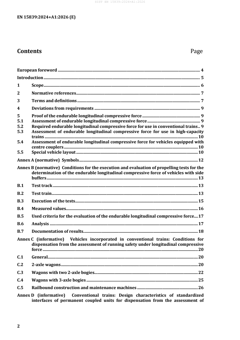
Contents Page
European foreword . 4
Introduction . 5
1 Scope . 6
2 Normative references . 7
3 Terms and definitions . 7
4 Deviations from requirements . 9
5 Proof of the endurable longitudinal compressive force . 9
5.1 Assessment of endurable longitudinal compressive force . 9
5.2 Required endurable longitudinal compressive force for use in conventional trains . 9
5.3 Assessment of endurable longitudinal compressive force for use in high-capacity
trains . 10
5.4 Assessment of endurable longitudinal compressive force for vehicles equipped with
centre couplers . 10
5.5 Special vehicle layout . 10
Annex A (normative) Symbols . 12
Annex B (normative) Conditions for the execution and evaluation of propelling tests for the
determination of the endurable longitudinal compressive force of vehicles with side
buffers . 13
B.1 Test track . 13
B.2 Test train . 13
B.3 Execution of the tests . 15
B.4 Measured values . 16
B.5 Used criteria for the evaluation of the endurable longitudinal compressive force. 17
B.6 Analysis . 17
B.7 Documentation of results. 18
Annex C (informative) Vehicles incorporated in conventional trains: Conditions for
dispensation from the assessment of running safety under longitudinal compressive
force . 20
C.1 General. 20
C.2 2-axle wagons . 20
C.3 Wagons with two 2-axle bogies . 22
C.4 Wagons with 3-axle bogies . 25
C.5 Railbound construction and maintenance machines . 26
Annex D (informative) Conventional trains: Design characteristics of standardized
interfaces of permanent coupled units for dispensation from the assessment of
running safety under longitudinal compressive force - Specification of interface with
diagonal buffers . 28
Annex E (informative) Requirements for the use of simulations as proof for endurable
longitudinal compressive force . 29
E.1 Introduction . 29
E.2 State of the art for the heavy rail system in ENs related to running dynamics . 29
E.3 Modelling for simulations . 29
E.4 Validation of the model . 31
E.5 Performance of simulations . 32
Annex F (informative) Scenarios for the assessment of endurable longitudinal compressive
force of a vehicle incorporated in a high-capacity train . 33
Annex G (informative) Vehicle incorporated in a high-capacity trains: conditions for
dispensation from the assessment of running safety under longitudinal compressive
force . 35
G.1 Introduction . 35
G.2 Wagons with 2 bogies . 35
G.3 Articulated wagons with 3 bogies . 36
Annex H (informative) Vehicles with centre couplers . 37
Bibliography . 38
European foreword
This document (EN 15839:2024+A1:2026) has been prepared by Technical Committee CEN/TC 256
“Railway applications”, the secretariat of which is held by DIN.
This European Standard shall be given the status of a national standard, either by publication of an
identical text or by endorsement, at the latest by March 2027, and conflicting national standards shall be
withdrawn at the latest by March 2027.
Attention is drawn to the possibility that some of the elements of this document may be the subject of
patent rights. CEN shall not be held responsible for identifying any or all such patent rights.
This document supersedes EN 15839:2012+A1:2015.
!Deleted text"
This document includes Amendment 1 approved by CEN on 29 June 2026.
The start and finish of text introduced or altered by amendment is indicated in the text by tags !".
This document has been prepared under a standardization request addressed to CEN by the European
Commission. The Standing Committee of the EFTA States subsequently approves these requests for its
Member States.
Any feedback and questions on this document should be directed to the users’ national standards body.
A complete listing of these bodies can be found on the CEN website.
According to the CEN-CENELEC Internal Regulations, the national standards organisations of the
following countries are bound to implement this European Standard: Austria, Belgium, Bulgaria, Croatia,
Cyprus, Czech Republic, Denmark, Estonia, Finland, France, Germany, Greece, Hungary, Iceland, Ireland,
Italy, Latvia, Lithuania, Luxembourg, Malta, Netherlands, Norway, Poland, Portugal, Republic of North
Macedonia, Romania, Serbia, Slovakia, Slovenia, Spain, Sweden, Switzerland, Türkiye and the United
Kingdom.
Introduction
Due to the operating conditions of braking or propelling, high longitudinal compressive force can occur
between coupled freight vehicles. This force can be safety-related especially in S-shaped curves with
small radii under some conditions depending also on the design of the vehicle and the coupling.
This document defines the acceptance process to be followed by vehicles that are operated in a way that
high longitudinal compressive force can occur in the trains.
The establishment of this document was based on currently existing rules, practices, and procedures to
define acceptance criteria ensuring running safety under the existing operating conditions. It provides a
defined assessment method between vehicle design, track layout and braking operation. Investigations
according to this document are not necessary if operating practice shows that running safety is achieved
without them.
The following principles are applied:
a) the railway system requires comprehensive technical rules to ensure an acceptable interaction
between vehicle and track;
b) due to the numerous national and international regulations, new railway vehicles are tested and
homologated before putting them into service. In addition, existing acceptance are checked when
operating conditions are extended;
c) in view of the significance of international traffic, the harmonization of existing regulations is
required. In some cases, additional rules are required as well: an update of existing regulations is
also needed due to the considerable progress achieved in the field of railway-specific methods for
measuring, evaluation, and data processing;
d) it is of particular importance that the existing level of safety and reliability is not compromised even
when changes in design and operating practices are demanded.
This document is derived in essential parts from UIC 530-2:2011, which is based on practical tests
performed in ERRI-B12.
Variations from the conditions specified in this document are allowed as specified by Article 7 of Directive
2016/797/EU.
For national or multilateral operations, variations to the defined conditions can be authorized.
1 Scope
This document defines the assessment of endurable longitudinal compressive force (LCF) of a vehicle.
The endurable longitudinal compressive force is a parameter depending on the vehicle design. It is used
to estimate the risk of derailment of a vehicle as a result of being subjected to longitudinal compressive
force, under operating conditions.
NOTE 1 As operating conditions can vary in several aspects (infrastructure, train configurations etc.), this
document defines uniform assessments of endurable longitudinal compressive force per vehicle in specific
operating conditions. The main assessment of endurable longitudinal compressive force for conventional trains is
derived from UIC 530-2:2011, which is based on practical tests performed in ERRI-B12. Assessments of endurable
longitudinal compressive force for high-capacity trains in this document are required by the methodology of
IRS 40421. IRS 40421 assesses operational train parameters.
This document applies to the following types of vehicles:
— single wagons;
— permanently coupled units with standard ends between the vehicles;
— permanently coupled units with diagonal buffers and screw couplers between the vehicles;
— permanently coupled units with a bar coupler between the vehicles;
— articulated units with 2-axle bogies;
— wagons with 3-axle bogies;
— low-floor wagons with eight or more axles (e.g. rolling road wagon);
— vehicles with centre couplers;
— railbound construction and maintenance machines as defined in EN 14033-1:2017.
NOTE 2 This document defines the acceptance process to be followed by vehicles that are operated in a way that
high longitudinal compressive force occur in the trains due to their operational environment (e.g. train composition,
brake mode, track layout).
The following vehicles are not in the scope of this document:
— locomotives and passenger rolling stocks;
— vehicles that are only operated in passenger trains.
NOTE 3 Locomotives, passenger rolling stocks and vehicles operated in passenger trains only are not in the scope
of this document as they either are subject to low longitudinal compressive force in operation or have sufficient
endurable longitudinal compressive force due to their axle load.
Acceptance criteria and test conditions as well as conditions for simulation are defined in this document.
Conditions for dispensation of the assessment of the endurable longitudinal compressive force are also
defined in this document.
This document applies principally to vehicles which operate without restrictions on tracks with a gauge
of 1 435 mm in Europe.
NOTE 4 The influence on railway systems using other gauges is not sufficiently understood to extend the scope
of this document to gauges other than 1 435 mm.
NOTE 5 For wagons with centre couplers, a need for assessment of derailment risk due to Longitudinal Forces
on other gauges (1 524 mm, 1 600 mm, 1 668 mm) has been expressed. The influence on railway systems using
other gauges is not sufficiently understood. This document only introduces some notions to assess it independently
from the gauge.
2 Normative references
The following documents are referred to in the text in such a way that some or all of their content
constitutes requirements of this document. For dated references, only the edition cited applies. For
undated references, the latest edition of the referenced document (including any amendments) applies.
EN 15551:2022, Railway applications — Railway rolling stock — Buffers
EN 15566:2022, Railway applications — Railway Rolling stock — Draw gear and screw coupling
EN 16235:2023, Railway applications — Testing for the acceptance of running characteristics of railway
vehicles - Freight wagons — Conditions for dispensation of freight wagons with defined characteristics from
on-track tests according to EN 14363
EN 17343:2023, Railway applications — General terms and definitions
3 Terms and definitions
For the purposes of this document, the terms and definitions given in EN 17343:2023, the symbols given
in Annex A, and the following apply.
ISO and IEC maintain terminology databases for use in standardization at the following addresses:
— ISO Online browsing platform: available at https://www.iso.org/obp/
— IEC Electropedia: available at https://www.electropedia.org/
3.1
torsional coefficient of vehicle body
relevant parameter for running safety under compressive forces and safety against derailment on twisted
track
Note 1 to entry: Test conditions for deriving the torsional coefficient of a carbody are defined in
EN 14363:2016+A2:2022.
3.2
safety against derailment on twisted track
safety of a vehicle against wheel climbing of a guiding wheel whilst negotiating a curved track with limit
conditions of twist
Note 1 to entry: Test conditions are defined in EN 14363:2016+A2:2022.
3.3
longitudinal compressive force
longitudinal force which is applied on a vehicle through its interfaces with flanking vehicles
Note 1 to entry: The longitudinal compressive force depends on many parameters such as the composition of the
train, the track layout, the driving manoeuvre, and dynamic parameters.
3.4
endurable longitudinal compressive force
longitudinal force which can be applied on a vehicle under defined conditions related to the flanking
wagons and the track layout without exceeding limits specified for wheel lift, lateral axle box force,
overlap of buffer plates and axle guard deformation
3.5
required endurable longitudinal compressive force
minimum endurable longitudinal compressive force required for a vehicle to be authorized for use in
defined operating conditions
3.6
standard end
specific design of the coupling end of a vehicle equipped with side buffers and screw coupling systems
Note 1 to entry: Geometric location of buffers and draw gear is specified in EN 16839:2022. Characteristics of
buffers are specified in EN 15551:2022, characteristics of screw coupling systems are specified in EN 15566:2022.
3.7
permanently coupled unit
unit consisting of several single vehicles which cannot be operated separately, each vehicle being fitted
with its own running gear
3.8
articulated unit
unit consisting of several elements connected with joints between adjacent elements where the elements
cannot be operated separately
3.9
conventional train
train including freight wagons and/or railbound construction and maintenance machines whose
composition characteristics (length, mass, brake mode, maximum speed…) are admitted in international
traffic
Note 1 to entry: IRS 40421 presents train compositions admitted in international traffic which are conventional
trains.
3.10
high-capacity train
train including freight wagons and/or railbound construction and maintenance machines whose
composition characteristics (length, mass, brake mode, maximum speed…) are not commonly admitted
in international traffic or not admitted yet in any European country
3.11
centre coupler
central buffer end coupling that works automatically for coupling two units together, at least
mechanically
Note 1 to entry: a standard on the Digital Automatic Coupler (DAC), which is a specific centre coupler for freight
operations, is under preparation.
3.13
railbound construction and maintenance machine
on-track machines and infrastructure inspection machines
3.14
on-track machine
OTM
machine specially designed for construction and maintenance of the track and infrastructure as a self-
propelling or as a hauled vehicle, when it is running on its own rail wheels
Note 1 to entry: Modes of the OTM are defined in EN 14033-1:2017.
Note 2 to entry: An OTM is designed to have characteristics necessary for the operation of track-based train
detection systems.
[SOURCE: EN 17343:2023, 3.1.7.8.1.1]
3.15
infrastructure inspection machine
self-propelled or hauled machine running on its own rail wheels for inspecting and measuring the
infrastructure
Note 1 to entry: Infrastructure inspection machines designed to be incorporated into passenger trains are not
considered as railbound construction machines.
Note 2 to entry: An infrastructure inspection machine measuring the tracks only is alternatively referred to as a
track recording machine (TRM).
[SOURCE: EN 17343:2023, 3.1.7.8.1.2]
4 Deviations from requirements
If deviating from some points of the requirements of this document for a particular assessment, these
deviations shall be reported and explained. Then, the influence on the assessment of the vehicle in terms
of the acceptance criteria shall be evaluated and recorded. The outcome of this study shall be considered
as an integral part of the requirements of this document when applied to the assessment process of the
vehicle, as long as evidence can be furnished that safety is at least the equivalent to that ensured by
complying with these rules.
5 Proof of the endurable longitudinal compressive force
5.1 Assessment of endurable longitudinal compressive force
The endurable longitudinal compressive force shall be determined either:
a) by performing propelling tests on the vehicle according to the specification in normative Annex B;
b) by performing simulations according to informative Annex E.
It is not necessary to assess the endurable longitudinal compressive force of vehicles which are not
operated in conventional trains or high-capacity trains and therefore are not subjected to high
longitudinal compressive force.
5.2 Required endurable longitudinal compressive force for use in conventional trains
For an unlimited operation in conventional trains, the vehicle shall have endurable longitudinal
compressive force higher than:
— 200 kN for vehicles or units equipped with single axle running gear;
— 240 kN for other vehicles.
NOTE These values are based on special test conditions defined in normative Annex B and proved to be
suitable for the running safety of conventional trains. The occurring longitudinal compressive force in operation
might exceed these values.
The vehicle may be designed in accordance with the conditions specified in Annex C. If it is the case,
neither test nor simulation are necessary to prove its running safety in conventional trains.
Vehicles not compliant with the conditions above could need operational restrictions for their use in
European networks.
5.3 Assessment of endurable longitudinal compressive force for use in high-capacity
trains
The longitudinal compressive force reached in operation depend on many different technical parameters
(e.g. train composition rules, driving rules, locomotive types, brake mode).
High-capacity trains might generate higher longitudinal compressive force than conventional trains.
Therefore, for vehicles incorporated in high-capacity trains, higher endurable longitudinal compressive
force than the one mentioned in 5.2 might be required.
The determination of the required endurable longitudinal compressive force of a vehicle under the
various operational conditions of high-capacity trains is not part of this document.
NOTE IRS 40421 Appendix B presents a methodology which helps to determine the occurring longitudinal
compressive force and to derive the required endurable longitudinal compressive force for a vehicle in a high-
capacity train.
The additional assessments described in informative Annex F and informative Annex G only apply for
vehicles used in high-capacity trains requiring higher endurable longitudinal compressive force than
specified in 5.2.
The informative Annex F proposes a list of scenarios for the assessment of endurable longitudinal
compressive force of a vehicle incorporated in a high-capacity train. These determined endurable
longitudinal compressive forces under the specified scenarios shall be documented in the technical
documentation of the vehicle.
5.4 Assessment of endurable longitudinal compressive force for vehicles equipped with
centre couplers
The informative Annex H gives information about the assessment methodology of endurable longitudinal
compressive force of vehicles equipped with centre couplers.
5.5 Special vehicle layout
5.5.1 Permanently coupled units consisting of 2-axle wagons with standard ends or diagonal
buffers
For permanently coupled units consisting of two 2-axle wagons with standard ends at the end of the unit:
— with standard ends at the permanently coupled interfaces; or
— with 2 diagonal buffers and draw gears according to Figure D.1 at the permanently coupled
interfaces;
each 2-axle wagon shall be assessed independently according to 5.1, 5.2 and 5.3, considering it is
equipped with standard ends at both ends.
If the height of each permanently coupled interface is more than 100 mm below the outer ends, the axle
loads of the unit shall be assessed under the effect of the required endurable longitudinal compressive
force according to 5.2 and 5.3 on straight track. The minimum axle load obtained shall be at least 50 % of
the minimum tare weight given in Figure C.1.
5.5.2 Permanently coupled units with bar couplers
In general, a unit equipped with bar couplers at the permanently coupled interfaces shall be assessed as
a whole according to 5.1, 5.2 and 5.3.
Deviating from this principle, each wagon of the unit can be assessed independently according to 5.1, 5.2
and 5.3, provided that it is equipped with standard ends at both ends if the following technical conditions
are fulfilled:
— all wagons of the unit are equipped with bogies;
— minimum distance between articulation points of the bar coupler;
— minimum static compressive strength in the direction of the centre of the bar coupler;
— minimum static tensile strength of the bar coupler;
— stored energy capacity of the bar coupler;
— height difference between end coupler and inner coupler location of the articulation point of the bar
coupler;
— presence of stabilization effect on the bar coupler;
— longitudinal play inside the bar coupler.
NOTE Technical conditions on these parameters regarding the bar coupler are given in UIC 572:2011.
Annex A
(normative)
Symbols
Table A.1 contains a summary of the symbols of the quantities and characteristic figures for testing of the
running safety of vehicles under longitudinal compressive force as well as supplementary information
and terms.
Table A.1 — Symbols
Symbol Significance Symbol Significance
Reference system on vehicle
x, y, z Direction of coordinates
i Wheelset j Wheel (vehicle side, 1: right, 2: left)
General symbols (represented using the example of the quantity y)
dy Difference y Endurable value
sus
Assessment values
dz Wheel lift, wheel ij F Longitudinal compressive force,
ij Lxk
measured on end k
dy Deformation of axle guard, wheel, ij H Lateral axle box force, wheelset i
Aij i
dy Lateral displacements of buffers, end k Y/Q ratio of lateral and vertical wheel force
Pk
Other quantities
Vehicle
+
2a* Distance between wheelsets (2-axle 2a Distance between wheelsets within a
vehicles), Distance between bogies bogie
(bogie vehicles)
2b Lateral distance between wheel-rail 2b Lateral distance between primary
A z
contact points suspensions
D Nominal wheel diameter σa Lateral play between wheelset and guide
LoB Length over buffer 2b Lateral distance of side bearers
G
Ovh Distance between coupling plane and dZ Vertical gap of side bearers
G
centre of adjacent running gear
c * Torsional coefficient of car body hK Height of buffer and draw hook above
t
top of rail
R Radius of the spherical buffer head Bw Width of the buffer plate
P
surface
Q Mean vertical wheel force
Annex B
(normative)
Conditions for the execution and evaluation of propelling tests for the
determination of the endurable longitudinal compressive force of vehicles
with side buffers
B.1 Test track
The S-shaped test track (see Figure B.1) comprises curves of a nominal radius R = 150 m separated by a
section of straight track of a nominal length of 6 m.
Dimensions in metres
Key
L minimal length of the track section
R track radius
1 entry of curve
2 exit of curve
3 entry of reverse curve
4 exit of reverse curve
Figure B.1 — Layout of the test track
The test track is flat (i.e. without installed cant). The track quality is equivalent to a track maintained
normally. The average gauge is between 1 450 mm to 1 465 mm. Lateral track shift during the tests shall
not occur. Therefore, special lateral track fixing could be necessary.
B.2 Test train
B.2.1 Standard configuration
For the purpose of the tests, use shall be made of wagons with the characteristics given in Table B.1.
Table B.1 — Conditions for the test vehicle and flanking wagons during testing
Leading wagon Test vehicle Trailing wagon
a
Typical example wagon literal marking Fcs - wagon literal marking Rs
a
or Tds
Type 2-axle wagon - 4-axle bogie wagon
Length over 9,64 m - 19,90 m
buffers:
Wheelbase: 6,00 m -
Distance between - 13,00 m
bogie pivots:
Axle Load Loaded approximately to Tare weight Loaded approximately to
load limit load limit
Vertical distance approx. 80 mm
between buffer
Differences due to the tare to laden deflection of the test vehicle are
centre lines of
permissible.
loaded flanking
and empty test
vehicle
Type of buffers Characteristic according Type as specified Characteristic according
to EN 15551:2022, for the vehicle, to EN 15551:2022,
Category A, end stroke Radius according Category A, end stroke
force 590 kN, spherical to the specified force 590 kN, spherical
buffer head surface buffer type buffer head surface
R = 1 500 mm R = 1 500 mm
P P
Non rotating buffer head Non rotating buffer head
Condition of Lightly greased before Lightly greased Lightly greased before
surface of buffer entering the measuring before entering the entering the measuring
heads section to provide a low measuring section section to provide a low
friction surface to provide a low friction surface
friction surface
Previously used in Previously used in
revenue service without No visual wear of revenue service without
surface damage the surface at the surface damage
beginning of the
test
Coupling The screw couplers between the test vehicle and the flanking wagons are
conditions on to be tightened in such a way that when on the straight track the buffer
straight track plates are in contact without pre-tensioning.
a
See informative Annex E for wagon characteristics.
Figure B.2 shows an example of a test train with the above-mentioned standard configuration.
Key
1 locomotive 7 measuring coach
2 intermediate wagon 8 direction of movement
3 4-axle flanking wagon (trailing wagon) 9 unbraked trainset
4 2-axle flanking wagon (leading wagon) 10 braked trainset
5 test vehicle 11 longitudinal force measuring device for F
Lxi
6 braking unit(s) (e.g. group of wagons or
locomotive)
Figure B.2 — Example for a test train configuration
It is essential that the 2-axle flanking wagon is operated in front of the test vehicle.
To determine the longitudinal compressive force, use shall be made of 2-axle or 4-axle intermediate
wagons equipped at one end with a force measuring device.
B.2.2 Supplementary configuration for 2-axle vehicles with LoB ≥ 15,75 m
For these vehicles, an additional variant shall be investigated: In this case the (loaded) flanking wagons
are characterized by the same geometric features (LoB and wheelbase) and shall be fitted with the same
buffer type as the (empty) vehicle to be examined. The conditions for the surface of buffer heads and the
coupling on straight track are the same as specified in Table B.1.
B.3 Execution of the tests
The test train shall be propelled along the specified S-shaped curve at a speed of 4 km/h to 8 km/h with
a longitudinal compressive force that remains approximately constant. The tests shall be repeated with
the longitudinal compressive force increased until one of the evaluation criteria mentioned under B.5 is
reached or exceeded. For vehicles intended to be used only in conventional trains, if 280 kN is reached,
without exceeding any of the evaluation criteria the longitudinal compressive force does not need to be
increased above this level. For vehicles intended to be used in high-capacity trains, the longitudinal
compressive force shall be increased until one of the evaluation criteria is exceeded.
For the acceptance of a vehicle, it is sufficient to show compliance with the criteria for the minimum
required endurable longitudinal compressive force given in 5.2.
At least 20 suitable tests are to be carried out for the determination of the linear regression line according
to B.6 with different longitudinal compressive force. In at least 10 of these tests, the required endurable
longitudinal compressive force as defined in 5.2 for a conventional train should be exceeded by about
10 %.
Damage on the buffer head impact surfaces, which can occur during a test run, is to be removed prior to
each new test run. In the course of the 20 tests, five consecutive tests shall be carried out with the
required endurable longitudinal compressive force without any damage which leads to changing the
buffers or the need for buffer plate maintenance and without exceeding the criteria according to B.5.
Buffer-plate pairs shall be replaced where, as a result of abrasion or deformation, results obtained differ
considerably from those previously recorded.
B.4 Measured values
B.4.1 Measurements during the tests
As a minimum, the following values shall be measured and recorded during the tests:
— longitudinal compressive force F in the test train;
Lxk
— wheel elevation dz of all wheels on the test vehicle;
ij
— lateral forces on axle-boxes H of all wheelsets of the test vehicle;
i
— deformation of axle guards dy of all wheels on the test vehicle (only on vehicles fitted with axle
Aij
guards);
— lateral displacements dy , dy of the buffers between the flanking wagons and test vehicle;
P1 P2
— position of the vehicle along the track.
Key
1 running direction
2 4-axle flanking wagon
3 2-axle flanking wagon
4 device to measure the position of the vehicle along the track
Figure B.3 — Arrangement of measuring devices during the test
B.4.2 Other measurements
Other measurements and inspections shall be performed:
— measurement of the static force-deflection characteristic of the buffers of the flanking wagons and
the test vehicle to verify the correct test conditions (see Table B.1);
— measurements of the track geometry before and after the tests to verify that the track conditions
were compliant with B.1;
— inspection of the vehicle condition before and after the test to detect possible damage (e.g.
measurements of the lateral and longitudinal clearances between axle box and axle guard);
— measurements of the buffer heights above rail level on the flanking wagons and the test vehicle to
verify the required height difference (see Table B.1).
B.5 Used criteria for the evaluation of the endurable longitudinal compressive
force
The endurable longitudinal compressive force is defined by reaching one of the following limits:
— elevation of a non-guiding wheel dz = 50 mm over a distance of ≥ 2 m;
ij,lim
1)
— axle-guard deformation dy = 22 mm measured 380 mm from the lower edge of the sole-bar ;
Aij,lim
— lateral axle box force H (2m) = 25 + 0,6 x 2Q (kN) with Q being the mean vertical wheel force ;
lim 0 0
— minimum horizontal overlap of buffer plates dy = 25 mm;
P,lim
— when using the supplementary train configuration for long 2-axle freight wagons (see B.2.2):
climbing of guiding wheels dz = 5 mm.
ij,lim
B.6 Analysis
For each test, it is necessary to evaluate:
— H value sustained over a distance of 2 m;
i
— dz value sustained over a distance of 2 m;
ij
— F ;
LXk
— dy (for 2-axle vehicles with guards);
Aij
— dy ;
Pk
when using the supplementary train configuration for long 2-axle vehicles (see B.2.2): dz as a value of
ij
the climbing of the guiding wheel.
The values calculated shall be presented in graphical form as a function of the longitudinal compressive
force F .
LX
1)
Evaluation and analysis only for 2-axle vehicles with guards. This limit applies to standardised axle guard defined
in UIC 517:1989 and can be modified for other designs.
To calculate the endurable longitudinal compressive force, the linear regression line formulas shall be
defined for the quantities to be measured dz , dy , dy and H in a relevant range, where a linear
ij Aij P i
dependency is obvious.
The endurable longitudinal compressive force shall be defined as the value found on the abscissa for the
point of intersection between the linear regression line and the evaluation criterion (see Figure B.4).
Dimensions in Millimetres
Key
dz maximum wheel lift per trial run of the wheel lifts dzij of the vehicle under assessment
F longitudinal compressive force as applied in the respective trial run
L
FLXsus endurable longitudinal compressive force
Figure B.4 — Regression analysis
The evaluation criterion giving the lowest value for F shall determine the endurable longitudinal
LXsus
compressive force.
B.7 Documentation of results
B.7.1 General
The results of the propelling tests shall be included in a report with the following information:
— the identification of the assessed vehicle;
— the version of the EN 15839 used;
— the method used (if the standard includes several);
— any deviations from the procedure;
— any unusual features observed;
— the date of the test.
It is recommended that the test report is copied to a central database (currently at UIC) to create a basis
for future test dispensations using a reference vehicle according to Annex C.
B.7.2 Characteristics of the track on which the tests were carried out
For the three sections of the test track (left-hand curve, straight track section and right-hand curve) the
following parameters shall be listed:
— mean curve radius (in metres);
— length of section (in metres);
— mean track gauge (in millimetres).
B.7.3 Characteristics of the test vehicle
The test vehicle shall be described using the following parameters:
— length over buffers (in metres);
— wheelbase (in metres);
— tare (in tons);
— torsional coefficient c * of the vehicle body (in kNmm /rad);
t
— diameter of the wheel (mm);
— type of axle guard;
— type of suspension (spring);
— stiffness of suspension c and c (kN/mm);
z1 z2
— type of buffers;
— buffer plate radius (mm);
— difference between the heights of the buffer centrelines on the flanking wagons and the test vehicle
(mm).
B.7.4 Test results
The report shall contain the following results:
— endurable longitudinal compressive force determined as F (kN);
LXsus
— evaluation criterion decisive for the determination of F ;
LXsus
— analysis according to B.6;
— number of tests;
— number of tests with wheel elevations;
— number of tests with wheel elevations > 40 mm;
— necessity of buffer replacements and reason;
— if applicable: lateral track displacement and its amount.
Annex C
(informative)
Vehicles incorporated in conventional trains: Conditions for dispensation
from the assessment of running safety under longitudinal compressive
force
C.1 General
For vehicles with specific parameters defined in this informative Annex evidence already exists that they
can be operated safely in conventional trains and that they withstand the required endurable longitudinal
compressive force.
Another possibility to demonstrate compliance with the requirements for operation in conventional
trains is the reference to a similar vehicle regarding the relevant parameters given in C.2, C.3, C.4 and C.5
which showed acceptable results in tests.
NOTE A database with test results from wagons which passed the propelling test is available in UIC 530-
2:2011, Appendix G.3 (see UIC-website www.uic.org/spip.php?article1521).
C.2 2-axle wagons
The parameters presented in Table C.1 and Figure C.1 shall be met for dispensation from propelling tests
for 2-axle vehicles.
...