

EN 13121-3:2026
(Main)GRP tanks and vessels for use above ground - Part 3: Design and workmanship
- Abstract
This document gives requirements for the design, fabrication, inspection, testing and verification of GRP tanks and vessels with or without thermoplastics lining for storage or processing of fluids, factory made or site built, non-pressurized or pressurized up to 10 bar, for use above ground. Further requirements are presented in normative Annex G.
The terms vessels and tanks as used in this document include branches up to the point of connection to pipe work or other equipment by bolting and supports, brackets or other attachments bonded directly to the shell.
Fatigue is not considered a design criterion, as keeping strains below the limit strain inherently prevents fatigue failure. This document is applicable to vessels and tanks exposed to temperatures between -40 °C and 120 °C.
This document does not apply to:
- tanks and vessels for the transport of fluids;
- underground storage tanks;
- spherical vessels;
- vessels and tanks of irregular shape;
- tanks and vessels with double containment where the double wall is considered structural;
- tanks and vessels which are subject to the risk of explosion, or failure of which can cause an emission of radioactivity;
- specification for fibre reinforced cisterns of one piece and sectional construction for the storage, above ground, of cold water (see EN 13280).
- Status
- Not Published
- Publication Date
- 16-Aug-2026
- Technical Committee
- CEN/TC 210 - GRP tanks and vessels
- Drafting Committee
- CEN/TC 210 - GRP tanks and vessels
- Current Stage
- 5060 - Closure of Vote - Formal Approval
- Start Date
- 18-Jun-2026
- Completion Date
- 18-Jun-2026


EN 13121-3:2026 is a CEN standard for GRP tanks and vessels used above ground. It specifies how to design, fabricate, inspect, test, and verify GRP tanks and vessels with or without thermoplastics lining for storage or processing of fluids. The document is aimed at manufacturers, designers, inspectors, purchasers, and approval bodies that need a common basis for structural design, workmanship, and documentation.
What does EN 13121-3:2026 specify?
EN 13121-3:2026 specifies requirements for GRP tanks and vessels above ground, including factory-made and site-built units, whether non-pressurized or pressurized up to 10 bar. It also applies to vessels and tanks with branches up to the connection point and to attachments bonded directly to the shell.
The scope covers equipment exposed to temperatures between -40 °C and 120 °C. Fatigue is not used as a design criterion in this document, because the design approach is based on keeping strains below the limit strain.
The standard excludes:
- transport tanks and vessels for fluids
- underground storage tanks
- spherical vessels
- irregularly shaped vessels and tanks
- double containment where the double wall is structural
- tanks and vessels subject to explosion risk or possible radioactive release
- fibre reinforced cisterns for above-ground storage of cold water, which are covered by EN 13280
EN 13121-3:2026 is organized into clauses for scope, references, terms, symbols, documentation, materials, mechanical properties, design strain and loadings, design, design analysis, supports, seismic loading, anchorage, structures and fittings, local load analysis, quality control, and marking. Its annexes add product testing, calculation methods, test methods, laminator approval, design verification methods, and water-related requirements.
| Annex | What it covers |
|---|---|
| Annex A | Product testing for serial or batch production |
| Annex B | Lamina and laminate thickness, modulus, stiffness, and strain calculations |
| Annex C | Tests for pressureless tanks and vessels and hydraulic pressure testing |
| Annex D | Material and joint test methods, including welds, laminates, hardness, resistivity, creep, HDT, and pull-off strength |
| Annex E | Approval testing of laminators |
| Annex F | Typical methods, general requirements, important determination results, and design factors |
| Annex G | Additional requirements for design and manufacturing, effects on water and food, recycling, and storage of substances hazardous to water |
What are the key requirements of EN 13121-3:2026?
EN 13121-3:2026 combines material rules, design calculations, workmanship controls, and verification steps. In practice, a project team uses it to define the laminate, check loads and stability, document the design, and prove the finished tank or vessel by inspection and testing.
Documentation and process information
Clause 5 requires the manufacturer to collect the process requirements and prepare the technical information and final documentation needed for the tank or vessel. This matters because the design, material selection, fabrication, and inspection records have to match the intended service before work starts and before handover.
Materials and physical properties
Clause 6 covers the chemical protective barrier, thermoplastics linings, resin-based linings, flammability, and electrical resistivity. Clause 7 then links those materials to measurable properties such as heat deflection temperature, laminate construction, thickness, inter-laminar shear strength, peel strength, pull-off strength, and allowable design factors.
In practice, this is the section that tells the manufacturer what properties must be checked before a laminate or liner is used in service. It is also where the document distinguishes between basic and advanced design approaches.
Design strain and laminate resistance
Clause 8 sets the framework for limit design strain and limit design laminate loadings, and it gives methods for deriving mechanical values from laminates with or without experimental test data. This matters because the design checks are based on the actual laminate behavior, not on generic material assumptions.
The clause also shows how laminate thickness and test strain fit into the design proof. For the reader, that means the laminate build-up must be known well enough to calculate and justify its load capacity.
Loads and verification method
Clause 9 covers external loads such as snow, wind, seismic actions, insulation loads, loads from connections, agitation, inadequate venting, personnel loading, and temperature effects. It uses a partial factor method, so the load combinations and the factored actions are part of the design proof.
This is important in practice because the vessel is not designed only for internal pressure. The design also has to account for the real installation environment and the way different actions combine.
Geometry-specific design checks
Clause 10 gives the detailed design checks for cylinders, conical shells, dished ends, flat bottoms, skirts, seams, openings, branches, compensating laminates, large diameter pipes, and pipe fittings. Clause 11 covers bolted flange connections, including full face flanges, stub flanges with backing rings, and butt and strap jointed flanges.
This is the core of the document for structural design work. It tells the designer where buckling, local reinforcement, seam construction, flange loads, and joint details have to be checked, and when more advanced analysis or experimental verification is needed.
Supports, anchorage, and handling features
Clauses 12, 14, and 15 deal with supports, anchorage, internal and external fittings, lifting devices, and trunnions. These clauses matter because the shell has to carry not only fluid load but also support reactions, uplift, handling loads, and loads from saddles, skirts, rings, and lugs.
For horizontal vessels, the document gives saddle support arrangements and the need for free movement or controlled expansion. For vertical vessels, it addresses leg supports, ring supports, ring girders, skirt supports, and anchor bolts.
Quality control and final acceptance
Clause 17 covers works requirements, raw material storage, manufacturing conditions, documentation, fabrication of thermoplastics liners, inspection and testing after fabrication, and experimental design verification for pressure vessels. It also includes visual and dimensional inspection and records for materials, manufacturing, and quality control.
Clause 18 lists the marking information that has to accompany each tank or vessel. In practice, this gives the handover data that buyers, inspectors, and maintenance teams need to identify the equipment and its design limits.
What terms does EN 13121-3:2026 define?
EN 13121-3:2026 defines the roles and pressure terms used throughout the design and inspection rules.
- Manufacturer - the organization that designs, manufactures, and tests the vessel or tank to this document.
- Purchaser - the organization or individual that buys the finished tank or vessel and states the process requirements.
- Authorized inspecting authority - the body that may check compliance with the document, used when PS is at or below 0,5 bar.
- Notified body - the certificated organization listed by the European Commission of pressure equipment, used when PS is above 0,5 bar.
- Internal inspection authority - an inspector from the manufacturer who is independent from the workshop.
- Vessel - a closed container under applied pressure or vacuum, including branches up to the first flanged connection.
- Tank - a container for fluids that is only subject to hydrostatic head and is freely vented to atmosphere, including branches up to the first flanged connection.
- PS - the maximum allowable pressure specified by the manufacturer.
- TS - the maximum or minimum allowable temperature specified by the manufacturer.
- PT - the test pressure applied during pressure testing.
Who uses EN 13121-3:2026?
EN 13121-3:2026 is used by GRP tank and vessel manufacturers, structural and mechanical designers, and fabrication teams that build laminate shells and lined constructions. It is also used by quality managers, inspectors, purchasers, and notified bodies when they need to check design data, fabrication records, inspection evidence, and test results.
In practice, it supports tasks such as specifying a laminate, checking support and anchorage loads, approving thermoplastics welds, reviewing flange details, and accepting final documentation.
What changed in EN 13121-3:2026 from the previous edition?
EN 13121-3:2026 supersedes EN 13121-3:2016.
Which standards are used with EN 13121-3:2026?
EN 13121-3:2026 relies on a set of related standards for materials, design actions, steel parts, welding, testing, and calibration.
- EN 13121-1, EN 13121-2, EN 13121-4 - the companion parts for raw materials, chemical resistance, and delivery, installation, and maintenance.
- EN 1990, EN 1991-1-3, EN 1991-1-4, EN 1991-4, EN 1998-1 - basis of structural design and the action sets for snow, wind, tanks, and seismic design.
- EN 1993-1-1, EN 1993-1-6, EN 13445-3 - steel design and shell stability rules used where steel backing rings, flanges, or other steel parts are checked.
- EN 13067 - qualification of plastics welding personnel for thermoplastics welded assemblies.
- EN 59, EN ISO 75-2, EN ISO 291, EN ISO 527-4, EN ISO 1172, EN ISO 2592, EN ISO 3915, EN ISO 7500-1, EN ISO 9513, EN ISO 11357-2, EN ISO 14125, EN ISO 14692-3, ISO 48-2, ASTM D4541 - test, conditioning, and calibration methods used for hardness, temperature resistance, tensile and flexural properties, glass content, flash point, resistivity, machine calibration, extensometer calibration, DSC, piping system design, rubber hardness, and pull-off strength.
- EN 10025-2 - the steel grade reference for S235JR used in a backing ring context.
- EN 13555:2021 - the gasket seating stress reference used in flange design.
What does the EN 13121-3:2026 document contain?
EN 13121-3:2026 contains design equations, load combinations, figures, and tables for the full structural design of GRP tanks and vessels. It gives methods for cylinders, cones, dished ends, flat bottoms, skirts, saddles, openings, branches, and flanges, together with buckling and stability checks.
The document also contains detailed annexes for testing and verification. Annex C gives pressure and hydraulic test methods, Annex D gives material and joint test methods, Annex E covers laminator approval, and Annex F provides design factors and calculation approaches used in verification work.
Several tables and figures support practical fabrication and checking work, including flange and bolt details, support arrangements, acceptable imperfections, dimensional tolerances, and the geometry of critical design regions. For engineers and inspectors, these parts are the working material used for design review, testing, and acceptance rather than general background text.
Relations
- Effective Date
- 28-Jan-2026
- Effective Date
- 28-Jan-2026
- Effective Date
- 28-Jan-2026
- Effective Date
- 28-Jan-2026
- Effective Date
- 28-Jan-2026
- Effective Date
- 28-Jan-2026
- Effective Date
- 28-Jan-2026
- Effective Date
- 28-Jan-2026
- Effective Date
- 28-Jan-2026
- Effective Date
- 28-Jan-2026
- Effective Date
- 28-Jan-2026
- Effective Date
- 28-Jan-2026
- Effective Date
- 28-Jan-2026
- Effective Date
- 28-Jan-2026
- Effective Date
- 28-Jan-2026
Get Certified
Connect with accredited certification bodies for this standard

Institut za varilstvo d.o.o. (Welding Institute)
Slovenia's leading welding institute since 1952. ISO 3834, EN 1090, pressure equipment certification, NDT personnel, welder qualification. Only IIW Au
Sponsored listings
Frequently Asked Questions
EN 13121-3:2026 is a draft published by the European Committee for Standardization (CEN). Its full title is "GRP tanks and vessels for use above ground - Part 3: Design and workmanship". This standard covers: This document gives requirements for the design, fabrication, inspection, testing and verification of GRP tanks and vessels with or without thermoplastics lining for storage or processing of fluids, factory made or site built, non-pressurized or pressurized up to 10 bar, for use above ground. Further requirements are presented in normative Annex G. The terms vessels and tanks as used in this document include branches up to the point of connection to pipe work or other equipment by bolting and supports, brackets or other attachments bonded directly to the shell. Fatigue is not considered a design criterion, as keeping strains below the limit strain inherently prevents fatigue failure. This document is applicable to vessels and tanks exposed to temperatures between -40 °C and 120 °C. This document does not apply to: - tanks and vessels for the transport of fluids; - underground storage tanks; - spherical vessels; - vessels and tanks of irregular shape; - tanks and vessels with double containment where the double wall is considered structural; - tanks and vessels which are subject to the risk of explosion, or failure of which can cause an emission of radioactivity; - specification for fibre reinforced cisterns of one piece and sectional construction for the storage, above ground, of cold water (see EN 13280).
This document gives requirements for the design, fabrication, inspection, testing and verification of GRP tanks and vessels with or without thermoplastics lining for storage or processing of fluids, factory made or site built, non-pressurized or pressurized up to 10 bar, for use above ground. Further requirements are presented in normative Annex G. The terms vessels and tanks as used in this document include branches up to the point of connection to pipe work or other equipment by bolting and supports, brackets or other attachments bonded directly to the shell. Fatigue is not considered a design criterion, as keeping strains below the limit strain inherently prevents fatigue failure. This document is applicable to vessels and tanks exposed to temperatures between -40 °C and 120 °C. This document does not apply to: - tanks and vessels for the transport of fluids; - underground storage tanks; - spherical vessels; - vessels and tanks of irregular shape; - tanks and vessels with double containment where the double wall is considered structural; - tanks and vessels which are subject to the risk of explosion, or failure of which can cause an emission of radioactivity; - specification for fibre reinforced cisterns of one piece and sectional construction for the storage, above ground, of cold water (see EN 13280).
EN 13121-3:2026 is classified under the following ICS (International Classification for Standards) categories: 23.020.10 - Stationary containers and tanks. The ICS classification helps identify the subject area and facilitates finding related standards.
EN 13121-3:2026 has the following relationships with other standards: It is inter standard links to EN ISO 7439:2023, EN ISO 23908:2025, EN ISO 18113-1:2024, EN ISO 11197:2019, EN ISO 14155:2020, EN ISO 5361:2023, EN ISO 5840-1:2021, EN ISO 14708-5:2022, EN ISO 14630:2024, EN ISO 17664-1:2021, EN ISO 80369-7:2021, EN ISO 11608-1:2022, EN ISO 10651-4:2023, EN ISO 14708-3:2022, EN ISO 20417:2021. Understanding these relationships helps ensure you are using the most current and applicable version of the standard.
EN 13121-3:2026 is associated with the following European legislation: EU Directives/Regulations: 2014/68/EU; Standardization Mandates: M/071, M/601. When a standard is cited in the Official Journal of the European Union, products manufactured in conformity with it benefit from a presumption of conformity with the essential requirements of the corresponding EU directive or regulation.
EN 13121-3:2026 is available in PDF format for immediate download after purchase. The document can be added to your cart and obtained through the secure checkout process. Digital delivery ensures instant access to the complete standard document.
Standards Content (Sample)
SLOVENSKI STANDARD
oSIST prEN 13121-3:2022
01-oktober-2022
Nadzemni rezervoarji in posode iz umetnih mas, ojačanih s steklenimi vlakni - 3.
del: Konstruiranje in izdelava
GRP tanks and vessels for use above ground - Part 3: Design and workmanship
Oberirdische GFK-Tanks und -Behälter - Teil 3: Auslegung und Herstellung
Réservoirs et récipients en PRV pour applications hors sol - Partie 3 : Conception et
fabrication
Ta slovenski standard je istoveten z: prEN 13121-3
ICS:
23.020.10 Nepremične posode in Stationary containers and
rezervoarji tanks
oSIST prEN 13121-3:2022 en,fr,de
2003-01.Slovenski inštitut za standardizacijo. Razmnoževanje celote ali delov tega standarda ni dovoljeno.
oSIST prEN 13121-3:2022
oSIST prEN 13121-3:2022
DRAFT
EUROPEAN STANDARD
prEN 13121-3
NORME EUROPÉENNE
EUROPÄISCHE NORM
September 2022
ICS 23.020.10 Will supersede EN 13121-3:2016
English Version
GRP tanks and vessels for use above ground - Part 3:
Design and workmanship
Réservoirs et récipients en PRV pour applications hors Oberirdische GFK-Tanks und -Behälter - Teil 3:
sol - Partie 3 : Conception et fabrication Auslegung und Herstellung
This draft European Standard is submitted to CEN members for enquiry. It has been drawn up by the Technical Committee
CEN/TC 210.
If this draft becomes a European Standard, CEN members are bound to comply with the CEN/CENELEC Internal Regulations
which stipulate the conditions for giving this European Standard the status of a national standard without any alteration.
This draft European Standard was established by CEN in three official versions (English, French, German). A version in any other
language made by translation under the responsibility of a CEN member into its own language and notified to the CEN-CENELEC
Management Centre has the same status as the official versions.
CEN members are the national standards bodies of Austria, Belgium, Bulgaria, Croatia, Cyprus, Czech Republic, Denmark, Estonia,
Finland, France, Germany, Greece, Hungary, Iceland, Ireland, Italy, Latvia, Lithuania, Luxembourg, Malta, Netherlands, Norway,
Poland, Portugal, Republic of North Macedonia, Romania, Serbia, Slovakia, Slovenia, Spain, Sweden, Switzerland, Türkiye and
United Kingdom.
Recipients of this draft are invited to submit, with their comments, notification of any relevant patent rights of which they are
aware and to provide supporting documentation.
Warning : This document is not a European Standard. It is distributed for review and comments. It is subject to change without
notice and shall not be referred to as a European Standard.
EUROPEAN COMMITTEE FOR STANDARDIZATION
COMITÉ EUROPÉEN DE NORMALISATION
EUROPÄISCHES KOMITEE FÜR NORMUNG
CEN-CENELEC Management Centre: Rue de la Science 23, B-1040 Brussels
© 2022 CEN All rights of exploitation in any form and by any means reserved Ref. No. prEN 13121-3:2022 E
worldwide for CEN national Members.
oSIST prEN 13121-3:2022
prEN 13121-3:2022 (E)
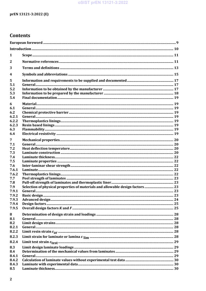
Contents
European foreword . 9
Introduction . 10
1 Scope . 11
2 Normative references . 11
3 Terms and definitions . 13
4 Symbols and abbreviations . 15
5 Information and requirements to be supplied and documented . 17
5.1 General . 17
5.2 Information to be obtained by the manufacturer . 17
5.3 Information to be prepared by the manufacturer . 18
5.4 Final documentation . 19
6 Material . 19
6.1 General . 19
6.2 Chemical protective barrier . 19
6.2.1 General . 19
6.2.2 Thermoplastics linings . 19
6.2.3 Resin based linings . 19
6.3 Flammability . 19
6.4 Electrical resistivity . 19
7 Mechanical properties . 20
7.1 General . 20
7.2 Heat deflection temperature. 20
7.3 Laminate construction . 20
7.4 Laminate thickness . 22
7.5 Laminate properties . 22
7.6 Inter-laminar shear strength . 22
7.6.1 Laminate . 22
7.6.2 Thermoplastics linings . 22
7.7 Peel strength of laminates . 23
7.8 Pull-off strength of laminates and thermoplastic liner . 23
7.9 Selection of physical properties of materials and allowable design factors . 23
7.9.1 General . 23
7.9.2 Basic design . 23
7.9.3 Advanced design . 24
7.9.4 Design factors . 25
7.9.5 Overall design factors K and F . 25
8 Determination of design strain and loadings . 28
8.1 General . 28
8.2 Limit design strains . 28
8.2.1 General . 28
8.2.2 Limit resin strain ε . 28
ar
8.2.3 Limit strain for laminate or lamina ε . 28
lim
8.2.4 Limit test strain ε . 29
test
8.3 Limit design laminate loadings . 29
8.4 Determination of the mechanical values from laminates . 29
8.4.1 General . 29
8.4.2 Calculation of laminate values without experimental test data . 30
8.4.3 Laminate with experimental data . 30
8.5 Laminate thickness . 30
oSIST prEN 13121-3:2022
prEN 13121-3:2022 (E)
9 Design . 31
9.1 Introduction . 31
9.2 Determination of external loads . 31
9.2.1 Snow loads . 31
9.2.2 Wind loads . 31
9.2.3 Seismic loads . 32
9.2.4 Insulation loads . 34
9.2.5 Loads resulting from connections . 34
9.2.6 Agitation . 34
9.2.7 Pressure due to inadequate venting . 34
9.2.8 Personnel loading . 34
9.2.9 Internal stresses in vessels and tanks due temperatures . 35
9.3 Verification by the partial factor method . 35
9.3.1 General . 35
9.3.2 Dimensioning by using (A ⋅γ )-factored loads. 40
F,i
9.4 Drawings and design calculations . 41
9.5 Design details . 41
9.5.1 Design temperature TS . 41
9.5.2 Pressure . 41
10 Design analysis . 42
10.1 Symbols and units . 42
10.2 Vertical vessels or tanks, cylinders under loads (t < 0,01∙D) . 45
10.2.1 Circumferential loadings . 45
10.2.2 Combined axial loading . 45
10.3 Cylindrical shells subject to compressive loadings — critical buckling criteria. 46
10.3.1 General . 46
10.3.2 Critical axial buckling load . 46
10.3.3 Critical circumferential buckling pressure . 47
10.3.4 Combined axial and radial compressive loadings . 47
10.3.5 Critical buckling pressure for cylindrical shell stiffened with external or internal rings. 48
10.4 Conical shells . 50
10.4.1 General requirements. 50
10.4.2 Shallow conical ends . 51
10.4.3 Conical ends subject to internal pressure . 52
10.4.4 Conical ends subject to external pressure . 53
10.4.5 Shell conical covers . 55
10.5 Dished end . 56
10.5.1 General requirements. 56
10.5.2 Dished ends subject to internal pressure . 57
10.5.3 Stability for dished ends subject to external pressure . 58
10.6 Design of flat bottoms and skirts for vertical tanks and vessels . 59
10.6.1 Definitions . 59
10.6.2 Fully supported, flat bottom tanks . 59
10.6.3 Vessels with flat bases subjected to pressure . 66
10.6.4 Dished bottom and conical bottom configurations . 66
10.7 Circumferential seams for cylindrical joints . 75
10.7.1 General . 75
10.7.2 Construction without thermoplastics liner . 78
10.7.3 Construction with thermoplastics liner . 78
10.8 Openings, branches and compensating laminate . 78
10.8.1 General . 78
10.8.2 Symbols . 79
10.8.3 Compensation requirements for openings . 79
10.8.4 Pull out load from nozzles . 86
10.8.5 Prevention of failure in peel . 86
10.8.6 Pad connections . 86
oSIST prEN 13121-3:2022
prEN 13121-3:2022 (E)
10.8.7 Screwed connections . 88
10.8.8 Access and inspecting openings . 88
10.8.9 Gusset on branches . 88
10.9 Flat Panels or Blind flanges . 88
10.9.1 General . 88
10.9.2 Symbols . 89
10.9.3 Circular panels . 89
10.10 Horizontal tanks and vessels . 92
10.10.1Types of supports . 92
10.10.2Symbols . 94
10.10.3Unit loads of the cylindrical shell . 95
10.10.4Unit loads on saddle position. 101
10.10.5Unit loads for horizontal loads at the vessel . 108
10.11 Large diameter pipes and pipe fittings . 109
10.11.1General . 109
10.11.2Joints . 109
10.11.3Elbows . 110
10.11.4Large cut-outs and Tees . 110
11 Bolted flange connections . 113
11.1 General . 113
11.2 Full face flanges design . 119
11.2.1 General . 119
11.2.2 Symbols . 120
11.2.3 Pipe loads on flanges. 122
11.2.4 Gasket load and bolt torque . 122
11.2.5 Summary of loads . 123
11.2.6 Total bending moment . 123
11.2.7 Flange design . 123
11.2.8 Flange slope . 125
11.3 Stub flange design with backing ring . 131
11.3.1 General . 131
11.3.2 Loads, bending moment and design for backing ring made of steel or GRP . 132
11.3.3 Stub flange loadings . 133
11.3.4 Stub shear interface design . 133
11.3.5 Stub end or flange design . 133
11.3.6 Seating stress . 134
11.4 Butt and strap jointed flanges at vessels or tanks. 136
12 Supports for vessels and tanks . 136
12.1 General . 136
12.2 Supports and mountings for tanks and vessels . 137
12.2.1 General considerations for supports . 137
12.2.2 Supports for vertical vessels . 137
13 Seismic loading . 143
14 Design calculation for tank and vessel anchorage . 143
14.1 General . 143
14.2 Design for uplift . 143
14.3 Design for anchor bolts . 143
15 Structures and fittings . 147
15.1 General . 147
15.2 Internal structures and fittings . 147
15.3 External structures and fittings . 147
15.4 Lifting devices . 147
16 Local load analysis . 152
17 Quality Control . 152
oSIST prEN 13121-3:2022
prEN 13121-3:2022 (E)
17.1 General . 152
17.2 Works requirements . 152
17.2.1 General . 152
17.2.2 Raw materials storage . 152
17.2.3 Manufacturing area . 152
17.2.4 Conditions for laminating . 152
17.3 Documentation to be prepared by the manufacturer . 153
17.3.1 Technical documentation . 153
17.3.2 Records and documentation requirements for raw materials . 153
17.3.3 Manufacturing documentation requirements . 154
17.3.4 Quality control documentation requirements . 154
17.4 Manufacture . 160
17.4.1 General . 160
17.4.2 Fabrication of thermoplastics liners . 160
17.4.3 Fabrication of laminates . 160
17.4.4 Imperfections in laminates . 161
17.4.5 Curing . 161
17.5 Inspection and testing after completion of fabrication . 161
17.5.1 Visual and dimensional inspection . 161
17.5.2 Physical test to be carried out . 162
17.5.3 Coupon testing . 162
17.6 Experimental Design Verification Method for pressure vessel . 163
17.6.1 General . 163
17.6.2 Manufacture of the prototype vessel . 163
17.6.3 Tests to be applied to prototype vessels . 164
18 Marking . 165
Annex A (informative) Product testing for serial or batch production process . 166
A.1 Initial type testing (ITT) . 166
A.2 Testing of samples . 166
A.2.1 General . 166
A.2.2 Batch release tests (BRT) . 166
A.2.2.1 General . 166
A.2.2.2 Retesting procedures for batch release tests . 167
A.2.3 Process control tests . 167
A.3 Inspection and test records . 167
A.3.1 General . 167
A.3.2 Marking . 167
A.3.3 Delivery, installation, maintenance . 167
Annex B (informative) Derivation of laminate properties from laminate properties . 168
B.1 General . 168
B.2 Lamina/laminate thickness . 168
B.3 Laminate modulus . 169
B.4 Determination of laminate flexural stiffness . 170
B.5 Determination of laminate strains from load resultants . 170
Annex C (normative) Pressure and leak testing . 172
C.1 General . 172
oSIST prEN 13121-3:2022
prEN 13121-3:2022 (E)
C.2 Open top tanks . 172
C.3 Tests of pressure less tanks and vessels . 173
C.3.1 Contents having a specific gravity up to 1,0 . 173
C.3.2 Contents having a specific gravity greater than 1,0 . 173
C.4 Hydraulic pressure test by pressure vessels . 173
C.4.1 Test done in the working attitude . 173
C.4.2 Pneumatic testing . 174
C.4.3 Vacuum test . 174
Annex D (normative) Methods of tests . 175
D.1 General . 175
D.1.1 Tests . 175
D.1.2 Accuracy of test equipment . 175
D.2 Loss on ignition . 176
D.3 Tensile strength of thermoplastics welds . 176
D.4 Bend test for thermoplastics welds . 176
D.4.1 Introduction . 176
D.4.2 Test arrangement . 176
D.4.3 Test pieces . 177
D.4.4 Method of test . 177
D.4.5 Requirements from flexural test . 177
D.4.6 Test report . 177
D.5 Ultimate tensile unit strength of laminates . 178
D.5.1 Test pieces and procedure . 178
D.5.2 Simple laminates . 178
D.5.3 Combined laminates . 178
D.6 Unit tensile modulus of laminates . 179
D.7 Inter laminar shear strength of laminates . 181
D.7.1 Form of test specimen . 181
D.7.2 Number of test specimens . 181
D.7.3 Procedure . 181
D.7.4 Results . 181
D.7.5 Report . 181
D.8 Lap shear strength of bond between thermoplastics lining and laminate or between
laminates . 182
D.8.1 Form of the test specimen . 182
D.8.2 Number of test specimens . 182
D.8.3 Procedure . 182
D.8.4 Report . 183
D.9 Peel strength of bond between laminate layers . 183
oSIST prEN 13121-3:2022
prEN 13121-3:2022 (E)
D.9.1 Form of the specimen . 183
D.9.2 Number of specimens. 183
D.9.3 Procedure . 184
D.9.4 Report . 184
D.10 Flexural short-term creep test (flexural modulus E and E test) . 186
1h 24h
D.10.1 General
...