

SIST EN 300 386 V1.4.1:2008
Electromagnetic compatibility and Radio spectrum Matters (ERM) - Telecommunication network equipment - ElectroMagnetic Compatibility (EMC) requirements
- Abstract
update the references of CISPR 16-1, EN50082-1, EN55022, EN61000-4-2, EN61000-4-3, EN61000-4-4, EN61000-4-5, EN61000-4-6, EN61000-4-11 and EN300132-2 and add dates to the basic standards include the reference of EN61000-3-11 and EN61000-3-12 include radiated immunity test (sub-clause 7.2.1.1.2 and 7.2.2.1.2) in the frequency range 2-2.7GHz; test level 3V/m; 80% AM at 1kHz; performance criterion A update the vvoltage dips and short interruption tests on AC port of Other than Telecommunication centre (sub-clause 7.2.2.4.4) according to the latest publication of EN61000-4-11 and the generic standard IEC61000-6-2 remove the ETR238 from the bibliography add the normative Annex A as in EN301489-1 under revision process
- Status
- Published
- Public Enquiry End Date
- 31-Jul-2007
- Publication Date
- 02-Jul-2008
- Technical Committee
- SPN - Services and Protocols for Networks
- Current Stage
- 6060 - National Implementation/Publication (Adopted Project)
- Start Date
- 09-Jun-2008
- Due Date
- 14-Aug-2008
- Completion Date
- 03-Jul-2008
- Mandate
- T-353
Buy Documents
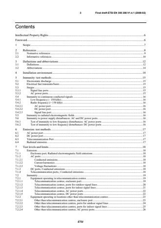
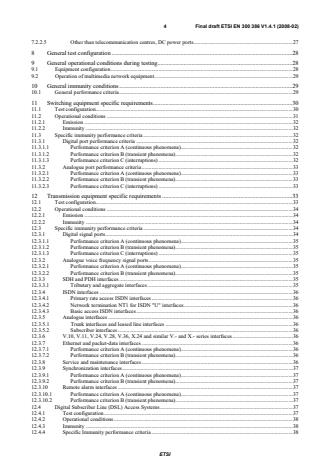
ETSI EN 300 386 V1.4.1 (2008-02) - Electromagnetic compatibility and Radio spectrum Matters (ERM); Telecommunication network equipment; ElectroMagnetic Compatibility (EMC) requirements
ETSI EN 300 386 V1.4.1 (2008-04) - Electromagnetic compatibility and Radio spectrum Matters (ERM); Telecommunication network equipment; ElectroMagnetic Compatibility (EMC) requirements

SIST EN 300 386 V1.4.1:2008 is a Harmonized European Standard for electromagnetic compatibility (EMC) requirements for telecommunication network equipment. It specifies the emission and immunity tests for non-radio equipment used in public telecommunications networks between Network Termination Points (NTPs), including switching, transmission, power supply, supervisory and multimedia network equipment. Engineers, buyers and test laboratories use it to choose the right test methods, levels and performance criteria for the ports and installation environment being assessed.
What does SIST EN 300 386 V1.4.1:2008 specify?
SIST EN 300 386 V1.4.1:2008 covers EMC requirements for non-radio equipment intended for public telecommunications networks, and it requires all available functions of the EUT to be tested. The scope includes switching equipment, non-radio transmission and ancillary equipment, power supply equipment and supervisory equipment.
The standard applies to equipment used in telecommunication centres and in locations other than telecommunication centres, using the environmental classes defined in TR 101 651. It excludes terminal equipment beyond the NTPs, equipment for cabled distribution systems intended only for television and sound signals, and optical amplifiers.
The document is organized into scope, references, definitions and abbreviations, installation environment, immunity test methods, emission test methods, test levels and limits, general test configuration, operational conditions, general immunity conditions, and equipment-specific clauses for switching, transmission, power supply and supervisory equipment.
| Annex | What it covers |
|---|---|
| Annex A | Normative surge test method for ports of signal lines remaining within a building |
| Annex B | Informative evaluation of test results and test report content |
| Annex C | Informative EMC guidance for RF ports of multimedia network equipment |
| Annex D | Informative title in the official languages |
| Annex E | Informative bibliography |
What are the key requirements of SIST EN 300 386 V1.4.1:2008?
SIST EN 300 386 V1.4.1:2008 ties EMC compliance to both the installation environment and the port type. In practice, the test plan must match where the equipment will be installed, which ports are permanently connected, and which functions of the EUT are actually in use.
Installation and test planning
Clause 4 separates the equipment into two environments: telecommunication centres and locations other than telecommunication centres. If the product documentation does not restrict the installation environment, the equipment is tested for all environments using the more severe level.
Clause 5 says conducted immunity is applied one port at a time, and only permanently connected signal ports are tested. One port of each type must be representative, and any test judged unnecessary must be justified in the test report. That matters because the report must show why a port was selected or excluded.
Emission and immunity methods
Clauses 5 and 6 define the main methods: electrostatic discharge, electrical fast transient/burst, surge, conducted RF immunity, radiated field immunity, and power supply disturbance tests. For emissions, the standard uses EN 55022 for AC, DC and telecommunication ports, EN 61000-3-2 or EN 61000-3-12 for current harmonics, and EN 61000-3-3 or EN 61000-3-11 for voltage fluctuations and flicker.
Clause 7 sets the actual levels. For radiated immunity, the table reaches 2 700 MHz and includes 3 V/m with 80% AM at 1 kHz in the lower and upper ranges shown in the standard. For enclosure ports, the ESD levels differ by environment, with higher levels outside telecommunication centres.
Performance criteria and equipment-specific behavior
Clause 10 defines the three performance criteria used throughout the document. Criterion A allows no degradation during exposure, criterion B allows limited temporary degradation during exposure but no lasting change, and criterion C allows temporary loss of function if the function recovers by itself or by normal use.
Clauses 11 to 14 add equipment-specific rules. Switching equipment must keep connections in place and, for analogue line interfaces, the document checks selected frequencies and noise levels at the port. Transmission equipment is tested with a suitable traffic pattern such as PRBS, while DSL access systems are tested at nominal rate and at the minimum acceptable noise margin. Power supply equipment and supervisory equipment have their own criteria for alarms, output behavior and recovery after exposure.
What terms does SIST EN 300 386 V1.4.1:2008 define?
- Equipment Under Test (EUT) - the item being evaluated during EMC testing.
- enclosure port - the physical boundary of the EUT where electromagnetic fields may leave or enter.
- performance criterion - the allowed behavior of the equipment during and after an EMC exposure.
- performance criterion A - the equipment continues to operate as intended during the test.
- performance criterion B - temporary degradation is allowed during exposure, but the equipment must recover after the test.
- performance criterion C - temporary loss of function is allowed if the function is self-recoverable or can be restored by normal operation.
- telecommunication network ports - ports intended for voice, data and signalling interconnection in telecom and similar networks.
- radio frequencies (RF) - the frequency range above 150 kHz.
Who uses SIST EN 300 386 V1.4.1:2008?
Manufacturers of telecommunication network equipment use SIST EN 300 386 V1.4.1:2008 to design EMC testing and to write product documentation that matches the intended installation environment. EMC test laboratories use it to configure the EUT, select ports, and record test results against the correct performance criterion.
Network operators, system integrators, quality managers and buyers use it when assessing switching equipment, transmission systems, power supplies, supervisory equipment and DSL access systems for public telecommunications networks. It is also relevant when one product combines several functions, because the standard requires all available functions to be considered.
What changed in SIST EN 300 386 V1.4.1:2008 from the previous edition?
The 2008 version updates references to CISPR 16-1, EN 50082-1, EN 55022, EN 61000-4-2, EN 61000-4-3, EN 61000-4-4, EN 61000-4-5, EN 61000-4-6, EN 61000-4-11 and EN 300 132-2, and it adds dates to the basic standards. It also adds EN 61000-3-11 and EN 61000-3-12, extends radiated immunity into the 2 GHz to 2.7 GHz range with a 3 V/m level and 80% AM at 1 kHz, updates the AC-port voltage dips and short interruptions test for locations other than telecommunication centres, removes ETR 238 from the bibliography, and adds normative Annex A.
Which standards are used with SIST EN 300 386 V1.4.1:2008?
SIST EN 300 386 V1.4.1:2008 relies on EN 55016-1-2 for conducted disturbance measurement apparatus and the artificial network used on DC ports. It uses EN 55022 for conducted and radiated emissions, EN 61000-4-2/-3/-4/-5/-6/-11 for the main immunity test methods, and EN 61000-3-2/-3/-11/-12 for harmonics and flicker on AC ports.
EN 300 132-1 and EN 300 132-2 define the AC and DC secondary interface conditions used in the power supply clauses. TR 101 651 defines the environmental classes, EN 300 127 supports radiated emission testing for physically large equipment, and ITU-T O.41 is used for psophometric noise measurement on the DC secondary interface. The interface and service references, including EN 300 011-1, ETS 300 012-1, EN 300 166, ETS 300 232, G.783, G.798, G.712, Q.552, V-series and X-series recommendations, G.812, G.813 and the DSL references, identify the port families and operating modes covered by the equipment-specific clauses.
What does the SIST EN 300 386 V1.4.1:2008 document contain?
Clause 7 compiles the emission limits and immunity levels in tables for each port type and installation environment. Clauses 11 to 14 give the special configurations and performance criteria for switching equipment, transmission equipment, DSL access systems, power supply equipment and supervisory equipment.
Annex A provides a dedicated surge test setup for signal-line ports remaining within a building, including the pulse generator and impedance matching arrangement. Annex B tells the test lab what to record in the report, while Annex C explains extra EMC guidance for RF ports in multimedia network equipment. Figures 1 to 6 and A.1 to A.2 illustrate the required test configurations.
Relations
- Official Journal Project Relation
SIST EN 300 386 V1.3.3:2006 - Electromagnetic compatibility and Radio spectrum Matters (ERM); Telecommunication network equipment; ElectroMagnetic Compatibility (EMC) requirements - Effective Date
- 05-Jun-2009
Buy Documents
ETSI EN 300 386 V1.4.1 (2008-02) - Electromagnetic compatibility and Radio spectrum Matters (ERM); Telecommunication network equipment; ElectroMagnetic Compatibility (EMC) requirements
ETSI EN 300 386 V1.4.1 (2008-04) - Electromagnetic compatibility and Radio spectrum Matters (ERM); Telecommunication network equipment; ElectroMagnetic Compatibility (EMC) requirements
Get Certified
Connect with accredited certification bodies for this standard

ANCE
Mexican certification and testing association.

Intertek Slovenia
Intertek testing, inspection, and certification services in Slovenia.

LNE (Laboratoire National de Métrologie et d'Essais)
French national laboratory for metrology and testing.
Sponsored listings
Frequently Asked Questions
SIST EN 300 386 V1.4.1:2008 is a standard published by the Slovenian Institute for Standardization (SIST). Its full title is "Electromagnetic compatibility and Radio spectrum Matters (ERM) - Telecommunication network equipment - ElectroMagnetic Compatibility (EMC) requirements". This standard covers: update the references of CISPR 16-1, EN50082-1, EN55022, EN61000-4-2, EN61000-4-3, EN61000-4-4, EN61000-4-5, EN61000-4-6, EN61000-4-11 and EN300132-2 and add dates to the basic standards include the reference of EN61000-3-11 and EN61000-3-12 include radiated immunity test (sub-clause 7.2.1.1.2 and 7.2.2.1.2) in the frequency range 2-2.7GHz; test level 3V/m; 80% AM at 1kHz; performance criterion A update the vvoltage dips and short interruption tests on AC port of Other than Telecommunication centre (sub-clause 7.2.2.4.4) according to the latest publication of EN61000-4-11 and the generic standard IEC61000-6-2 remove the ETR238 from the bibliography add the normative Annex A as in EN301489-1 under revision process
update the references of CISPR 16-1, EN50082-1, EN55022, EN61000-4-2, EN61000-4-3, EN61000-4-4, EN61000-4-5, EN61000-4-6, EN61000-4-11 and EN300132-2 and add dates to the basic standards include the reference of EN61000-3-11 and EN61000-3-12 include radiated immunity test (sub-clause 7.2.1.1.2 and 7.2.2.1.2) in the frequency range 2-2.7GHz; test level 3V/m; 80% AM at 1kHz; performance criterion A update the vvoltage dips and short interruption tests on AC port of Other than Telecommunication centre (sub-clause 7.2.2.4.4) according to the latest publication of EN61000-4-11 and the generic standard IEC61000-6-2 remove the ETR238 from the bibliography add the normative Annex A as in EN301489-1 under revision process
SIST EN 300 386 V1.4.1:2008 is classified under the following ICS (International Classification for Standards) categories: 33.050.01 - Telecommunication terminal equipment in general; 33.100.01 - Electromagnetic compatibility in general. The ICS classification helps identify the subject area and facilitates finding related standards.
SIST EN 300 386 V1.4.1:2008 has the following relationships with other standards: It is inter standard links to SIST EN 300 386 V1.3.3:2006. Understanding these relationships helps ensure you are using the most current and applicable version of the standard.
SIST EN 300 386 V1.4.1:2008 is associated with the following European legislation: EU Directives/Regulations: 2004/108/EU; Standardization Mandates: T-353. When a standard is cited in the Official Journal of the European Union, products manufactured in conformity with it benefit from a presumption of conformity with the essential requirements of the corresponding EU directive or regulation.
SIST EN 300 386 V1.4.1:2008 is available in PDF format for immediate download after purchase. The document can be added to your cart and obtained through the secure checkout process. Digital delivery ensures instant access to the complete standard document.
Standards Content (Sample)
Final draft ETSI EN 300 386 V1.4.1 (2008-02)
Harmonized European Standard (Telecommunications series)
Electromagnetic compatibility
and Radio spectrum Matters (ERM);
Telecommunication network equipment;
ElectroMagnetic Compatibility (EMC) requirements
2 Final draft ETSI EN 300 386 V1.4.1 (2008-02)
Reference
REN/ERM-EMC-249
Keywords
EMC, network, testing
ETSI
650 Route des Lucioles
F-06921 Sophia Antipolis Cedex - FRANCE
Tel.: +33 4 92 94 42 00 Fax: +33 4 93 65 47 16
Siret N° 348 623 562 00017 - NAF 742 C
Association à but non lucratif enregistrée à la
Sous-Préfecture de Grasse (06) N° 7803/88
Important notice
Individual copies of the present document can be downloaded from:
http://www.etsi.org
The present document may be made available in more than one electronic version or in print. In any case of existing or
perceived difference in contents between such versions, the reference version is the Portable Document Format (PDF).
In case of dispute, the reference shall be the printing on ETSI printers of the PDF version kept on a specific network drive
within ETSI Secretariat.
Users of the present document should be aware that the document may be subject to revision or change of status.
Information on the current status of this and other ETSI documents is available at
http://portal.etsi.org/tb/status/status.asp
If you find errors in the present document, please send your comment to one of the following services:
http://portal.etsi.org/chaircor/ETSI_support.asp
Copyright Notification
No part may be reproduced except as authorized by written permission.
The copyright and the foregoing restriction extend to reproduction in all media.
© European Telecommunications Standards Institute 2008.
All rights reserved.
TM TM TM TM
DECT , PLUGTESTS , UMTS , TIPHON , the TIPHON logo and the ETSI logo are Trade Marks of ETSI registered
for the benefit of its Members.
TM
3GPP is a Trade Mark of ETSI registered for the benefit of its Members and of the 3GPP Organizational Partners.
ETSI
3 Final draft ETSI EN 300 386 V1.4.1 (2008-02)
Contents
Intellectual Property Rights.6
Foreword.6
1 Scope.7
2 References.8
2.1 Normative references.9
2.2 Informative references.10
3 Definitions and abbreviations.12
3.1 Definitions.12
3.2 Abbreviations.14
4 Installation environment.14
5 Immunity: test methods.15
5.1 Electrostatic discharge.15
5.2 Electrical fast transients/burst.15
5.3 Surges.15
5.3.1 Signal line ports .15
5.3.2 AC power ports.15
5.4 Immunity to continuous conducted signals .16
5.4.1 Low frequency ( ≤ 150 kHz).16
5.4.2 Radio frequency (> 150 kHz) .16
5.4.2.1 AC power port.16
5.4.2.2 DC power port.16
5.4.2.3 Signal line port.16
5.5 Immunity to radiated electromagnetic fields .16
5.6 Immunity to power supply disturbances: AC and DC power ports.16
5.6.1 Test of immunity to low frequency disturbances: AC power ports .16
5.6.2 Test of immunity to low frequency disturbances: DC power ports .16
6 Emission: test methods.17
6.1 AC power port.17
6.2 DC power port.17
6.3 Telecommunication Port.17
6.4 Radiated emission.17
7 Test levels and limits.18
7.1 Emission.18
7.1.1 Enclosure port, Radiated electromagnetic field emissions.18
7.1.2 AC ports.18
7.1.2.1 Conducted emissions.18
7.1.2.2 Current harmonics.18
7.1.2.3 Voltage fluctuations.18
7.1.3 DC ports, Conducted emissions.18
7.1.4 Telecommunication ports,; Conducted emissions.18
7.2 Immunity.19
7.2.1 Equipment operating in telecommunication centres .19
7.2.1.1 Telecommunication centres, enclosure port.19
7.2.1.2 Telecommunication centres, ports for outdoor signal lines.20
7.2.1.3 Telecommunication centres, ports for indoor signal lines.21
7.2.1.4 Telecommunication centres, AC power ports .22
7.2.1.5 Telecommunication centres, DC power ports .22
7.2.2 Equipment operating in locations other than telecommunication centres.23
7.2.2.1 Other than telecommunication centres, enclosure port .23
7.2.2.2 Other than telecommunication centres, ports for outdoor signal lines .24
7.2.2.3 Other than telecommunication centres, ports for indoor signal lines .25
7.2.2.4 Other than telecommunication centres, AC power ports.26
ETSI
4 Final draft ETSI EN 300 386 V1.4.1 (2008-02)
7.2.2.5 Other than telecommunication centres, DC power ports.27
8 General test configuration .28
9 General operational conditions during testing.28
9.1 Equipment configuration.28
9.2 Operation of multimedia network equipment.29
10 General immunity conditions .29
10.1 General performance criteria.29
11 Switching equipment specific requirements.30
11.1 Test configuration.30
11.2 Operational conditions.31
11.2.1 Emission.32
11.2.2 Immunity.32
11.3 Specific immunity performance criteria.32
11.3.1 Digital port performance criteria .32
11.3.1.1 Performance criterion A (continuous phenomena).32
11.3.1.2 Performance criterion B (transient phenomena).32
11.3.1.3 Performance criterion C (interruptions) .32
11.3.2 Analogue port performance criteria .33
11.3.2.1 Performance criterion A (continuous phenomena).33
11.3.2.2 Performance criterion B (transient phenomena).33
11.3.2.3 Performance criterion C (interruptions) .33
12 Transmission equipment specific requirements .33
12.1 Test configuration.33
12.2 Operational conditions.34
12.2.1 Emission.34
12.2.2 Immunity.34
12.3 Specific immunity performance criteria.34
12.3.1 Digital signal ports.34
12.3.1.1 Performance criterion A (continuous phenomena).35
12.3.1.2 Performance criterion B (transient phenomena).35
12.3.1.3 Performance criterion C (interruptions) .35
12.3.2 Analogue voice frequency signal ports.35
12.3.2.1 Performance criterion A (continuous phenomena).35
12.3.2.2 Performance criterion B (transient phenomena).35
12.3.3 SDH and PDH interfaces .35
12.3.3.1 Tributary and aggregate interfaces.35
12.3.4 ISDN interfaces.36
12.3.4.1 Primary rate access ISDN interfaces.36
12.3.4.2 Network termination NT1 for ISDN "U" interfaces.36
12.3.4.3 Basic access ISDN interfaces.36
12.3.5 Analogue interfaces.36
12.3.5.1 Trunk interfaces and leased line interfaces .36
12.3.5.2 Subscriber interfaces.36
12.3.6 V.10, V.11, V.24, V.28, V.36, X.24 and similar V.- and X.- series interfaces .36
12.3.7 Ethernet and packet-data interfaces .36
12.3.7.1 Performance criterion A (continuous phenomena).36
12.3.7.2 Performance criterion B (transient phenomena).36
12.3.8 Service and maintenance interfaces .36
12.3.9 Synchronization interfaces.37
12.3.9.1 Performance criterion A (continuous phenomena).37
12.3.9.2 Performance criterion B (transient phenomena).37
12.3.10 Remote alarm interfaces .37
12.3.10.1 Performance criterion A (continuous phenomena).37
12.3.10.2 Performance criterion B (transient phenomena).37
12.4 Digital Subscriber Line (DSL) Access Systems.37
12.4.1 Test configuration.37
12.4.2 Operational conditions.38
12.4.3 Immunity.38
12.4.4 Specific Immunity performance criteria .38
ETSI
5 Final draft ETSI EN 300 386 V1.4.1 (2008-02)
12.4.4.1 Performance Criteria A (continuous phenomena).39
12.4.4.2 Performance Criteria B (transient phenomena).39
12.4.4.3 Performance Criteria C (interruptions).39
13 Power supply equipment specific conditions .39
13.1 Test configuration.39
13.2 Operational conditions.40
13.2.1 Emission.40
13.2.2 Immunity.40
13.3 Specific immunity performance criteria.41
13.3.1 Alternating current secondary interface.41
13.3.1.1 Performance criterion A (continuous phenomena).41
13.3.1.2 Performance criterion B (transient phenomena).41
13.3.2 Direct current secondary interface .42
13.3.2.1 Performance criterion A (continuous phenomena).42
13.3.2.2 Performance criterion B (transient phenomena).42
13.3.3 Control/signal interface.42
13.3.4 Tertiary supply interface.42
14 Supervisory equipment specific conditions.42
14.1 Test configuration.42
14.2 Operational conditions.43
14.3 Specific immunity performance criteria.43
14.3.1 Performance criterion A (continuous phenomena) .43
14.3.2 Performance criterion B (transient phenomena) .43
Annex A (normative): Surges: test method for ports of signal lines remaining within the
building .44
A.1 Test set-up for signal ports .44
Annex B (informative): Evaluation of test results .46
Annex C (informative): Guidance on EMC performance requirements and methods of
measurement for RF ports (in the sense of EN 50083 series) of
multimedia network equipment .48
Annex D (informative): The EN title in the official languages .49
Annex E (informative): Bibliography.50
History .51
ETSI
6 Final draft ETSI EN 300 386 V1.4.1 (2008-02)
Intellectual Property Rights
IPRs essential or potentially essential to the present document may have been declared to ETSI. The information
pertaining to these essential IPRs, if any, is publicly available for ETSI members and non-members, and can be found
in ETSI SR 000 314: "Intellectual Property Rights (IPRs); Essential, or potentially Essential, IPRs notified to ETSI in
respect of ETSI standards", which is available from the ETSI Secretariat. Latest updates are available on the ETSI Web
server (http://webapp.etsi.org/IPR/home.asp).
Pursuant to the ETSI IPR Policy, no investigation, including IPR searches, has been carried out by ETSI. No guarantee
can be given as to the existence of other IPRs not referenced in ETSI SR 000 314 (or the updates on the ETSI Web
server) which are, or may be, or may become, essential to the present document.
Foreword
This Harmonized European Standard (Telecommunications series) has been produced by ETSI Technical Committee
Electromagnetic compatibility and Radio spectrum Matters (ERM), and is now submitted for the Vote phase of the
ETSI standards Two-step Approval Procedure.
The present document has been produced by ETSI in response to a mandate from the European Commission issued
under Council Directive 98/34/EC [51] (as amended) laying down a procedure for the provision of information in the
field of technical standards and regulations.
The present document is intended to become a Harmonized Standard, the reference of which will be published in the
Official Journal of the European Communities referencing the Council Directive on the approximation of the laws of
the Member States relating to electromagnetic compatibility ("the EMC Directive") (89/336/EEC [49] as amended and
2004/108/EC [52]).
Proposed national transposition dates
Date of latest announcement of this EN (doa): 3 months after ETSI publication
Date of latest publication of new National Standard
or endorsement of this EN (dop/e): 6 months after doa
Date of withdrawal of any conflicting National Standard (dow): 36 months after doa
ETSI
7 Final draft ETSI EN 300 386 V1.4.1 (2008-02)
1 Scope
The present document covers the EMC requirements for non-radio equipment intended to be used within a public
telecommunications network, which provides telecommunications between Network Termination Points (NTPs)
(i.e. excluding terminal equipment beyond the NTPs). Examples of such equipment are:
• Switching equipment. Such equipment includes:
- local telephone exchanges;
- remote switching concentrators;
- international switches;
- telex switches;
- network packet switches;
- base station controllers, radio network controllers;
- network servers and gateways.
• Non-radio transmission equipment and ancillary equipment. Such equipment includes:
- multiplexers;
- line equipment and repeaters, e.g. equipment for:
Synchronous Digital Hierarchy (SDH);
Plesiochronous Digital Hierarchy (PDH);
Asynchronous Transfer Mode (ATM);
such as:
Digital Cross Connect systems;
network terminations;
transmission equipment used in the access network like XDSL.
• Power supply equipment. Such equipment includes:
- central power plant;
- end of suite power supplies;
- uninterruptible power supplies;
- stabilized AC power supplies; and
- other dedicated telecommunication network power supplies;
but excludes equipment which is uniquely associated with or integrated in other equipment.
ETSI
8 Final draft ETSI EN 300 386 V1.4.1 (2008-02)
• Supervisory equipment. Such equipment includes:
- network management equipment;
- operator access maintenance equipment;
- traffic measurement systems;
- line test units;
- functional test units.
The function of supervision may either be performed by independent equipment or form part of other
telecommunication network equipment. If the function of supervision forms part of a telecommunication network
equipment, the performance may be evaluated simultaneously with other functions (such as switching and transmission)
during EMC testing.
The environmental classification locations used in the present document refers to TR 101 651 [50].
The requirements of the present document have been selected to ensure an adequate level of immunity for the apparatus
covered by the scope of the present document. The levels do not, however, cover extreme cases which may occur at any
location but with a low probability of occurrence. In special cases, situations may arise where the levels of disturbance
may exceed the immunity test levels specified in the present document. In these instances, special mitigation measures
may have to be employed.
General purpose equipment, which is used as a part of a telecommunication network, may be covered by the scope of
other standards. For such equipment, if those other standards fully cover the requirements of the present document, no
further assessment is necessary. Equipment for cabled distribution systems intended only for television and sound
signals as defined in EN 50083-2 [3] and optical amplifiers as defined in ITU-T Recommendations G.661 [33] and
G.662 [34] are outside the scope of the present document.
Equipment may provide different functions, i.e. switching equipment may also provide transmission functions and
transmission equipment may provide storage capabilities etc. All available functions of the EUT shall be tested.
2 References
References are either specific (identified by date of publication and/or edition number or version number) or
non-specific.
• For a specific reference, subsequent revisions do not apply.
• Non-specific reference may be made only to a complete document or a part thereof and only in the following
cases:
- if it is accepted that it will be possible to use all future changes of the referenced document for the
purposes of the referring document;
- for informative references.
Referenced documents which are not found to be publicly available in the expected location might be found at
http://docbox.etsi.org/Reference.
For online referenced documents, information sufficient to identify and locate the source shall be provided. Preferably,
the primary source of the referenced document should be cited, in order to ensure traceability. Furthermore, the
reference should, as far as possible, remain valid for the expected life of the document. The reference shall include the
method of access to the referenced document and the full network address, with the same punctuation and use of upper
case and lower case letters.
NOTE: While any hyperlinks included in this clause were valid at the time of publication ETSI cannot guarantee
their long term validity.
ETSI
9 Final draft ETSI EN 300 386 V1.4.1 (2008-02)
2.1 Normative references
The following referenced documents are indispensable for the application of the present document. For dated
references, only the edition cited applies. For non-specific references, the latest edition of the referenced document
(including any amendments) applies.
[1] CENELEC EN 55016-1-2 ((Amendment - 2006): "Specification for radio disturbance and
immunity measuring apparatus and methods -- Part 1-2: Radio disturbance and immunity
measuring apparatus - Ancillary equipment - Conducted disturbances".
[2] Void.
[3] CENELEC EN 50083-2 (2006): "Cable networks for television signals, sound signals and
interactive services -- Part 2: Electromagnetic compatibility for equipment".
[4] CENELEC EN 55022 (2006): "Information technology equipment - Radio disturbance
characteristics - Limits and methods of measurement".
[5] CENELEC EN 61000-3-2 (2006): "Electromagnetic compatibility (EMC) -- Part 3-2: Limits -
Limits for harmonic current emissions (equipment input current <= 16 A per phase)".
[6] CENELEC EN 61000-3-3 (1995): "Electromagnetic compatibility (EMC) -- Part 3-3: Limits -
Limitation of voltage changes, voltage fluctuations and flicker in public low-voltage supply
systems, for equipment with rated current <= 16 A per phase and not subject to conditional
connection".
[7] CENELEC EN 61000-3-11 (2000): "Electromagnetic compatibility (EMC) -- Part 3-11: Limits -
Limitation of voltage changes, voltage fluctuations and flicker in public low-voltage supply
systems - Equipment with rated current <= 75 A and subject to conditional connection".
[8] CENELEC EN 61000-3-12 (2005): "Electromagnetic compatibility (EMC) -- Part 3-12: Limits -
Limits for harmonic currents produced by equipment connected to public low-voltage systems
with input current > 16 A and <= 75 A per phase".
[9] CENELEC EN 61000-4-2 (2001): "Electromagnetic compatibility (EMC) -- Part 4-2: Testing and
measurement techniques - Electrostatic discharge immunity test".
[10] CENELEC EN 61000-4-3 (2006): "Electromagnetic compatibility (EMC) -- Part 4-3: Testing and
measurement techniques - Radiated, radio-frequency, electromagnetic field immunity test".
[11] CENELEC EN 61000-4-4 (2004): "Electromagnetic compatibility (EMC) -- Part 4-4: Testing and
measurement techniques - Electrical fast transient/burst immunity test".
[12] CENELEC EN 61000-4-5 (2006): "Electromagnetic compatibility (EMC) -- Part 4-5: Testing and
measurement techniques - Surge immunity test".
[13] CENELEC EN 61000-4-6 (2006): "Electromagnetic compatibility (EMC) -- Part 4-6: Testing and
measurement techniques - Immunity to conducted disturbances, induced by radio-frequency
fields".
[14] CENELEC EN 61000-4-11 (2004): "Electromagnetic compatibility (EMC) -- Part 4-11: Testing
and measurement techniques - Voltage dips, short interruptions and voltage variations immunity
tests".
[15] ETSI ETS 300 132-1 (1996): "Equipment Engineering (EE); Power supply interface at the input to
telecommunications equipment; Part 1: Operated by alternating current (ac) derived from direct
current (dc) sources".
[16] ETSI EN 300 132-2 (V2.1.2): "Environmental Engineering (EE); Power supply interface at the
input to telecommunications equipment; Part 2: Operated by direct current (dc)".
[17] IEC 60050-161: "International Electrotechnical Vocabulary. Chapter 161: Electromagnetic
compatibility".
ETSI
10 Final draft ETSI EN 300 386 V1.4.1 (2008-02)
[18] IEC 60050-714: "International Electrotechnical Vocabulary - Chapter 714: Switching and
signalling in telecommunications".
[19] ETSI EN 300 127 (V1.2.1): "Electromagnetic compatibility and Radio spectrum Matters (ERM);
Radiated emission testing of physically large telecommunication systems".
[20] ITU-T Recommendation O.41 (1994): "Psophometer for use on telephone-type circuits".
[21] ITU-T Recommendation G.996.1 (2001): "Test procedures for digital subscriber line (DSL)
transceivers".
[22] ETSI TS 101 135 (V1.5.3): "Transmission and Multiplexing (TM); High bit-rate Digital
Subscriber Line (HDSL) transmission systems on metallic local lines; HDSL core specification
and applications for combined ISDN-BA and 2 048 kbit/s transmission".
[23] ETSI TS 101 524-1 (V1.1.1): "Transmission and Multiplexing (TM); Access transmission system
on metallic access cables; Symmetrical single pair high bit rate Digital Subscriber Line (SDSL);
Part 1: Functional requirements".
[24] ETSI TS 101 270-1 (V1.4.1): "Transmission and Multiplexing (TM); Access transmission systems
on metallic access cables; Very high speed Digital Subscriber Line (VDSL); Part 1: Functional
requirements".
[25] ITU-T Recommendation G.992.1 (2003): "Asymmetrical digital subscriber line (ADSL)
transceivers".
[26] ITU-T Recommendation G.992.3 (2006): " Asymmetrical digital subscriber line transceivers 2
(ADSL2)".
[27] ITU-T Recommendation G.992.5 (2006): "Asymmetrical Digital Subscriber Line (ADSL)
transceivers - Extended bandwidth ADSL2 (ADSL2plus)".
2.2 Informative references
[28] ETSI EN 300 011-1 (V1.2.2): "Integrated Services Digital Network (ISDN); Primary rate User
Network Interface (UNI); Part 1: Layer 1 specification".
[29] ETSI ETS 300 012-1 (2000): "Integrated Services Digital Network (ISDN); Basic User-Network
Interface (UNI); Part 1: Layer 1 specification".
[30] ETSI EN 300 166 (V1.2.1): "Transmission and Multiplexing (TM); Physical and electrical
characteristics of hierarchical digital interfaces for equipment using the 2 048 kbit/s - based
plesiochronous or synchronous digital hierarchies".
[31] ETSI ETS 300 232 (1993): "Transmission and Multiplexing (TM); Optical interfaces for
equipments and systems relating to the Synchronous Digital Hierarchy [ITU-T Recommendation
G.957 (1993), modified]".
[32] ISO/IEC 8802-3 (2000): "Information technology - Telecommunications and information
exchange between systems - Local and metropolitan area networks - Specific requirements -
Part 3: Carrier sense multiple access with collision detection (CSMA/CD) access method and
physical layer specifications".
[33] ITU-T Recommendation G.661 (2006): "Definition and test methods for the relevant generic
parameters of optical amplifier devices and subsystems".
[34] ITU-T Recommendation G.662 (2005): "Generic characteristics of optical amplifier devices and
subsystems".
[35] ITU-T Recommendation G.712 (2001): "Transmission performance characteristics of pulse code
modulation channels".
[36] ITU-T Recommendation G.812 (2004): "Timing requirements of slave clocks suitable for use as
node clocks in synchronization networks".
ETSI
11 Final draft ETSI EN 300 386 V1.4.1 (2008-02)
[37] ITU-T Recommendation G.813 (2003): "Timing characteristics of SDH equipment slave clocks
(SEC)".
[38] Void.
[39] ITU-T Recommendation G.961 (1993): "Digital transmission system on metallic local lines for
ISDN basic rate access".
[40] ITU-T Recommendation O.150 (1996): "General requirements for instrumentation for
performance measurements on digital transmission equipment".
[41] ITU-T Recommendation Q.552 (2001): "Transmission characteristics at 2-wire analogue interfaces
of digital exchanges".
[42] ITU-T Recommendation V.10 (1993): "Electrical characteristics for unbalanced double-current
interchange circuits operating at data signalling rates nominally up to 100 kbit/s".
[43] ITU-T Recommendation V.11 (1996): "Electrical characteristics for balanced double-current
interchange circuits operating at data signalling rates up to 10 Mbit/s".
[44] ITU-T Recommendation V.24 (2000): "List of definitions for interchange circuits between Data
Terminal Equipment (DTE) and Data Circuit-terminating Equipment (DCE)".
[45] ITU-T Recommendation V.28 (1993): "Electrical characteristics for unbalanced double-current
interchange circuits".
[46] ITU-T Recommendation V.36 (1988): "Modems for synchronous data transmission using
60-108 kHz group band circuits".
[47] ITU-T Recommendation X.24 (1988): "List of definitions for interchange circuits between Data
Terminal Equipment (DTE) and Data Circuit-terminating Equipment (DCE) on public data
networks".
[48] ITU-T Recommendation X.25 (1996): "Interface between Data Terminal Equipment (DTE) and
Data Circuit-terminating Equipment (DCE) for terminals operating in the packet mode and
connected to public data networks by dedicated circuit".
[49] Council Directive 89/336/EEC of 3 May 1989 on the approximation of the laws of the Member
States relating to electromagnetic compatibility.
[50] ETSI TR 101 651 (1999): "Electromagnetic compatibility and radio spectrum matters (ERM);
Classification of the electromagnetic environment conditions for equipment in telecommunication
networks".
[51] Directive 98/34/EC of the European Parliament and of the Council of 22 June 1998 laying down a
procedure for the provision of information in the field of technical standards and regulations (EMC
Directive).
[52] Council Directive 2004/108/EC of 15 December 2004 on the approximation of the laws of the
Member States relating to electromagnetic compatibility and repealing Directive 89/336/EEC
(EMC Directive).
[53] ITU-T Recommendation G.783 (2006): "Characteristics of synchronous digital hierarchy (SDH)
equipment functional blocks".
[54] ITU-T Recommendation G.798 (2004): "Characteristics of optical transport network hierarchy
equipment functional blocks".
[55] Directive 1999/5/EC of the European Parliament and of the Council of 9 March 1999 on radio
equipment and telecommunications terminal equipment and the mutual recognition of their
conformity (R&TTE Directive).
[56] IEEE 1284 (2000): "IEEE Standard Signalling Method for a Bidirectional Parallel Peripheral
Interface for Personal Computers".
[57] IEEE 1394.1 (2004): "IEEE Standard for High Performance Serial Bus Bridges".
ETSI
12 Final draft ETSI EN 300 386 V1.4.1 (2008-02)
3 Definitions and abbreviations
3.1 Definitions
For the purposes of the present document, the terms and definitions given in IEC 60050-161 [17] and the following
apply:
NOTE: The definitions taken from IEC 60050-161 [17] have reference in parentheses.
AC secondary interface: output port of an AC power supply
AC secondary voltage: output of the AC power supply at the AC secondary interface
NOTE: The AC secondary voltage may be either:
a stabilized AC supply derived from a DC primary supply (e.g. where the power supply is an
inverter); or
derived from the AC primary supply (e.g. a stabilized power supply used where the quality of the
primary supply is not sufficient to feed telecommunication equipment).
burst (161-02-07): sequence of a limited number of distinct pulses or an oscillation of limited duration
connection: temporary association of transmission channels or telecommunication circuits, switching or other
functional units set up to provide for the transfer of information between two or more points in a telecommunication
network (IEC 60050-714 [18])
continuous disturbance (161-02-11): electromagnetic disturbance the effects of which on a particular device or
equipment cannot be resolved into a succession of distinct effects
DC secondary interface: output port of a DC power supply
DC secondary voltage: output of the DC power supply at the DC secondary interface
NOTE: The DC secondary voltage may be derived from the AC primary supply with or without a buffer battery.
duration (of a voltage change) (161-08-03): interval of time for the voltage to increase or decrease from the initial
value to the final value
duration (of a pulse): interval of time between the instants at which the instantaneous value of a pulse reaches 50 % of
the pulse magnitude for the first and last time
enclosure port: physical boundary of the Equipment Under Test (EUT) through which electromagnetic fields may
emanate or on which they may impinge
environment, environmental conditions: electromagnetic conditions external to the equipment, to which it is
subjected at a certain time
NOTE: The environmental conditions comprise a combination of single environmental parameters and their
severity.
environmental parameters: present one or more properties of the electromagnetic environment
immunity (to a disturbance) (161-01-20): ability of a device, equipment or system to perform without degradation in
the presence of an electromagnetic disturbance
impulsive disturbance (161-02-09): electromagnetic disturbance which, when incident on a particular device or
equipment, manifests itself as a succession of distinct pulses or transients
interface "A": terminals at which a power supply is connected to the telecommunications equipment
multimedia network equipment: multimedia network equipment containing broadcast and telecommunication
functions
ETSI
13 Final draft ETSI EN 300 386 V1.4.1 (2008-02)
nominal voltage: nominal value of voltage that designates the type of supply
normal service: service mode where telecommunications equipment operates within its specification
performance criterion: limits of acceptable behaviour of the equipment during and after the application of the
electromagnetic phenomenon
NOTE: Performance criteria A apply for continuous phenomena; performance criteria B and C apply for transient
phenomena; and performance criteria R apply for resistibility phenomena.
port: particular interface of the EUT with the external electromagnetic environment
power supply: power source (within the scope of the present document) to which telecommunications equipment is
intended to be connected
primary supply: public mains or a locally generated AC or DC supply
...
Harmonized European Standard (Telecommunications series)
Electromagnetic compatibility
and Radio spectrum Matters (ERM);
Telecommunication network equipment;
ElectroMagnetic Compatibility (EMC) requirements
2 ETSI EN 300 386 V1.4.1 (2008-04)
Reference
REN/ERM-EMC-249
Keywords
EMC, network, testing
ETSI
650 Route des Lucioles
F-06921 Sophia Antipolis Cedex - FRANCE
Tel.: +33 4 92 94 42 00 Fax: +33 4 93 65 47 16
Siret N° 348 623 562 00017 - NAF 742 C
Association à but non lucratif enregistrée à la
Sous-Préfecture de Grasse (06) N° 7803/88
Important notice
Individual copies of the present document can be downloaded from:
http://www.etsi.org
The present document may be made available in more than one electronic version or in print. In any case of existing or
perceived difference in contents between such versions, the reference version is the Portable Document Format (PDF).
In case of dispute, the reference shall be the printing on ETSI printers of the PDF version kept on a specific network drive
within ETSI Secretariat.
Users of the present document should be aware that the document may be subject to revision or change of status.
Information on the current status of this and other ETSI documents is available at
http://portal.etsi.org/tb/status/status.asp
If you find errors in the present document, please send your comment to one of the following services:
http://portal.etsi.org/chaircor/ETSI_support.asp
Copyright Notification
No part may be reproduced except as authorized by written permission.
The copyright and the foregoing restriction extend to reproduction in all media.
© European Telecommunications Standards Institute 2008.
All rights reserved.
TM TM TM TM
DECT , PLUGTESTS , UMTS , TIPHON , the TIPHON logo and the ETSI logo are Trade Marks of ETSI registered
for the benefit of its Members.
TM
3GPP is a Trade Mark of ETSI registered for the benefit of its Members and of the 3GPP Organizational Partners.
ETSI
3 ETSI EN 300 386 V1.4.1 (2008-04)
Contents
Intellectual Property Rights.6
Foreword.6
1 Scope.7
2 References.8
2.1 Normative references.9
2.2 Informative references.10
3 Definitions and abbreviations.12
3.1 Definitions.12
3.2 Abbreviations.14
4 Installation environment.14
5 Immunity: test methods.15
5.1 Electrostatic discharge.15
5.2 Electrical fast transients/burst.15
5.3 Surges.15
5.3.1 Signal line ports .15
5.3.2 AC power ports.15
5.4 Immunity to continuous conducted signals .16
5.4.1 Low frequency ( ≤ 150 kHz).16
5.4.2 Radio frequency (> 150 kHz) .16
5.4.2.1 AC power port.16
5.4.2.2 DC power port.16
5.4.2.3 Signal line port.16
5.5 Immunity to radiated electromagnetic fields .16
5.6 Immunity to power supply disturbances: AC and DC power ports.16
5.6.1 Test of immunity to low frequency disturbances: AC power ports .16
5.6.2 Test of immunity to low frequency disturbances: DC power ports .16
6 Emission: test methods.17
6.1 AC power port.17
6.2 DC power port.17
6.3 Telecommunication Port.17
6.4 Radiated emission.17
7 Test levels and limits.18
7.1 Emission.18
7.1.1 Enclosure port, Radiated electromagnetic field emissions.18
7.1.2 AC ports.18
7.1.2.1 Conducted emissions.18
7.1.2.2 Current harmonics.18
7.1.2.3 Voltage fluctuations.18
7.1.3 DC ports, Conducted emissions.18
7.1.4 Telecommunication ports,; Conducted emissions.18
7.2 Immunity.19
7.2.1 Equipment operating in telecommunication centres .19
7.2.1.1 Telecommunication centres, enclosure port.19
7.2.1.2 Telecommunication centres, ports for outdoor signal lines.20
7.2.1.3 Telecommunication centres, ports for indoor signal lines.21
7.2.1.4 Telecommunication centres, AC power ports .22
7.2.1.5 Telecommunication centres, DC power ports .22
7.2.2 Equipment operating in locations other than telecommunication centres.23
7.2.2.1 Other than telecommunication centres, enclosure port .23
7.2.2.2 Other than telecommunication centres, ports for outdoor signal lines .24
7.2.2.3 Other than telecommunication centres, ports for indoor signal lines .25
7.2.2.4 Other than telecommunication centres, AC power ports.26
ETSI
4 ETSI EN 300 386 V1.4.1 (2008-04)
7.2.2.5 Other than telecommunication centres, DC power ports.27
8 General test configuration .28
9 General operational conditions during testing.28
9.1 Equipment configuration.28
9.2 Operation of multimedia network equipment.29
10 General immunity conditions .29
10.1 General performance criteria.29
11 Switching equipment specific requirements.30
11.1 Test configuration.30
11.2 Operational conditions.31
11.2.1 Emission.32
11.2.2 Immunity.32
11.3 Specific immunity performance criteria.32
11.3.1 Digital port performance criteria .32
11.3.1.1 Performance criterion A (continuous phenomena).32
11.3.1.2 Performance criterion B (transient phenomena).32
11.3.1.3 Performance criterion C (interruptions) .32
11.3.2 Analogue port performance criteria .33
11.3.2.1 Performance criterion A (continuous phenomena).33
11.3.2.2 Performance criterion B (transient phenomena).33
11.3.2.3 Performance criterion C (interruptions) .33
12 Transmission equipment specific requirements .33
12.1 Test configuration.33
12.2 Operational conditions.34
12.2.1 Emission.34
12.2.2 Immunity.34
12.3 Specific immunity performance criteria.34
12.3.1 Digital signal ports.34
12.3.1.1 Performance criterion A (continuous phenomena).35
12.3.1.2 Performance criterion B (transient phenomena).35
12.3.1.3 Performance criterion C (interruptions) .35
12.3.2 Analogue voice frequency signal ports.35
12.3.2.1 Performance criterion A (continuous phenomena).35
12.3.2.2 Performance criterion B (transient phenomena).35
12.3.3 SDH and PDH interfaces .35
12.3.3.1 Tributary and aggregate interfaces.35
12.3.4 ISDN interfaces.36
12.3.4.1 Primary rate access ISDN interfaces.36
12.3.4.2 Network termination NT1 for ISDN "U" interfaces.36
12.3.4.3 Basic access ISDN interfaces.36
12.3.5 Analogue interfaces.36
12.3.5.1 Trunk interfaces and leased line interfaces .36
12.3.5.2 Subscriber interfaces.36
12.3.6 V.10, V.11, V.24, V.28, V.36, X.24 and similar V.- and X.- series interfaces .36
12.3.7 Ethernet and packet-data interfaces .36
12.3.7.1 Performance criterion A (continuous phenomena).36
12.3.7.2 Performance criterion B (transient phenomena).36
12.3.8 Service and maintenance interfaces .36
12.3.9 Synchronization interfaces.37
12.3.9.1 Performance criterion A (continuous phenomena).37
12.3.9.2 Performance criterion B (transient phenomena).37
12.3.10 Remote alarm interfaces .37
12.3.10.1 Performance criterion A (continuous phenomena).37
12.3.10.2 Performance criterion B (transient phenomena).37
12.4 Digital Subscriber Line (DSL) Access Systems.37
12.4.1 Test configuration.37
12.4.2 Operational conditions.38
12.4.3 Immunity.38
12.4.4 Specific Immunity performance criteria .38
ETSI
5 ETSI EN 300 386 V1.4.1 (2008-04)
12.4.4.1 Performance Criteria A (continuous phenomena).39
12.4.4.2 Performance Criteria B (transient phenomena).39
12.4.4.3 Performance Criteria C (interruptions).39
13 Power supply equipment specific conditions .39
13.1 Test configuration.39
13.2 Operational conditions.40
13.2.1 Emission.40
13.2.2 Immunity.40
13.3 Specific immunity performance criteria.41
13.3.1 Alternating current secondary interface.41
13.3.1.1 Performance criterion A (continuous phenomena).41
13.3.1.2 Performance criterion B (transient phenomena).41
13.3.2 Direct current secondary interface .42
13.3.2.1 Performance criterion A (continuous phenomena).42
13.3.2.2 Performance criterion B (transient phenomena).42
13.3.3 Control/signal interface.42
13.3.4 Tertiary supply interface.42
14 Supervisory equipment specific conditions.42
14.1 Test configuration.42
14.2 Operational conditions.43
14.3 Specific immunity performance criteria.43
14.3.1 Performance criterion A (continuous phenomena) .43
14.3.2 Performance criterion B (transient phenomena) .43
Annex A (normative): Surges: test method for ports of signal lines remaining within the
building .44
A.1 Test set-up for signal ports .44
Annex B (informative): Evaluation of test results .46
Annex C (informative): Guidance on EMC performance requirements and methods of
measurement for RF ports (in the sense of EN 50083 series) of
multimedia network equipment .48
Annex D (informative): The EN title in the official languages .49
Annex E (informative): Bibliography.50
History .51
ETSI
6 ETSI EN 300 386 V1.4.1 (2008-04)
Intellectual Property Rights
IPRs essential or potentially essential to the present document may have been declared to ETSI. The information
pertaining to these essential IPRs, if any, is publicly available for ETSI members and non-members, and can be found
in ETSI SR 000 314: "Intellectual Property Rights (IPRs); Essential, or potentially Essential, IPRs notified to ETSI in
respect of ETSI standards", which is available from the ETSI Secretariat. Latest updates are available on the ETSI Web
server (http://webapp.etsi.org/IPR/home.asp).
Pursuant to the ETSI IPR Policy, no investigation, including IPR searches, has been carried out by ETSI. No guarantee
can be given as to the existence of other IPRs not referenced in ETSI SR 000 314 (or the updates on the ETSI Web
server) which are, or may be, or may become, essential to the present document.
Foreword
This Harmonized European Standard (Telecommunications series) has been produced by ETSI Technical Committee
Electromagnetic compatibility and Radio spectrum Matters (ERM).
The present document has been produced by ETSI in response to a mandate from the European Commission issued
under Council Directive 98/34/EC [51] (as amended) laying down a procedure for the provision of information in the
field of technical standards and regulations.
The present document is intended to become a Harmonized Standard, the reference of which will be published in the
Official Journal of the European Communities referencing the Council Directive on the approximation of the laws of
the Member States relating to electromagnetic compatibility ("the EMC Directive") (89/336/EEC [49] as amended and
2004/108/EC [52]).
National transposition dates
Date of adoption of this EN: 11 April 2008
Date of latest announcement of this EN (doa): 31 July 2008
Date of latest publication of new National Standard
or endorsement of this EN (dop/e): 31 January 2009
Date of withdrawal of any conflicting National Standard (dow): 31 July 2011
ETSI
7 ETSI EN 300 386 V1.4.1 (2008-04)
1 Scope
The present document covers the EMC requirements for non-radio equipment intended to be used within a public
telecommunications network, which provides telecommunications between Network Termination Points (NTPs)
(i.e. excluding terminal equipment beyond the NTPs). Examples of such equipment are:
• Switching equipment. Such equipment includes:
- local telephone exchanges;
- remote switching concentrators;
- international switches;
- telex switches;
- network packet switches;
- base station controllers, radio network controllers;
- network servers and gateways.
• Non-radio transmission equipment and ancillary equipment. Such equipment includes:
- multiplexers;
- line equipment and repeaters, e.g. equipment for:
Synchronous Digital Hierarchy (SDH);
Plesiochronous Digital Hierarchy (PDH);
Asynchronous Transfer Mode (ATM);
such as:
Digital Cross Connect systems;
network terminations;
transmission equipment used in the access network like XDSL.
• Power supply equipment. Such equipment includes:
- central power plant;
- end of suite power supplies;
- uninterruptible power supplies;
- stabilized AC power supplies; and
- other dedicated telecommunication network power supplies;
but excludes equipment which is uniquely associated with or integrated in other equipment.
ETSI
8 ETSI EN 300 386 V1.4.1 (2008-04)
• Supervisory equipment. Such equipment includes:
- network management equipment;
- operator access maintenance equipment;
- traffic measurement systems;
- line test units;
- functional test units.
The function of supervision may either be performed by independent equipment or form part of other
telecommunication network equipment. If the function of supervision forms part of a telecommunication network
equipment, the performance may be evaluated simultaneously with other functions (such as switching and transmission)
during EMC testing.
The environmental classification locations used in the present document refers to TR 101 651 [50].
The requirements of the present document have been selected to ensure an adequate level of immunity for the apparatus
covered by the scope of the present document. The levels do not, however, cover extreme cases which may occur at any
location but with a low probability of occurrence. In special cases, situations may arise where the levels of disturbance
may exceed the immunity test levels specified in the present document. In these instances, special mitigation measures
may have to be employed.
General purpose equipment, which is used as a part of a telecommunication network, may be covered by the scope of
other standards. For such equipment, if those other standards fully cover the requirements of the present document, no
further assessment is necessary. Equipment for cabled distribution systems intended only for television and sound
signals as defined in EN 50083-2 [3] and optical amplifiers as defined in ITU-T Recommendations G.661 [33] and
G.662 [34] are outside the scope of the present document.
Equipment may provide different functions, i.e. switching equipment may also provide transmission functions and
transmission equipment may provide storage capabilities etc. All available functions of the EUT shall be tested.
2 References
References are either specific (identified by date of publication and/or edition number or version number) or
non-specific.
• For a specific reference, subsequent revisions do not apply.
• Non-specific reference may be made only to a complete document or a part thereof and only in the following
cases:
- if it is accepted that it will be possible to use all future changes of the referenced document for the
purposes of the referring document;
- for informative references.
Referenced documents which are not found to be publicly available in the expected location might be found at
http://docbox.etsi.org/Reference.
For online referenced documents, information sufficient to identify and locate the source shall be provided. Preferably,
the primary source of the referenced document should be cited, in order to ensure traceability. Furthermore, the
reference should, as far as possible, remain valid for the expected life of the document. The reference shall include the
method of access to the referenced document and the full network address, with the same punctuation and use of upper
case and lower case letters.
NOTE: While any hyperlinks included in this clause were valid at the time of publication ETSI cannot guarantee
their long term validity.
ETSI
9 ETSI EN 300 386 V1.4.1 (2008-04)
2.1 Normative references
The following referenced documents are indispensable for the application of the present document. For dated
references, only the edition cited applies. For non-specific references, the latest edition of the referenced document
(including any amendments) applies.
[1] CENELEC EN 55016-1-2 ((Amendment - 2006): "Specification for radio disturbance and
immunity measuring apparatus and methods -- Part 1-2: Radio disturbance and immunity
measuring apparatus - Ancillary equipment - Conducted disturbances".
[2] Void.
[3] CENELEC EN 50083-2 (2006): "Cable networks for television signals, sound signals and
interactive services -- Part 2: Electromagnetic compatibility for equipment".
[4] CENELEC EN 55022 (2006): "Information technology equipment - Radio disturbance
characteristics - Limits and methods of measurement".
[5] CENELEC EN 61000-3-2 (2006): "Electromagnetic compatibility (EMC) -- Part 3-2: Limits -
Limits for harmonic current emissions (equipment input current <= 16 A per phase)".
[6] CENELEC EN 61000-3-3 (1995): "Electromagnetic compatibility (EMC) -- Part 3-3: Limits -
Limitation of voltage changes, voltage fluctuations and flicker in public low-voltage supply
systems, for equipment with rated current <= 16 A per phase and not subject to conditional
connection".
[7] CENELEC EN 61000-3-11 (2000): "Electromagnetic compatibility (EMC) -- Part 3-11: Limits -
Limitation of voltage changes, voltage fluctuations and flicker in public low-voltage supply
systems - Equipment with rated current <= 75 A and subject to conditional connection".
[8] CENELEC EN 61000-3-12 (2005): "Electromagnetic compatibility (EMC) -- Part 3-12: Limits -
Limits for harmonic currents produced by equipment connected to public low-voltage systems
with input current > 16 A and <= 75 A per phase".
[9] CENELEC EN 61000-4-2 (2001): "Electromagnetic compatibility (EMC) -- Part 4-2: Testing and
measurement techniques - Electrostatic discharge immunity test".
[10] CENELEC EN 61000-4-3 (2006): "Electromagnetic compatibility (EMC) -- Part 4-3: Testing and
measurement techniques - Radiated, radio-frequency, electromagnetic field immunity test".
[11] CENELEC EN 61000-4-4 (2004): "Electromagnetic compatibility (EMC) -- Part 4-4: Testing and
measurement techniques - Electrical fast transient/burst immunity test".
[12] CENELEC EN 61000-4-5 (2006): "Electromagnetic compatibility (EMC) -- Part 4-5: Testing and
measurement techniques - Surge immunity test".
[13] CENELEC EN 61000-4-6 (2006): "Electromagnetic compatibility (EMC) -- Part 4-6: Testing and
measurement techniques - Immunity to conducted disturbances, induced by radio-frequency
fields".
[14] CENELEC EN 61000-4-11 (2004): "Electromagnetic compatibility (EMC) -- Part 4-11: Testing
and measurement techniques - Voltage dips, short interruptions and voltage variations immunity
tests".
[15] ETSI ETS 300 132-1 (1996): "Equipment Engineering (EE); Power supply interface at the input to
telecommunications equipment; Part 1: Operated by alternating current (ac) derived from direct
current (dc) sources".
[16] ETSI EN 300 132-2 (V2.1.2): "Environmental Engineering (EE); Power supply interface at the
input to telecommunications equipment; Part 2: Operated by direct current (dc)".
[17] IEC 60050-161: "International Electrotechnical Vocabulary. Chapter 161: Electromagnetic
compatibility".
ETSI
10 ETSI EN 300 386 V1.4.1 (2008-04)
[18] IEC 60050-714: "International Electrotechnical Vocabulary - Chapter 714: Switching and
signalling in telecommunications".
[19] ETSI EN 300 127 (V1.2.1): "Electromagnetic compatibility and Radio spectrum Matters (ERM);
Radiated emission testing of physically large telecommunication systems".
[20] ITU-T Recommendation O.41 (1994): "Psophometer for use on telephone-type circuits".
[21] ITU-T Recommendation G.996.1 (2001): "Test procedures for digital subscriber line (DSL)
transceivers".
[22] ETSI TS 101 135 (V1.5.3): "Transmission and Multiplexing (TM); High bit-rate Digital
Subscriber Line (HDSL) transmission systems on metallic local lines; HDSL core specification
and applications for combined ISDN-BA and 2 048 kbit/s transmission".
[23] ETSI TS 101 524-1 (V1.1.1): "Transmission and Multiplexing (TM); Access transmission system
on metallic access cables; Symmetrical single pair high bit rate Digital Subscriber Line (SDSL);
Part 1: Functional requirements".
[24] ETSI TS 101 270-1 (V1.4.1): "Transmission and Multiplexing (TM); Access transmission systems
on metallic access cables; Very high speed Digital Subscriber Line (VDSL); Part 1: Functional
requirements".
[25] ITU-T Recommendation G.992.1 (2003): "Asymmetrical digital subscriber line (ADSL)
transceivers".
[26] ITU-T Recommendation G.992.3 (2006): " Asymmetrical digital subscriber line transceivers 2
(ADSL2)".
[27] ITU-T Recommendation G.992.5 (2006): "Asymmetrical Digital Subscriber Line (ADSL)
transceivers - Extended bandwidth ADSL2 (ADSL2plus)".
2.2 Informative references
The following referenced documents are not essential to the use of the present document but they assist the user with
regard to a particular subject area. For non-specific references, the latest version of the referenced document (including
any amendments) applies.
[28] ETSI EN 300 011-1 (V1.2.2): "Integrated Services Digital Network (ISDN); Primary rate User
Network Interface (UNI); Part 1: Layer 1 specification".
[29] ETSI ETS 300 012-1 (2000): "Integrated Services Digital Network (ISDN); Basic User-Network
Interface (UNI); Part 1: Layer 1 specification".
[30] ETSI EN 300 166 (V1.2.1): "Transmission and Multiplexing (TM); Physical and electrical
characteristics of hierarchical digital interfaces for equipment using the 2 048 kbit/s - based
plesiochronous or synchronous digital hierarchies".
[31] ETSI ETS 300 232 (1993): "Transmission and Multiplexing (TM); Optical interfaces for
equipments and systems relating to the Synchronous Digital Hierarchy [ITU-T Recommendation
G.957 (1993), modified]".
[32] ISO/IEC 8802-3 (2000): "Information technology - Telecommunications and information
exchange between systems - Local and metropolitan area networks - Specific requirements -
Part 3: Carrier sense multiple access with collision detection (CSMA/CD) access method and
physical layer specifications".
[33] ITU-T Recommendation G.661 (2006): "Definition and test methods for the relevant generic
parameters of optical amplifier devices and subsystems".
[34] ITU-T Recommendation G.662 (2005): "Generic characteristics of optical amplifier devices and
subsystems".
ETSI
11 ETSI EN 300 386 V1.4.1 (2008-04)
[35] ITU-T Recommendation G.712 (2001): "Transmission performance characteristics of pulse code
modulation channels".
[36] ITU-T Recommendation G.812 (2004): "Timing requirements of slave clocks suitable for use as
node clocks in synchronization networks".
[37] ITU-T Recommendation G.813 (2003): "Timing characteristics of SDH equipment slave clocks
(SEC)".
[38] Void.
[39] ITU-T Recommendation G.961 (1993): "Digital transmission system on metallic local lines for
ISDN basic rate access".
[40] ITU-T Recommendation O.150 (1996): "General requirements for instrumentation for
performance measurements on digital transmission equipment".
[41] ITU-T Recommendation Q.552 (2001): "Transmission characteristics at 2-wire analogue interfaces
of digital exchanges".
[42] ITU-T Recommendation V.10 (1993): "Electrical characteristics for unbalanced double-current
interchange circuits operating at data signalling rates nominally up to 100 kbit/s".
[43] ITU-T Recommendation V.11 (1996): "Electrical characteristics for balanced double-current
interchange circuits operating at data signalling rates up to 10 Mbit/s".
[44] ITU-T Recommendation V.24 (2000): "List of definitions for interchange circuits between Data
Terminal Equipment (DTE) and Data Circuit-terminating Equipment (DCE)".
[45] ITU-T Recommendation V.28 (1993): "Electrical characteristics for unbalanced double-current
interchange circuits".
[46] ITU-T Recommendation V.36 (1988): "Modems for synchronous data transmission using
60-108 kHz group band circuits".
[47] ITU-T Recommendation X.24 (1988): "List of definitions for interchange circuits between Data
Terminal Equipment (DTE) and Data Circuit-terminating Equipment (DCE) on public data
networks".
[48] ITU-T Recommendation X.25 (1996): "Interface between Data Terminal Equipment (DTE) and
Data Circuit-terminating Equipment (DCE) for terminals operating in the packet mode and
connected to public data networks by dedicated circuit".
[49] Council Directive 89/336/EEC of 3 May 1989 on the approximation of the laws of the Member
States relating to electromagnetic compatibility.
[50] ETSI TR 101 651 (1999): "Electromagnetic compatibility and radio spectrum matters (ERM);
Classification of the electromagnetic environment conditions for equipment in telecommunication
networks".
[51] Directive 98/34/EC of the European Parliament and of the Council of 22 June 1998 laying down a
procedure for the provision of information in the field of technical standards and regulations (EMC
Directive).
[52] Council Directive 2004/108/EC of 15 December 2004 on the approximation of the laws of the
Member States relating to electromagnetic compatibility and repealing Directive 89/336/EEC
(EMC Directive).
[53] ITU-T Recommendation G.783 (2006): "Characteristics of synchronous digital hierarchy (SDH)
equipment functional blocks".
[54] ITU-T Recommendation G.798 (2004): "Characteristics of optical transport network hierarchy
equipment functional blocks".
ETSI
12 ETSI EN 300 386 V1.4.1 (2008-04)
[55] Directive 1999/5/EC of the European Parliament and of the Council of 9 March 1999 on radio
equipment and telecommunications terminal equipment and the mutual recognition of their
conformity (R&TTE Directive).
[56] IEEE 1284 (2000): "IEEE Standard Signalling Method for a Bidirectional Parallel Peripheral
Interface for Personal Computers".
[57] IEEE 1394.1 (2004): "IEEE Standard for High Performance Serial Bus Bridges".
3 Definitions and abbreviations
3.1 Definitions
For the purposes of the present document, the terms and definitions given in IEC 60050-161 [17] and the following
apply:
NOTE: The definitions taken from IEC 60050-161 [17] have reference in parentheses.
AC secondary interface: output port of an AC power supply
AC secondary voltage: output of the AC power supply at the AC secondary interface
NOTE: The AC secondary voltage may be either:
a stabilized AC supply derived from a DC primary supply (e.g. where the power supply is an
inverter); or
derived from the AC primary supply (e.g. a stabilized power supply used where the quality of the
primary supply is not sufficient to feed telecommunication equipment).
burst (161-02-07): sequence of a limited number of distinct pulses or an oscillation of limited duration
connection: temporary association of transmission channels or telecommunication circuits, switching or other
functional units set up to provide for the transfer of information between two or more points in a telecommunication
network (IEC 60050-714 [18])
continuous disturbance (161-02-11): electromagnetic disturbance the effects of which on a particular device or
equipment cannot be resolved into a succession of distinct effects
DC secondary interface: output port of a DC power supply
DC secondary voltage: output of the DC power supply at the DC secondary interface
NOTE: The DC secondary voltage may be derived from the AC primary supply with or without a buffer battery.
duration (of a voltage change) (161-08-03): interval of time for the voltage to increase or decrease from the initial
value to the final value
duration (of a pulse): interval of time between the instants at which the instantaneous value of a pulse reaches 50 % of
the pulse magnitude for the first and last time
enclosure port: physical boundary of the Equipment Under Test (EUT) through which electromagnetic fields may
emanate or on which they may impinge
environment, environmental conditions: electromagnetic conditions external to the equipment, to which it is
subjected at a certain time
NOTE: The environmental conditions comprise a combination of single environmental parameters and their
severity.
environmental parameters: present one or more properties of the electromagnetic environment
ETSI
13 ETSI EN 300 386 V1.4.1 (2008-04)
immunity (to a disturbance) (161-01-20): ability of a device, equipment or system to perform without degradation in
the presence of an electromagnetic disturbance
impulsive disturbance (161-02-09): electromagnetic disturbance which, when incident on a particular device or
equipment, manifests itself as a succession of distinct pulses or transients
interface "A": terminals at which a power supply is connected to the telecommunications equipment
multimedia network equipment: multimedia network equipment containing broadcast and telecommunication
functions
nominal voltage: nominal value of voltage that designates the type of supply
normal service: service mode where telecommunications equipment operates within its specification
performance criterion: limits of acceptable behaviour of the equipment during and after the application of the
electromagnetic phenomenon
NOTE: Performance criteria A apply for continuous phenomena; performance criteria B and C apply for transient
phenomena; and performance criteria R apply for resistibility phenomena.
port: particular interface of the EUT with the external electromagnetic environment
power supply: power source (within the scope of the present document) to which telecommunications equipment is
intended to be connected
primary supply: public mains or a locally
...
SLOVENSKI STANDARD
01-september-2008
Elektromagnetna združljivost in zadeve v zvezi z radijskim spektrom (ERM) -
Oprema za telekomunikacijsko omrežje - Zahteve za elektromagnetno združljivost
(EMC)
Electromagnetic compatibility and Radio spectrum Matters (ERM) - Telecommunication
network equipment - ElectroMagnetic Compatibility (EMC) requirements
Ta slovenski standard je istoveten z: EN 300 386 Version 1.4.1
ICS:
33.050.01 Telekomunikacijska Telecommunication terminal
terminalska oprema na equipment in general
splošno
33.100.01 Elektromagnetna združljivost Electromagnetic compatibility
na splošno in general
2003-01.Slovenski inštitut za standardizacijo. Razmnoževanje celote ali delov tega standarda ni dovoljeno.
Harmonized European Standard (Telecommunications series)
Electromagnetic compatibility
and Radio spectrum Matters (ERM);
Telecommunication network equipment;
ElectroMagnetic Compatibility (EMC) requirements
2 ETSI EN 300 386 V1.4.1 (2008-04)
Reference
REN/ERM-EMC-249
Keywords
EMC, network, testing
ETSI
650 Route des Lucioles
F-06921 Sophia Antipolis Cedex - FRANCE
Tel.: +33 4 92 94 42 00 Fax: +33 4 93 65 47 16
Siret N° 348 623 562 00017 - NAF 742 C
Association à but non lucratif enregistrée à la
Sous-Préfecture de Grasse (06) N° 7803/88
Important notice
Individual copies of the present document can be downloaded from:
http://www.etsi.org
The present document may be made available in more than one electronic version or in print. In any case of existing or
perceived difference in contents between such versions, the reference version is the Portable Document Format (PDF).
In case of dispute, the reference shall be the printing on ETSI printers of the PDF version kept on a specific network drive
within ETSI Secretariat.
Users of the present document should be aware that the document may be subject to revision or change of status.
Information on the current status of this and other ETSI documents is available at
http://portal.etsi.org/tb/status/status.asp
If you find errors in the present document, please send your comment to one of the following services:
http://portal.etsi.org/chaircor/ETSI_support.asp
Copyright Notification
No part may be reproduced except as authorized by written permission.
The copyright and the foregoing restriction extend to reproduction in all media.
© European Telecommunications Standards Institute 2008.
All rights reserved.
TM TM TM TM
DECT , PLUGTESTS , UMTS , TIPHON , the TIPHON logo and the ETSI logo are Trade Marks of ETSI registered
for the benefit of its Members.
TM
3GPP is a Trade Mark of ETSI registered for the benefit of its Members and of the 3GPP Organizational Partners.
ETSI
3 ETSI EN 300 386 V1.4.1 (2008-04)
Contents
Intellectual Property Rights.6
Foreword.6
1 Scope.7
2 References.8
2.1 Normative references.9
2.2 Informative references.10
3 Definitions and abbreviations.12
3.1 Definitions.12
3.2 Abbreviations.14
4 Installation environment.14
5 Immunity: test methods.15
5.1 Electrostatic discharge.15
5.2 Electrical fast transients/burst.15
5.3 Surges.15
5.3.1 Signal line ports .15
5.3.2 AC power ports.15
5.4 Immunity to continuous conducted signals .16
5.4.1 Low frequency ( ≤ 150 kHz).16
5.4.2 Radio frequency (> 150 kHz) .16
5.4.2.1 AC power port.16
5.4.2.2 DC power port.16
5.4.2.3 Signal line port.16
5.5 Immunity to radiated electromagnetic fields .16
5.6 Immunity to power supply disturbances: AC and DC power ports.16
5.6.1 Test of immunity to low frequency disturbances: AC power ports .16
5.6.2 Test of immunity to low frequency disturbances: DC power ports .16
6 Emission: test methods.17
6.1 AC power port.17
6.2 DC power port.17
6.3 Telecommunication Port.17
6.4 Radiated emission.17
7 Test levels and limits.18
7.1 Emission.18
7.1.1 Enclosure port, Radiated electromagnetic field emissions.18
7.1.2 AC ports.18
7.1.2.1 Conducted emissions.18
7.1.2.2 Current harmonics.18
7.1.2.3 Voltage fluctuations.18
7.1.3 DC ports, Conducted emissions.18
7.1.4 Telecommunication ports,; Conducted emissions.18
7.2 Immunity.19
7.2.1 Equipment operating in telecommunication centres .19
7.2.1.1 Telecommunication centres, enclosure port.19
7.2.1.2 Telecommunication centres, ports for outdoor signal lines.20
7.2.1.3 Telecommunication centres, ports for indoor signal lines.21
7.2.1.4 Telecommunication centres, AC power ports .22
7.2.1.5 Telecommunication centres, DC power ports .22
7.2.2 Equipment operating in locations other than telecommunication centres.23
7.2.2.1 Other than telecommunication centres, enclosure port .23
7.2.2.2 Other than telecommunication centres, ports for outdoor signal lines .24
7.2.2.3 Other than telecommunication centres, ports for indoor signal lines .25
7.2.2.4 Other than telecommunication centres, AC power ports.26
ETSI
4 ETSI EN 300 386 V1.4.1 (2008-04)
7.2.2.5 Other than telecommunication centres, DC power ports.27
8 General test configuration .28
9 General operational conditions during testing.28
9.1 Equipment configuration.28
9.2 Operation of multimedia network equipment.29
10 General immunity conditions .29
10.1 General performance criteria.29
11 Switching equipment specific requirements.30
11.1 Test configuration.30
11.2 Operational conditions.31
11.2.1 Emission.32
11.2.2 Immunity.32
11.3 Specific immunity performance criteria.32
11.3.1 Digital port performance criteria .32
11.3.1.1 Performance criterion A (continuous phenomena).32
11.3.1.2 Performance criterion B (transient phenomena).32
11.3.1.3 Performance criterion C (interruptions) .32
11.3.2 Analogue port performance criteria .33
11.3.2.1 Performance criterion A (continuous phenomena).33
11.3.2.2 Performance criterion B (transient phenomena).33
11.3.2.3 Performance criterion C (interruptions) .33
12 Transmission equipment specific requirements .33
12.1 Test configuration.33
12.2 Operational conditions.34
12.2.1 Emission.34
12.2.2 Immunity.34
12.3 Specific immunity performance criteria.34
12.3.1 Digital signal ports.34
12.3.1.1 Performance criterion A (continuous phenomena).35
12.3.1.2 Performance criterion B (transient phenomena).35
12.3.1.3 Performance criterion C (interruptions) .35
12.3.2 Analogue voice frequency signal ports.35
12.3.2.1 Performance criterion A (continuous phenomena).35
12.3.2.2 Performance criterion B (transient phenomena).35
12.3.3 SDH and PDH interfaces .35
12.3.3.1 Tributary and aggregate interfaces.35
12.3.4 ISDN interfaces.36
12.3.4.1 Primary rate access ISDN interfaces.36
12.3.4.2 Network termination NT1 for ISDN "U" interfaces.36
12.3.4.3 Basic access ISDN interfaces.36
12.3.5 Analogue interfaces.36
12.3.5.1 Trunk interfaces and leased line interfaces .36
12.3.5.2 Subscriber interfaces.36
12.3.6 V.10, V.11, V.24, V.28, V.36, X.24 and similar V.- and X.- series interfaces .36
12.3.7 Ethernet and packet-data interfaces .36
12.3.7.1 Performance criterion A (continuous phenomena).36
12.3.7.2 Performance criterion B (transient phenomena).36
12.3.8 Service and maintenance interfaces .36
12.3.9 Synchronization interfaces.37
12.3.9.1 Performance criterion A (continuous phenomena).37
12.3.9.2 Performance criterion B (transient phenomena).37
12.3.10 Remote alarm interfaces .37
12.3.10.1 Performance criterion A (continuous phenomena).37
12.3.10.2 Performance criterion B (transient phenomena).37
12.4 Digital Subscriber Line (DSL) Access Systems.37
12.4.1 Test configuration.37
12.4.2 Operational conditions.38
12.4.3 Immunity.38
12.4.4 Specific Immunity performance criteria .38
ETSI
5 ETSI EN 300 386 V1.4.1 (2008-04)
12.4.4.1 Performance Criteria A (continuous phenomena).39
12.4.4.2 Performance Criteria B (transient phenomena).39
12.4.4.3 Performance Criteria C (interruptions).39
13 Power supply equipment specific conditions .39
13.1 Test configuration.39
13.2 Operational conditions.40
13.2.1 Emission.40
13.2.2 Immunity.40
13.3 Specific immunity performance criteria.41
13.3.1 Alternating current secondary interface.41
13.3.1.1 Performance criterion A (continuous phenomena).41
13.3.1.2 Performance criterion B (transient phenomena).41
13.3.2 Direct current secondary interface .42
13.3.2.1 Performance criterion A (continuous phenomena).42
13.3.2.2 Performance criterion B (transient phenomena).42
13.3.3 Control/signal interface.42
13.3.4 Tertiary supply interface.42
14 Supervisory equipment specific conditions.42
14.1 Test configuration.42
14.2 Operational conditions.43
14.3 Specific immunity performance criteria.43
14.3.1 Performance criterion A (continuous phenomena) .43
14.3.2 Performance criterion B (transient phenomena) .43
Annex A (normative): Surges: test method for ports of signal lines remaining within the
building .44
A.1 Test set-up for signal ports .44
Annex B (informative): Evaluation of test results .46
Annex C (informative): Guidance on EMC performance requirements and methods of
measurement for RF ports (in the sense of EN 50083 series) of
multimedia network equipment .48
Annex D (informative): The EN title in the official languages .49
Annex E (informative): Bibliography.50
History .51
ETSI
6 ETSI EN 300 386 V1.4.1 (2008-04)
Intellectual Property Rights
IPRs essential or potentially essential to the present document may have been declared to ETSI. The information
pertaining to these essential IPRs, if any, is publicly available for ETSI members and non-members, and can be found
in ETSI SR 000 314: "Intellectual Property Rights (IPRs); Essential, or potentially Essential, IPRs notified to ETSI in
respect of ETSI standards", which is available from the ETSI Secretariat. Latest updates are available on the ETSI Web
server (http://webapp.etsi.org/IPR/home.asp).
Pursuant to the ETSI IPR Policy, no investigation, including IPR searches, has been carried out by ETSI. No guarantee
can be given as to the existence of other IPRs not referenced in ETSI SR 000 314 (or the updates on the ETSI Web
server) which are, or may be, or may become, essential to the present document.
Foreword
This Harmonized European Standard (Telecommunications series) has been produced by ETSI Technical Committee
Electromagnetic compatibility and Radio spectrum Matters (ERM).
The present document has been produced by ETSI in response to a mandate from the European Commission issued
under Council Directive 98/34/EC [51] (as amended) laying down a procedure for the provision of information in the
field of technical standards and regulations.
The present document is intended to become a Harmonized Standard, the reference of which will be published in the
Official Journal of the European Communities referencing the Council Directive on the approximation of the laws of
the Member States relating to electromagnetic compatibility ("the EMC Directive") (89/336/EEC [49] as amended and
2004/108/EC [52]).
National transposition dates
Date of adoption of this EN: 11 April 2008
Date of latest announcement of this EN (doa): 31 July 2008
Date of latest publication of new National Standard
or endorsement of this EN (dop/e): 31 January 2009
Date of withdrawal of any conflicting National Standard (dow): 31 July 2011
ETSI
7 ETSI EN 300 386 V1.4.1 (2008-04)
1 Scope
The present document covers the EMC requirements for non-radio equipment intended to be used within a public
telecommunications network, which provides telecommunications between Network Termination Points (NTPs)
(i.e. excluding terminal equipment beyond the NTPs). Examples of such equipment are:
• Switching equipment. Such equipment includes:
- local telephone exchanges;
- remote switching concentrators;
- international switches;
- telex switches;
- network packet switches;
- base station controllers, radio network controllers;
- network servers and gateways.
• Non-radio transmission equipment and ancillary equipment. Such equipment includes:
- multiplexers;
- line equipment and repeaters, e.g. equipment for:
Synchronous Digital Hierarchy (SDH);
Plesiochronous Digital Hierarchy (PDH);
Asynchronous Transfer Mode (ATM);
such as:
Digital Cross Connect systems;
network terminations;
transmission equipment used in the access network like XDSL.
• Power supply equipment. Such equipment includes:
- central power plant;
- end of suite power supplies;
- uninterruptible power supplies;
- stabilized AC power supplies; and
- other dedicated telecommunication network power supplies;
but excludes equipment which is uniquely associated with or integrated in other equipment.
ETSI
8 ETSI EN 300 386 V1.4.1 (2008-04)
• Supervisory equipment. Such equipment includes:
- network management equipment;
- operator access maintenance equipment;
- traffic measurement systems;
- line test units;
- functional test units.
The function of supervision may either be performed by independent equipment or form part of other
telecommunication network equipment. If the function of supervision forms part of a telecommunication network
equipment, the performance may be evaluated simultaneously with other functions (such as switching and transmission)
during EMC testing.
The environmental classification locations used in the present document refers to TR 101 651 [50].
The requirements of the present document have been selected to ensure an adequate level of immunity for the apparatus
covered by the scope of the present document. The levels do not, however, cover extreme cases which may occur at any
location but with a low probability of occurrence. In special cases, situations may arise where the levels of disturbance
may exceed the immunity test levels specified in the present document. In these instances, special mitigation measures
may have to be employed.
General purpose equipment, which is used as a part of a telecommunication network, may be covered by the scope of
other standards. For such equipment, if those other standards fully cover the requirements of the present document, no
further assessment is necessary. Equipment for cabled distribution systems intended only for television and sound
signals as defined in EN 50083-2 [3] and optical amplifiers as defined in ITU-T Recommendations G.661 [33] and
G.662 [34] are outside the scope of the present document.
Equipment may provide different functions, i.e. switching equipment may also provide transmission functions and
transmission equipment may provide storage capabilities etc. All available functions of the EUT shall be tested.
2 References
References are either specific (identified by date of publication and/or edition number or version number) or
non-specific.
• For a specific reference, subsequent revisions do not apply.
• Non-specific reference may be made only to a complete document or a part thereof and only in the following
cases:
- if it is accepted that it will be possible to use all future changes of the referenced document for the
purposes of the referring document;
- for informative references.
Referenced documents which are not found to be publicly available in the expected location might be found at
http://docbox.etsi.org/Reference.
For online referenced documents, information sufficient to identify and locate the source shall be provided. Preferably,
the primary source of the referenced document should be cited, in order to ensure traceability. Furthermore, the
reference should, as far as possible, remain valid for the expected life of the document. The reference shall include the
method of access to the referenced document and the full network address, with the same punctuation and use of upper
case and lower case letters.
NOTE: While any hyperlinks included in this clause were valid at the time of publication ETSI cannot guarantee
their long term validity.
ETSI
9 ETSI EN 300 386 V1.4.1 (2008-04)
2.1 Normative references
The following referenced documents are indispensable for the application of the present document. For dated
references, only the edition cited applies. For non-specific references, the latest edition of the referenced document
(including any amendments) applies.
[1] CENELEC EN 55016-1-2 ((Amendment - 2006): "Specification for radio disturbance and
immunity measuring apparatus and methods -- Part 1-2: Radio disturbance and immunity
measuring apparatus - Ancillary equipment - Conducted disturbances".
[2] Void.
[3] CENELEC EN 50083-2 (2006): "Cable networks for television signals, sound signals and
interactive services -- Part 2: Electromagnetic compatibility for equipment".
[4] CENELEC EN 55022 (2006): "Information technology equipment - Radio disturbance
characteristics - Limits and methods of measurement".
[5] CENELEC EN 61000-3-2 (2006): "Electromagnetic compatibility (EMC) -- Part 3-2: Limits -
Limits for harmonic current emissions (equipment input current <= 16 A per phase)".
[6] CENELEC EN 61000-3-3 (1995): "Electromagnetic compatibility (EMC) -- Part 3-3: Limits -
Limitation of voltage changes, voltage fluctuations and flicker in public low-voltage supply
systems, for equipment with rated current <= 16 A per phase and not subject to conditional
connection".
[7] CENELEC EN 61000-3-11 (2000): "Electromagnetic compatibility (EMC) -- Part 3-11: Limits -
Limitation of voltage changes, voltage fluctuations and flicker in public low-voltage supply
systems - Equipment with rated current <= 75 A and subject to conditional connection".
[8] CENELEC EN 61000-3-12 (2005): "Electromagnetic compatibility (EMC) -- Part 3-12: Limits -
Limits for harmonic currents produced by equipment connected to public low-voltage systems
with input current > 16 A and <= 75 A per phase".
[9] CENELEC EN 61000-4-2 (2001): "Electromagnetic compatibility (EMC) -- Part 4-2: Testing and
measurement techniques - Electrostatic discharge immunity test".
[10] CENELEC EN 61000-4-3 (2006): "Electromagnetic compatibility (EMC) -- Part 4-3: Testing and
measurement techniques - Radiated, radio-frequency, electromagnetic field immunity test".
[11] CENELEC EN 61000-4-4 (2004): "Electromagnetic compatibility (EMC) -- Part 4-4: Testing and
measurement techniques - Electrical fast transient/burst immunity test".
[12] CENELEC EN 61000-4-5 (2006): "Electromagnetic compatibility (EMC) -- Part 4-5: Testing and
measurement techniques - Surge immunity test".
[13] CENELEC EN 61000-4-6 (2006): "Electromagnetic compatibility (EMC) -- Part 4-6: Testing and
measurement techniques - Immunity to conducted disturbances, induced by radio-frequency
fields".
[14] CENELEC EN 61000-4-11 (2004): "Electromagnetic compatibility (EMC) -- Part 4-11: Testing
and measurement techniques - Voltage dips, short interruptions and voltage variations immunity
tests".
[15] ETSI ETS 300 132-1 (1996): "Equipment Engineering (EE); Power supply interface at the input to
telecommunications equipment; Part 1: Operated by alternating current (ac) derived from direct
current (dc) sources".
[16] ETSI EN 300 132-2 (V2.1.2): "Environmental Engineering (EE); Power supply interface at the
input to telecommunications equipment; Part 2: Operated by direct current (dc)".
[17] IEC 60050-161: "International Electrotechnical Vocabulary. Chapter 161: Electromagnetic
compatibility".
ETSI
10 ETSI EN 300 386 V1.4.1 (2008-04)
[18] IEC 60050-714: "International Electrotechnical Vocabulary - Chapter 714: Switching and
signalling in telecommunications".
[19] ETSI EN 300 127 (V1.2.1): "Electromagnetic compatibility and Radio spectrum Matters (ERM);
Radiated emission testing of physically large telecommunication systems".
[20] ITU-T Recommendation O.41 (1994): "Psophometer for use on telephone-type circuits".
[21] ITU-T Recommendation G.996.1 (2001): "Test procedures for digital subscriber line (DSL)
transceivers".
[22] ETSI TS 101 135 (V1.5.3): "Transmission and Multiplexing (TM); High bit-rate Digital
Subscriber Line (HDSL) transmission systems on metallic local lines; HDSL core specification
and applications for combined ISDN-BA and 2 048 kbit/s transmission".
[23] ETSI TS 101 524-1 (V1.1.1): "Transmission and Multiplexing (TM); Access transmission system
on metallic access cables; Symmetrical single pair high bit rate Digital Subscriber Line (SDSL);
Part 1: Functional requirements".
[24] ETSI TS 101 270-1 (V1.4.1): "Transmission and Multiplexing (TM); Access transmission systems
on metallic access cables; Very high speed Digital Subscriber Line (VDSL); Part 1: Functional
requirements".
[25] ITU-T Recommendation G.992.1 (2003): "Asymmetrical digital subscriber line (ADSL)
transceivers".
[26] ITU-T Recommendation G.992.3 (2006): " Asymmetrical digital subscriber line transceivers 2
(ADSL2)".
[27] ITU-T Recommendation G.992.5 (2006): "Asymmetrical Digital Subscriber Line (ADSL)
transceivers - Extended bandwidth ADSL2 (ADSL2plus)".
2.2 Informative references
The following referenced documents are not essential to the use of the present document but they assist the user with
regard to a particular subject area. For non-specific references, the latest version of the referenced document (including
any amendments) applies.
[28] ETSI EN 300 011-1 (V1.2.2): "Integrated Services Digital Network (ISDN); Primary rate User
Network Interface (UNI); Part 1: Layer 1 specification".
[29] ETSI ETS 300 012-1 (2000): "Integrated Services Digital Network (ISDN); Basic User-Network
Interface (UNI); Part 1: Layer 1 specification".
[30] ETSI EN 300 166 (V1.2.1): "Transmission and Multiplexing (TM); Physical and electrical
characteristics of hierarchical digital interfaces for equipment using the 2 048 kbit/s - based
plesiochronous or synchronous digital hierarchies".
[31] ETSI ETS 300 232 (1993): "Transmission and Multiplexing (TM); Optical interfaces for
equipments and systems relating to the Synchronous Digital Hierarchy [ITU-T Recommendation
G.957 (1993), modified]".
[32] ISO/IEC 8802-3 (2000): "Information technology - Telecommunications and information
exchange between systems - Local and metropolitan area networks - Specific requirements -
Part 3: Carrier sense multiple access with collision detection (CSMA/CD) access method and
physical layer specifications".
[33] ITU-T Recommendation G.661 (2006): "Definition and test methods for the relevant generic
parameters of optical amplifier devices and subsystems".
[34] ITU-T Recommendation G.662 (2005): "Generic characteristics of optical amplifier devices and
subsystems".
ETSI
11 ETSI EN 300 386 V1.4.1 (2008-04)
[35] ITU-T Recommendation G.712 (2001): "Transmission performance characteristics of pulse code
modulation channels".
[36] ITU-T Recommendation G.812 (2004): "Timing requirements of slave clocks suitable for use as
node clocks in synchronization networks".
[37] ITU-T Recommendation G.813 (2003): "Timing characteristics of SDH equipment slave clocks
(SEC)".
[38] Void.
[39] ITU-T Recommendation G.961 (1993): "Digital transmission system on metallic local lines for
ISDN basic rate access".
[40] ITU-T Recommendation O.150 (1996): "General requirements for instrumentation for
performance measurements on digital transmission equipment".
[41] ITU-T Recommendation Q.552 (2001): "Transmission characteristics at 2-wire analogue interfaces
of digital exchanges".
[42] ITU-T Recommendation V.10 (1993): "Electrical characteristics for unbalanced double-current
interchange circuits operating at data signalling rates nominally up to 100 kbit/s".
[43] ITU-T Recommendation V.11 (1996): "Electrical characteristics for balanced double-current
interchange circuits operating at data signalling rates up to 10 Mbit/s".
[44] ITU-T Recommendation V.24 (2000): "List of definitions for interchange circuits between Data
Terminal Equipment (DTE) and Data Circuit-terminating Equipment (DCE)".
[45] ITU-T Recommendation V.28 (1993): "Electrical characteristics for unbalanced double-current
interchange circuits".
[46] ITU-T Recommendation V.36 (1988): "Modems for synchronous data transmission using
60-108 kHz group band circuits".
[47] ITU-T Recommendation X.24 (1988): "List of definitions for interchange circuits between Data
Terminal Equipment (DTE) and Data Circuit-terminating Equipment (DCE) on public data
networks".
[48] ITU-T Recommendation X.25 (1996): "Interface between Data Terminal Equipment (DTE) and
Data Circuit-terminating Equipment (DCE) for terminals operating in the packet mode and
connected to public data networks by dedicated circuit".
[49] Council Directive 89/336/EEC of 3 May 1989 on the approximation of the laws of the Member
States relating to electromagnetic compatibility.
[50] ETSI TR 101 651 (1999): "Electromagnetic compatibility and radio spectrum matters (ERM);
Classification of the electromagnetic environment conditions for equipment in telecommunication
networks".
[51] Directive 98/34/EC of the European Parliament and of the Council of 22 June 1998 laying down a
procedure for the provision of information in the field of technical standards and regulations (EMC
Directive).
[52] Council Directive 2004/108/EC of 15 December 2004 on the approximation of the laws of the
Member States relating to electromagnetic compatibility and repealing Directive 89/336/EEC
(EMC Directive).
[53] ITU-T Recommendation G.783 (2006): "Characteristics of synchronous digital hierarchy (SDH)
equipment functional blocks".
[54] ITU-T Recommendation G.798 (2004): "Characteristics of optical transport network hierarchy
equipment functional blocks".
ETSI
12 ETSI EN 300 386 V1.4.1 (2008-04)
[55] Directive 1999/5/EC of the European Parliament and of the Council of 9 March 1999 on radio
equipment and telecommunications terminal equipment and the mutual recognition of their
conformity (R&TTE Directive).
[56] IEEE 1284 (2000): "IEEE Standard Signalling Method for a Bidirectional Parallel Peripheral
Interface for Personal Computers".
[57] IEEE 1394.1 (2004): "IEEE Standard for High Performance Serial Bus Bridges".
3 Definitions and abbreviations
3.1 Definitions
For the purposes of the present document, the terms and definitions given in IEC 60050-161 [17] and the following
apply:
NOTE: The definitions taken from IEC 60050-161 [17] have reference in parentheses.
AC secondary interface: output port of an AC power supply
AC secondary voltage: output of the AC power supply at the AC secondary interface
NOTE: The AC secondary voltage may be either:
a stabilized AC supply derived from a DC primary supply (e.g. where the power supply is an
inverter); or
derived from the AC primary supply (e.g. a stabilized power supply used where the quality of the
primary supply is not sufficient to feed telecommunication equipment).
burst (161-02-07): sequence of a limited number of distinct pulses or an oscillation of limited duration
connection: temporary association of transmission channels or telecommunication circuits, switching or other
functional units set up to provide for the transfer of information between two or more points in a telecommunication
network (IEC 60050-714 [18])
continuous disturbance (161-02-11): electromagnetic disturbance the effects of which on a particular device or
equipment cannot be resolved into a succession of distinct effects
DC secondary interface: output port of a DC power supply
DC secondary voltage: output of the DC power supply at the DC secondary interface
NOTE: The DC secondary voltage may be derived from the AC primary supply with or without a buffer battery.
duration (of a voltage change) (161-08-03): interval of time for the voltage to increase or decrease from the initial
value to the final value
duration (of a pulse): interval of time between the instants at which the instantaneous value of a pulse reaches 50 % of
the pulse magnitude for the first and last time
enclosure port: physical boundary of the Equipment Under Test (EUT) through which electromagnetic fields may
emanate or on which they may impinge
environment, environmental conditions: electromagnetic conditions external to the equipment, to which it is
subjected at a certain time
NOTE: The environmental conditions comprise a combination of single environmental parameters and their
severity.
environmental parameters: present one or more properties of the electromagnetic environment
ETSI
13 ETSI EN 300 386
...