

kSIST prES 203 184 V1.1.1:2013
(Main)Environmental Engineering (EE) - Measurement Methods for Power Consumption in Transport Telecommunication Networks Equipment
- Abstract
Write a deliverables contains methods for power consumption measurement, efficiency indicator. The document should be in line with similar published document from NIPP TEE especially on measurement methods
- Status
- Not Published
- Technical Committee
- SPN - Services and Protocols for Networks
- Current Stage
- 5020 - Formal vote (FV) (Adopted Project)
- Start Date
- 31-Jan-2013
- Due Date
- 21-Mar-2013
- Completion Date
- 17-Jun-2013
Buy Documents


ETSI ES 203 184 V1.1.1 (2012-12) - Environmental Engineering (EE); Measurement Methods for Power Consumption in Transport Telecommunication Networks Equipment
ETSI ES 203 184 V1.1.1 (2013-03) - Environmental Engineering (EE); Measurement Methods for Power Consumption in Transport Telecommunication Networks Equipment
kSIST prES 203 184 V1.1.1:2013 is the SIST version of ETSI ES 203 184 V1.1.1 from ETSI. It specifies how to describe transport telecommunication network equipment, how to measure its power consumption, and how to calculate the Equipment Energy Efficiency Ratio (EEER). Engineers, test labs, quality teams and buyers can use it to compare equipment at the same functional level, at equipment level rather than node or network level.
What does kSIST prES 203 184 V1.1.1:2013 specify?
kSIST prES 203 184 V1.1.1:2013 specifies the metric, the test conditions and the methodology for EEER of transport equipment. It covers wired transport equipment used in telecommunications, mainly at OSI level 1 and also some OSI level 2 transport equipment such as MPLS-TP, but only at equipment level.
The scope includes transport systems connected by copper or fiber and excludes radio or wireless transport interfaces. In practice, that means the document is aimed at equipment such as SDH, OTN and DWDM transport products, not at wireless backhaul systems or network-level assessments.
The document is organized into seven clauses and two informative annexes. Clause 4 defines how to describe a system, clause 5 defines a system configuration, clause 6 defines EEER, and clause 7 defines the measurement method. Annex A gives worked examples of EEER evaluation, and Annex B lists bibliography.
| Annex | What it covers |
|---|---|
| Annex A | Informative examples of EEER evaluation for an optical amplifier and a ROADM WSS-based system |
| Annex B | Informative bibliography |
What are the key requirements of kSIST prES 203 184 V1.1.1:2013?
System description and configuration
Clause 4 requires an implementation-independent System Description. A System Description identifies the system category, the equipment type, capacity, interfaces, redundancy, other functions and expansion needs. This matters because the same product family can be built in several ways, and the EEER has to be tied to a clear functional description.
Clause 4 also defines three system categories. Category A covers terminal and signal conditioning equipment, Category B covers switch and ADM equipment without tributary add/drop ports, and Category C covers switch and ADM equipment with tributary add/drop ports. That distinction matters because Category C counts both network and tributary ports when capacity is calculated.
Clause 5 defines a System Configuration as one physical implementation of a System Description. If no System Description is available, the configuration has to meet basic utilization rules: the system must be used at least at 80 % of nominal capacity, and Category C equipment must allocate at least 20 % of that utilization to tributary ports. For a buyer or test lab, this prevents efficiency claims based on unrealistically empty systems.
Clause 5 also requires one card of each type when applicable, and redundancy cards must be provided according to the equipment maker’s recommended resiliency scheme. Common parts such as control, fan and power modules must be sufficient for the stated capacity, and expansion parts should be easy to add later. For optical amplifiers, the configuration uses the highest-power amplifier.
EEER calculation
Clause 6 defines EEER as total capacity divided by power consumption, with units of Mbps/W. For Category C equipment, both network and tributary ports count in the capacity figure. The practical meaning is simple: a higher EEER indicates more capacity delivered per watt.
Clause 6 also gives a gain-adjusted EEER for optical amplifiers. This variant multiplies capacity by optical amplifier gain before dividing by power, so equipment with the same functional configuration but different gain can be compared more fairly. That is useful when amplifier gain changes the usable reach of the system.
For Variable Bit Rate (VBR) interfaces, clause 6 uses power measurements at 0 %, 50 % and 100 % traffic load and averages the results. The document also applies the complete IMIX packet mix to VBR load. In practice, this makes the measurement reflect different packet sizes and processing effort, not just a single traffic pattern.
Measurement conditions
Clause 7.1 sets the laboratory conditions for power measurement. Measurements are made in a controlled room environment, with defined temperature, humidity and atmospheric pressure limits. The equipment must be powered from a stable source, with specific DC or AC test voltages depending on the supply type.
Clause 7.1 also sets quality requirements for the measuring setup. Instruments must be calibrated, within their calibration date and within ±1 % tolerance. The power source must be able to supply at least 1.5 times the equipment power rating, and AC power instruments need sufficient sample rate, bandwidth and waveform handling capability. In practice, this reduces the risk of underpowered tests or inaccurate readings.
Fixed and flexible methods
Clause 7.2 defines the Fixed configuration method. The power consumption is measured on the whole system as built, under the clause 7.1 conditions. This method matches the Certified TEER model referenced from ATIS.
Clause 7.3 defines the Flexible configuration method. Here, the power consumption of known subparts is measured separately and then summed for the chosen configuration. This method is useful when a manufacturer wants to evaluate several system builds without testing every complete system, and it matches the Declared TEER model referenced from ATIS.
Clause 7.3.1 sets the rules for subpart measurements. Fan modules are measured at full load, power modules at rated power and other common parts at full load. That makes the flexible result conservative, meaning it should not understate the expected consumption of the complete system.
What terms does kSIST prES 203 184 V1.1.1:2013 define?
- Equipment Energy Efficiency Ratio (EEER) - the ratio of total capacity to power consumption, used to compare transport equipment efficiency.
- System Description - an implementation-independent definition of the transport system, including category, type, capacity, interfaces and expansion.
- System Configuration - one physical realization of a System Description, such as a rack or multi-rack build.
- Variable Bit Rate (VBR) - traffic whose power draw can vary with load, so the test uses several load points and an average.
- Constant Bit Rate signal (CBR) - traffic treated as constant at its nominal load during the EEER calculation.
- Reconfigurable OADM (ROADM) - an add/drop optical node that can be changed by control or management commands.
- IMIX - the packet-size mix used for VBR load testing, so the measurement reflects realistic traffic diversity.
Who uses kSIST prES 203 184 V1.1.1:2013?
kSIST prES 203 184 V1.1.1:2013 is used by transport equipment manufacturers, test laboratories, network operators and procurement teams. Manufacturers use it to define a valid system description, choose a fixed or flexible configuration, and publish an EEER value for products such as optical amplifiers, WDM terminals, ROADMs, SDH/OTN equipment and packet transport switches.
Quality managers and buyers use it to compare equipment on a consistent basis. Lab teams use it to set up the power test, select the correct load condition for CBR and VBR interfaces, and document the resulting EEER. It is also relevant for multi-service transport platforms and integrated OTN-WDM systems where both capacity and power consumption matter.
Which standards are used with kSIST prES 203 184 V1.1.1:2013?
- ATIS-0600015.2009 - the main companion document for energy-efficiency measurement and reporting; this standard follows its EEER/TEER approach and transport requirements.
- ETSI EN 300 132-2 - provides the -48 V DC power supply interface conditions used for DC-powered equipment tests.
- ATIS-0600015.02.2009 - the transport requirements reference that the document explicitly follows for the transport-equipment methodology and for the TEER comparison model.
What does the kSIST prES 203 184 V1.1.1:2013 document contain?
The document contains the system classification framework, the system description rules, the system configuration rules and the EEER definition. It also includes the laboratory measurement conditions, the fixed and flexible measurement methods, and the handling of CBR and VBR interfaces.
Annex A contains two worked examples: an optical amplifier case and a ROADM WSS-based case. These examples show how the same system description can be implemented in different configurations and how EEER changes between fixed and flexible methods. Annex B provides the bibliography used by the standard.
Buy Documents
ETSI ES 203 184 V1.1.1 (2012-12) - Environmental Engineering (EE); Measurement Methods for Power Consumption in Transport Telecommunication Networks Equipment
ETSI ES 203 184 V1.1.1 (2013-03) - Environmental Engineering (EE); Measurement Methods for Power Consumption in Transport Telecommunication Networks Equipment
Get Certified
Connect with accredited certification bodies for this standard

DNV
DNV is an independent assurance and risk management provider.

Lloyd's Register
Lloyd's Register is a global professional services organisation specialising in engineering and technology.
DNV Energy Systems
Energy and renewable energy certification.
Sponsored listings
Frequently Asked Questions
kSIST prES 203 184 V1.1.1:2013 is a standard published by the Slovenian Institute for Standardization (SIST). Its full title is "Environmental Engineering (EE) - Measurement Methods for Power Consumption in Transport Telecommunication Networks Equipment". This standard covers: Write a deliverables contains methods for power consumption measurement, efficiency indicator. The document should be in line with similar published document from NIPP TEE especially on measurement methods
Write a deliverables contains methods for power consumption measurement, efficiency indicator. The document should be in line with similar published document from NIPP TEE especially on measurement methods
kSIST prES 203 184 V1.1.1:2013 is classified under the following ICS (International Classification for Standards) categories: 19.040 - Environmental testing; 27.015 - Energy efficiency. Energy conservation in general; 33.040.01 - Telecommunication systems in general. The ICS classification helps identify the subject area and facilitates finding related standards.
kSIST prES 203 184 V1.1.1:2013 is associated with the following European legislation: Standardization Mandates: M/462, M/495. When a standard is cited in the Official Journal of the European Union, products manufactured in conformity with it benefit from a presumption of conformity with the essential requirements of the corresponding EU directive or regulation.
kSIST prES 203 184 V1.1.1:2013 is available in PDF format for immediate download after purchase. The document can be added to your cart and obtained through the secure checkout process. Digital delivery ensures instant access to the complete standard document.
Standards Content (Sample)
Final draft ETSI ES 203 184 V1.1.1 (2012-12)
ETSI Standard
Environmental Engineering (EE);
Measurement Methods for Power Consumption in Transport
Telecommunication Networks Equipment
2 Final draft ETSI ES 203 184 V1.1.1 (2012-12)
Reference
DES/EE-00023
Keywords
energy efficiency, power, transport
ETSI
650 Route des Lucioles
F-06921 Sophia Antipolis Cedex - FRANCE
Tel.: +33 4 92 94 42 00 Fax: +33 4 93 65 47 16
Siret N° 348 623 562 00017 - NAF 742 C
Association à but non lucratif enregistrée à la
Sous-Préfecture de Grasse (06) N° 7803/88
Important notice
Individual copies of the present document can be downloaded from:
http://www.etsi.org
The present document may be made available in more than one electronic version or in print. In any case of existing or
perceived difference in contents between such versions, the reference version is the Portable Document Format (PDF).
In case of dispute, the reference shall be the printing on ETSI printers of the PDF version kept on a specific network drive
within ETSI Secretariat.
Users of the present document should be aware that the document may be subject to revision or change of status.
Information on the current status of this and other ETSI documents is available at
http://portal.etsi.org/tb/status/status.asp
If you find errors in the present document, please send your comment to one of the following services:
http://portal.etsi.org/chaircor/ETSI_support.asp
Copyright Notification
No part may be reproduced except as authorized by written permission.
The copyright and the foregoing restriction extend to reproduction in all media.
© European Telecommunications Standards Institute 2012.
All rights reserved.
TM TM TM
DECT , PLUGTESTS , UMTS and the ETSI logo are Trade Marks of ETSI registered for the benefit of its Members.
TM
3GPP and LTE™ are Trade Marks of ETSI registered for the benefit of its Members and
of the 3GPP Organizational Partners.
GSM® and the GSM logo are Trade Marks registered and owned by the GSM Association.
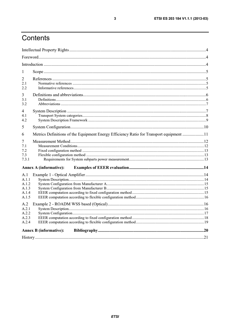
ETSI
3 Final draft ETSI ES 203 184 V1.1.1 (2012-12)
Contents
Intellectual Property Rights . 4
Foreword . 4
Introduction . 4
1 Scope . 5
2 References . 5
2.1 Normative references . 5
2.2 Informative references . 5
3 Definitions and abbreviations . 6
3.1 Definitions . 6
3.2 Abbreviations . 7
4 System Description . 7
4.1 Transport System categories. 8
4.2 System Description Framework . 9
5 System Configuration . 10
6 Metrics Definitions of the Equipment Energy Efficiency Ratio for Transport equipment . 11
7 Measurement Method . 12
7.1 Measurement Conditions . 12
7.2 Fixed configuration method . 13
7.3 Flexible configuration method . 13
7.3.1 Requirements for System subparts power measurement. 13
Annex A (informative): Examples of EEER evaluation . 14
A.1 Example 1 - Optical Amplifier . 14
A.1.1 System Description. 14
A.1.2 System Configuration from Manufacturer A . 15
A.1.3 System Configuration from Manufacturer B . 15
A.1.4 EEER computation according to fixed configuration method . 15
A.1.5 EEER computation according to flexible configuration method . 16
A.2 Example 2 - ROADM WSS based (Optical) . 16
A.2.1 System Description. 16
A.2.2 System Configuration . 17
A.2.3 EEER computation according to fixed configuration method . 18
A.2.4 EEER computation according to flexible configuration method . 19
Annex B (informative): Bibliography . 20
History . 21
ETSI
4 Final draft ETSI ES 203 184 V1.1.1 (2012-12)
Intellectual Property Rights
IPRs essential or potentially essential to the present document may have been declared to ETSI. The information
pertaining to these essential IPRs, if any, is publicly available for ETSI members and non-members, and can be found
in ETSI SR 000 314: "Intellectual Property Rights (IPRs); Essential, or potentially Essential, IPRs notified to ETSI in
respect of ETSI standards", which is available from the ETSI Secretariat. Latest updates are available on the ETSI Web
server (http://ipr.etsi.org).
Pursuant to the ETSI IPR Policy, no investigation, including IPR searches, has been carried out by ETSI. No guarantee
can be given as to the existence of other IPRs not referenced in ETSI SR 000 314 (or the updates on the ETSI Web
server) which are, or may be, or may become, essential to the present document.
Foreword
This final draft ETSI Standard (ES) has been produced by ETSI Technical Committee Environmental Engineering (EE),
and is now submitted for the ETSI standards Membership Approval Procedure.
Introduction
The present document defines the metric, methodology and the test conditions to evaluate the Equipment Energy
Efficiency Ratio (EEER) of Transport equipments. Energy efficiency is, in fact, becoming a relevant issue in
Telecommunication area, and increasing efficiency is a commitment in the Transport segment of the network too.
The present document adopts a "two steps" approach, with a system "description" (high level description of the
application, e.g. general characteristics like whole capacity, client and network interfaces with type and number, optical
features like gain, reach, noise figurer, etc.) and a system "configuration" (one of the possible
configuration/implementation of a given system description), as done in ATIS standard on Transport equipment
(see ATIS-0600015.02.2009 [2]).
The EEER is calculated with the same formula of the ATIS standard [2] but with the measurement conditions defined in
the present document. The EEER is evaluated according to the present document for a given fixed or flexible
configuration.
ETSI
5 Final draft ETSI ES 203 184 V1.1.1 (2012-12)
1 Scope
The present document defines the metric, methodology and the test conditions to evaluate the Equipment Energy
Efficiency Ratio (EEER) of Transport equipments. The Transport equipments covered will include all the transmission
equipment connected to the network by means of wired medium (i.e. copper or fiber), typically running at the network
OSI level 1. The present document also covers the equipment running at the network OSI level 2 (e.g. MPLS-TP) that
are not included in the ETSI standard on "Measurement Methods for Energy Efficiency of Router and Switch
Equipment" (the same approach is followed by ATIS standard on Transport equipment,
see ATIS-0600015.02.2009 [2]).
The present document is not applicable at node/network level but only at equipment level.
Examples of typical wired Transport equipments covered by the present document are switches or crosses connects
(SDH, OTN) and add/drop multiplexers (DWDM). The present document covers also simpler systems as
multiplexers/demultiplexers (DWDM), optical amplifiers, transponders.
Transport equipments that exploit radio or wireless interfaces (e.g. free space optics and point to point
wireless/microwave transport) are out of the scope of the present document. It is highlighted that ATIS standard for
transport equipment [2] includes wireless transport equipment.
2 References
References are either specific (identified by date of publication and/or edition number or version number) or
non-specific. For specific references, only the cited version applies. For non-specific references, the latest version of the
referenced document (including any amendments) applies.
Referenced documents which are not found to be publicly available in the expected location might be found at
http://docbox.etsi.org/Reference.
NOTE: While any hyperlinks included in this clause were valid at the time of publication, ETSI cannot guarantee
their long term validity.
2.1 Normative references
The following referenced documents are necessary for the application of the present document.
[1] ATIS-0600015.2009: "Energy Efficiency for Telecommunication Equipment: Methodology for
Measurement and Reporting - General Requirements", February, 2009.
[2] ATIS-0600015.02.2009: "Energy Efficiency for Telecommunication Equipment: Methodology for
Measurement and Reporting - Transport Requirements", February, 2009.
2.2 Informative references
The following referenced documents are not necessary for the application of the present document but they assist the
user with regard to a particular subject area.
[i.1] ETSI EN 300 132-2: "Environmental Engineering (EE); Power supply interface at the input to
telecommunications and datacom (ICT) equipment; Part 2: Operated by -48 V direct current (dc)".
ETSI
6 Final draft ETSI ES 203 184 V1.1.1 (2012-12)
3 Definitions and abbreviations
3.1 Definitions
For the purposes of the present document, the following terms and definitions apply:
Add Drop Multiplexer (ADM): network element that provides access to all, or some subset of the constituent signals
contained within an STM-N signal (in SDH) or in an OTU-k signal (in OTN) the ODUk and ODUflex can be accessed
in a similar way in the OTU. The constituent signals are added to (inserted), and/or dropped from (extracted) the
STM-N or OTU-k in OTN the OTU signal, as it passes through the ADM
card: part of an equipment implementing a given functionality (i.e. data interfaces, switching, control). Line cards with
data interfaces can have more ports
cross connect: apparatus enabling the termination of cable elements and their cross-connection, primarily by means of
patch cords or jumpers
Dense WDM (DWDM): WDM system characterised by an high density of optical signals on a given bandwidth
Digital Cross Connect (DXC): apparatus enabling the termination and the cross connection of signals (including
multiplexing and demultiplexing of signals according to a certain hierarchy) at electrical level
Forward Error Correction (FEC): technique which consists of transmitting the data in an encoded form such that the
redundancy added by the coding allows the decoding to detect and correct errors (e.g. in actual application the FEC is
used to extend the distance of transmission of optical signal)
hot-standby: state in which redundancy cards are not in use (stand-by), but are ready to work immediately when
needed
multi service protocol platform: transport equipment that is able to terminate and switch signals with more than one
protocol transport technology framing
Optical Add Drop Multiplexer (OADM): wavelength selective branching device (used in WDM transmission
systems) having a wavelength "drop" function in which one or more optical signals can be transferred from an input
port to either an output port or drop port(s) depending on the wavelength of the signal and also having a wavelength
"add" function in which optical signals presented to the add port(s) are also transferred to the output port (in OTN these
are the OCh signals)
optical amplifier: devices or subsystems in which optical signals can be amplified by means of the stimulated emission
taking place in a suitable active medium
Optical Cross Connect (OXC): apparatus enabling the termination and the cross connection of signal at optical level
(Optical) regenerator: transmitter-receiver combination device that performs the regeneration of an input optical
signal by means of conversion in the electrical domain and applying an FEC
(Optical) transponder: transmitter-receiver combination with or without pulse shaping and retiming that converts an
optical signal into another optical signal by a conversion into the electrical domain
passive (chromatic) dispersion compensator: passive component used to compensate the chromatic dispersion of an
optical path
port: part of a card in which a cable (typically a fiber) or a transceiver can be plugged to interconnect an equipment to
another compatible one
rack: free-standing or fixed structure for housing electrical and/or electronic and/or optical equipment, usually
organized in a number of slots
Reconfigurable OADM (ROADM): flexibly reconfigurable by means of control or management commands on the
node
slot: part of a rack for housing a card
switch: node that is capable of switching slots or packets/frames from one interface to another
ETSI
7 Final draft ETSI ES 203 184 V1.1.1 (2012-12)
transcesiver: combination of transmitter and receiver in a single package that is pluggable on a port of a line card with
compatible characteristics (in terms of rate and framing, for instance 40 GbEthernet)
transport equipment: transport equipment enables information transfer capabilities between originating and
terminating access service facilities
Wavelength Division Multiplexing (WDM): bidirectional multiplexing using different optical wavelength for up and
downstream signals
3.2 Abbreviations
For the purposes of the present document, the following abbreviations apply:
AC Alternating Current
CBR Constant Bit Rate signal
CWDM Coarse Wavelength Division Multiplexing
DWDM Dense Wavelength Division Multiplexing
DXC Digital Cross-Connect
EE Energy Efficiency
EEER Equipment Energy Efficiency Ratio
FEC Forward Error Correction
GMPLS Generalized Multi-Protocol Label Switching
IMIX Internet MIX
MPLS Multi Protocol Label Switching
MPLS-TP MPLS- Transport Profile
MSTP Multi Service Transport Platform
NTU Network Termination Unit
OA Optical Amplifier
OCh Optical Channel
ODU Optical Data Unit
OLA Optical Line Amplifier
OMS Optical Multiplex Section
OSI Open Systems Interconnection
OTN Optical Transport Network
OTS Optical Transmission Section
OTU Optica Transport Unit
OXC Optical Cross Connect
PT Packet Transport
ROADM Reconfigurable Optical Add/Drop Multiplexer
SDH Synchronous Digital Hierarchy
SFP Small Form-factor Pluggable
SNC Sub-Network Connection
STM Synchronous Transport Module
TEER Telecommunications Energy Efficiency Ratio
VBR Variable Bit Rate
WADM Wavelength Add/Drop Multiplexer
WDM Wavelength Division Multiplexing
WSON Wavelength Switched Optical Networks
WSS Wavelength Selective Switch
WXC Wavelength Cross-Connect
XFP 10 Gigabit Small Form Factor Pluggable Module
4 System Description
This clause contains the rules to describe a Transport system.
The System Description provides a specification in terms of qualitative (i.e. which type of equipment) and quantitative
(i.e. how many ports of a certain rate) features, without any details about practical/physical implementation (e.g. in
terms of cards arranged on a rack) and number of racks part of a single node.
ETSI
8 Final draft ETSI ES 203 184 V1.1.1 (2012-12)
It is suggested that the system description will be "implementation independent" and it shall be provided following the
framework reported in clause 4.2.
The present document covers the following non exhaustive list of Transport equipment types:
• Optical Amplifier, WDM Power Equalizer;
• WDM mux/demux (terminal for DWDM, CWDM);
• OADM, ROADM, OXC;
• SONET/SDH ADM, DXC;
• OTN ADM, DXC;
• Packet Transport switch (MPLS-TP);
• Multi Service Transport Platform (many combinations, i.e. SDH and Ethernet, OTN and Ethernet, OTN and
MPLS-TP, etc.);
• OTN-WDM platform (integrated DXC and ROADM node).
And other Transport equipments as defined in the scope of the present document.
4.1 Transport System categories
The following three Transport system categories are defined in order to properly provide the System Description.
Category A: terminal and signal conditioning equipment
This category, as regards signal handling by the system, is characterized by two sides: side a and side b (sometimes with
the meaning of Input and Output) as depicted in figure 1. The signals may be uni- or bi- directionally handled on each
of the two sides of the equipment.
The following equipments are examples of the category A:
• line OA;
• power equalizer;
• WDM terminal (mux/demux).
InIn / / ssididee a a
OutOut / s / siiddee b b
OuOut/t/ssiidde be b
In/sIn/siidde ae a
AA
AA
InIn / / side bside b
Out /Out / side side aa
Figure 1: Schematic representation for Category A Transport equipment:
unidirectional (on the left) or bidirectional (on the rigth)
Category B: switch and ADM without tributary add/drop ports
This category is characterized by switching or add/drop multiplexing functionalities and all the ports are used for
network interconnection (none of the ports is used for tributary add/drop function). Equipment belonging to this
category plays the role of pure transit equipment in a network.
ETSI
9 Final draft ETSI ES 203 184 V1.1.1 (2012-12)
The following equipment are examples of the category B:
• SDH switch or ADM;
• OTN switch or ADM;
• WDM ROADM;
• PT switch.
Figure 2 give a schematic representation of category B.
BB
Figure 2: Schematic representation for Category B Transport equipment
Category C: switch and ADM with tributary add/drop ports
This category is characterized by switching or add/drop multiplexing functionalities and the ports are used both for
network interconnection and for tributary add/drop function. Equipment belonging to this category plays the role of
node in a network where part of the switched traffic is terminated towards network clients.
A list of examples of equipment for category C is the same as the one provided for category B, but in case of category C
the equipment includes also tributary ports as depicted in figure 3.
TTribributarutary pory portsts
CC
Figure 3: Schematic representation for Category C Transport equipment
4.2 System Description Framework
Each system shall be described according to the following framework:
a) System Category in accordance with the definitions of clause 4.1.
b) Type of equipment (i.e. for cat
...
ETSI Standard
Environmental Engineering (EE);
Measurement Methods for Power Consumption in Transport
Telecommunication Networks Equipment
2 ETSI ES 203 184 V1.1.1 (2013-03)
Reference
DES/EE-00023
Keywords
energy efficiency, power, transport
ETSI
650 Route des Lucioles
F-06921 Sophia Antipolis Cedex - FRANCE
Tel.: +33 4 92 94 42 00 Fax: +33 4 93 65 47 16
Siret N° 348 623 562 00017 - NAF 742 C
Association à but non lucratif enregistrée à la
Sous-Préfecture de Grasse (06) N° 7803/88
Important notice
Individual copies of the present document can be downloaded from:
http://www.etsi.org
The present document may be made available in more than one electronic version or in print. In any case of existing or
perceived difference in contents between such versions, the reference version is the Portable Document Format (PDF).
In case of dispute, the reference shall be the printing on ETSI printers of the PDF version kept on a specific network drive
within ETSI Secretariat.
Users of the present document should be aware that the document may be subject to revision or change of status.
Information on the current status of this and other ETSI documents is available at
http://portal.etsi.org/tb/status/status.asp
If you find errors in the present document, please send your comment to one of the following services:
http://portal.etsi.org/chaircor/ETSI_support.asp
Copyright Notification
No part may be reproduced except as authorized by written permission.
The copyright and the foregoing restriction extend to reproduction in all media.
© European Telecommunications Standards Institute 2013.
All rights reserved.
TM TM TM
DECT , PLUGTESTS , UMTS and the ETSI logo are Trade Marks of ETSI registered for the benefit of its Members.
TM
3GPP and LTE™ are Trade Marks of ETSI registered for the benefit of its Members and
of the 3GPP Organizational Partners.
GSM® and the GSM logo are Trade Marks registered and owned by the GSM Association.
ETSI
3 ETSI ES 203 184 V1.1.1 (2013-03)
Contents
Intellectual Property Rights . 4
Foreword . 4
Introduction . 4
1 Scope . 5
2 References . 5
2.1 Normative references . 5
2.2 Informative references . 5
3 Definitions and abbreviations . 6
3.1 Definitions . 6
3.2 Abbreviations . 7
4 System Description . 7
4.1 Transport System categories. 8
4.2 System Description Framework . 9
5 System Configuration . 10
6 Metrics Definitions of the Equipment Energy Efficiency Ratio for Transport equipment . 11
7 Measurement Method . 12
7.1 Measurement Conditions . 12
7.2 Fixed configuration method . 13
7.3 Flexible configuration method . 13
7.3.1 Requirements for System subparts power measurement. 13
Annex A (informative): Examples of EEER evaluation . 14
A.1 Example 1 - Optical Amplifier . 14
A.1.1 System Description. 14
A.1.2 System Configuration from Manufacturer A . 15
A.1.3 System Configuration from Manufacturer B . 15
A.1.4 EEER computation according to fixed configuration method . 15
A.1.5 EEER computation according to flexible configuration method . 16
A.2 Example 2 - ROADM WSS based (Optical) . 16
A.2.1 System Description. 16
A.2.2 System Configuration . 17
A.2.3 EEER computation according to fixed configuration method . 18
A.2.4 EEER computation according to flexible configuration method . 19
Annex B (informative): Bibliography . 20
History . 21
ETSI
4 ETSI ES 203 184 V1.1.1 (2013-03)
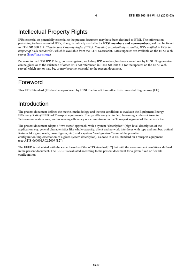
Intellectual Property Rights
IPRs essential or potentially essential to the present document may have been declared to ETSI. The information
pertaining to these essential IPRs, if any, is publicly available for ETSI members and non-members, and can be found
in ETSI SR 000 314: "Intellectual Property Rights (IPRs); Essential, or potentially Essential, IPRs notified to ETSI in
respect of ETSI standards", which is available from the ETSI Secretariat. Latest updates are available on the ETSI Web
server (http://ipr.etsi.org).
Pursuant to the ETSI IPR Policy, no investigation, including IPR searches, has been carried out by ETSI. No guarantee
can be given as to the existence of other IPRs not referenced in ETSI SR 000 314 (or the updates on the ETSI Web
server) which are, or may be, or may become, essential to the present document.
Foreword
This ETSI Standard (ES) has been produced by ETSI Technical Committee Environmental Engineering (EE).
Introduction
The present document defines the metric, methodology and the test conditions to evaluate the Equipment Energy
Efficiency Ratio (EEER) of Transport equipments. Energy efficiency is, in fact, becoming a relevant issue in
Telecommunication area, and increasing efficiency is a commitment in the Transport segment of the network too.
The present document adopts a "two steps" approach, with a system "description" (high level description of the
application, e.g. general characteristics like whole capacity, client and network interfaces with type and number, optical
features like gain, reach, noise figurer, etc.) and a system "configuration" (one of the possible
configuration/implementation of a given system description), as done in ATIS standard on Transport equipment
(see ATIS-0600015.02.2009 [i.2]).
The EEER is calculated with the same formula of the ATIS standard [i.2] but with the measurement conditions defined
in the present document. The EEER is evaluated according to the present document for a given fixed or flexible
configuration.
ETSI
5 ETSI ES 203 184 V1.1.1 (2013-03)
1 Scope
The present document defines the metric, methodology and the test conditions to evaluate the Equipment Energy
Efficiency Ratio (EEER) of Transport equipments. The Transport equipments covered will include all the transmission
equipment connected to the network by means of wired medium (i.e. copper or fiber), typically running at the network
OSI level 1. The present document also covers the equipment running at the network OSI level 2 (e.g. MPLS-TP) that
are not included in the ETSI standard on "Measurement Methods for Energy Efficiency of Router and Switch
Equipment" (the same approach is followed by ATIS standard on Transport equipment,
see ATIS-0600015.02.2009 [i.2]).
The present document is not applicable at node/network level but only at equipment level.
Examples of typical wired Transport equipments covered by the present document are switches or crosses connects
(SDH, OTN) and add/drop multiplexers (DWDM). The present document covers also simpler systems as
multiplexers/demultiplexers (DWDM), optical amplifiers, transponders.
Transport equipments that exploit radio or wireless interfaces (e.g. free space optics and point to point
wireless/microwave transport) are out of the scope of the present document. It is highlighted that ATIS standard for
transport equipment [i.2] includes wireless transport equipment.
2 References
References are either specific (identified by date of publication and/or edition number or version number) or
non-specific. For specific references, only the cited version applies. For non-specific references, the latest version of the
referenced document (including any amendments) applies.
Referenced documents which are not found to be publicly available in the expected location might be found at
http://docbox.etsi.org/Reference.
NOTE: While any hyperlinks included in this clause were valid at the time of publication, ETSI cannot guarantee
their long term validity.
2.1 Normative references
The following referenced documents are necessary for the application of the present document.
[1] ATIS-0600015.2009: "Energy Efficiency for Telecommunication Equipment: Methodology for
Measurement and Reporting - General Requirements", February, 2009.
2.2 Informative references
The following referenced documents are not necessary for the application of the present document but they assist the
user with regard to a particular subject area.
[i.1] ETSI EN 300 132-2: "Environmental Engineering (EE); Power supply interface at the input to
telecommunications and datacom (ICT) equipment; Part 2: Operated by -48 V direct current (dc)".
[i.2] ATIS-0600015.02.2009: "Energy Efficiency for Telecommunication Equipment: Methodology for
Measurement and Reporting - Transport Requirements", February, 2009.
ETSI
6 ETSI ES 203 184 V1.1.1 (2013-03)
3 Definitions and abbreviations
3.1 Definitions
For the purposes of the present document, the following terms and definitions apply:
Add Drop Multiplexer (ADM): network element that provides access to all, or some subset of the constituent signals
contained within an STM-N signal (in SDH) or in an OTU-k signal (in OTN) the ODUk and ODUflex can be accessed
in a similar way in the OTU. The constituent signals are added to (inserted), and/or dropped from (extracted) the
STM-N or OTU-k in OTN the OTU signal, as it passes through the ADM
card: part of an equipment implementing a given functionality (i.e. data interfaces, switching, control). Line cards with
data interfaces can have more ports
cross connect: apparatus enabling the termination of cable elements and their cross-connection, primarily by means of
patch cords or jumpers
Dense WDM (DWDM): WDM system characterised by an high density of optical signals on a given bandwidth
Digital Cross Connect (DXC): apparatus enabling the termination and the cross connection of signals (including
multiplexing and demultiplexing of signals according to a certain hierarchy) at electrical level
Forward Error Correction (FEC): technique which consists of transmitting the data in an encoded form such that the
redundancy added by the coding allows the decoding to detect and correct errors (e.g. in actual application the FEC is
used to extend the distance of transmission of optical signal)
hot-standby: state in which redundancy cards are not in use (stand-by), but are ready to work immediately when
needed
multi service protocol platform: transport equipment that is able to terminate and switch signals with more than one
protocol transport technology framing
Optical Add Drop Multiplexer (OADM): wavelength selective branching device (used in WDM transmission
systems) having a wavelength "drop" function in which one or more optical signals can be transferred from an input
port to either an output port or drop port(s) depending on the wavelength of the signal and also having a wavelength
"add" function in which optical signals presented to the add port(s) are also transferred to the output port (in OTN these
are the OCh signals)
optical amplifier: devices or subsystems in which optical signals can be amplified by means of the stimulated emission
taking place in a suitable active medium
Optical Cross Connect (OXC): apparatus enabling the termination and the cross connection of signal at optical level
(Optical) regenerator: transmitter-receiver combination device that performs the regeneration of an input optical
signal by means of conversion in the electrical domain and applying an FEC
(Optical) transponder: transmitter-receiver combination with or without pulse shaping and retiming that converts an
optical signal into another optical signal by a conversion into the electrical domain
passive (chromatic) dispersion compensator: passive component used to compensate the chromatic dispersion of an
optical path
port: part of a card in which a cable (typically a fiber) or a transceiver can be plugged to interconnect an equipment to
another compatible one
rack: free-standing or fixed structure for housing electrical and/or electronic and/or optical equipment, usually
organized in a number of slots
Reconfigurable OADM (ROADM): flexibly reconfigurable by means of control or management commands on the
node
slot: part of a rack for housing a card
switch: node that is capable of switching slots or packets/frames from one interface to another
ETSI
7 ETSI ES 203 184 V1.1.1 (2013-03)
transcesiver: combination of transmitter and receiver in a single package that is pluggable on a port of a line card with
compatible characteristics (in terms of rate and framing, for instance 40 GbEthernet)
transport equipment: transport equipment enables information transfer capabilities between originating and
terminating access service facilities
Wavelength Division Multiplexing (WDM): bidirectional multiplexing using different optical wavelength for up and
downstream signals
3.2 Abbreviations
For the purposes of the present document, the following abbreviations apply:
AC Alternating Current
ATIS Alliance for Telecommunications Industry Solutions
CBR Constant Bit Rate signal
CWDM Coarse Wavelength Division Multiplexing
DWDM Dense Wavelength Division Multiplexing
DXC Digital Cross-Connect
EE Energy Efficiency
EEER Equipment Energy Efficiency Ratio
FEC Forward Error Correction
GMPLS Generalized Multi-Protocol Label Switching
IMIX Internet MIX
MPLS Multi Protocol Label Switching
MPLS-TP MPLS- Transport Profile
OA Optical Amplifier
OCh Optical Channel
ODU Optical Data Unit
OLA Optical Line Amplifier
OSI Open Systems Interconnection
OTN Optical Transport Network
OTS Optical Transmission Section
OTU Optica Transport Unit
OXC Optical Cross Connect
PT Packet Transport
ROADM Reconfigurable Optical Add/Drop Multiplexer
SDH Synchronous Digital Hierarchy
SFP Small Form-factor Pluggable
STM Synchronous Transport Module
TEER Telecommunications Energy Efficiency Ratio
VBR Variable Bit Rate
WDM Wavelength Division Multiplexing
WSON Wavelength Switched Optical Networks
WSS Wavelength Selective Switch
WXC Wavelength Cross-Connect
XFP 10 Gigabit Small Form Factor Pluggable Module
4 System Description
This clause contains the rules to describe a Transport system.
The System Description provides a specification in terms of qualitative (i.e. which type of equipment) and quantitative
(i.e. how many ports of a certain rate) features, without any details about practical/physical implementation (e.g. in
terms of cards arranged on a rack) and number of racks part of a single node.
It is suggested that the system description will be "implementation independent" and it shall be provided following the
framework reported in clause 4.2.
ETSI
8 ETSI ES 203 184 V1.1.1 (2013-03)
The present document covers the following non exhaustive list of Transport equipment types:
• Optical Amplifier, WDM Power Equalizer;
• WDM mux/demux (terminal for DWDM, CWDM);
• OADM, ROADM, OXC;
• SONET/SDH ADM, DXC;
• OTN ADM, DXC;
• Packet Transport switch (MPLS-TP);
• Multi Service Transport Platform (many combinations, i.e. SDH and Ethernet, OTN and Ethernet, OTN and
MPLS-TP, etc.);
• OTN-WDM platform (integrated DXC and ROADM node).
And other Transport equipments as defined in the scope of the present document.
4.1 Transport System categories
The following three Transport system categories are defined in order to properly provide the System Description.
Category A: terminal and signal conditioning equipment
This category, as regards signal handling by the system, is characterized by two sides: side a and side b (sometimes with
the meaning of Input and Output) as depicted in figure 1. The signals may be uni- or bi- directionally handled on each
of the two sides of the equipment.
The following equipments are examples of the category A:
• line OA;
• power equalizer;
• WDM terminal (mux/demux).
InIn / / ssididee a a
OutOut / s / siiddee b b
OuOut/t/ssiidde be b
In/sIn/siidde ae a
AA
AA
InIn / / side bside b
Out /Out / side side aa
Figure 1: Schematic representation for Category A Transport equipment:
unidirectional (on the left) or bidirectional (on the rigth)
Category B: switch and ADM without tributary add/drop ports
This category is characterized by switching or add/drop multiplexing functionalities and all the ports are used for
network interconnection (none of the ports is used for tributary add/drop function). Equipment belonging to this
category plays the role of pure transit equipment in a network.
ETSI
9 ETSI ES 203 184 V1.1.1 (2013-03)
The following equipment are examples of the category B:
• SDH switch or ADM;
• OTN switch or ADM;
• WDM ROADM;
• PT switch.
Figure 2 give a schematic representation of category B.
BB
Figure 2: Schematic representation for Category B Transport equipment
Category C: switch and ADM with tributary add/drop ports
This category is characterized by switching or add/drop multiplexing functionalities and the ports are used both for
network interconnection and for tributary add/drop function. Equipment belonging to this category plays the role of
node in a network where part of the switched traffic is terminated towards network clients.
A list of examples of equipment for category C is the same as the one provided for category B, but in case of category C
the equipment includes also tributary ports as depicted in figure 3.
TTribributarutary pory portsts
CC
Figure 3: Schematic representation for Category C Transport equipment
4.2 System Description Framework
Each system shall be described according to the following framework:
a) System Category in accordance with the definitions of clause 4.1.
b) Type of equipment (i.e. for category A: OA, WDM terminal; for category B: switch, Add/Drop without
tributary ports; for categor
...