


ISO/FDIS 20816-3
(Main)Mechanical vibration — Measurement and evaluation of machine vibration — Part 3: Industrial machines with operating speeds between 120 r/min and 30 000 r/min
General Information
- Abstract
This document specifies the general requirements for evaluating the vibration of various coupled industrial machine types with a power above 15 kW and operating speeds between 120 r/min and 30 000 r/min when measurements are made in-situ. Guidelines for applying evaluation criteria are provided for measurements taken on non-rotating and rotating parts under normal operating conditions. The guidelines are presented in terms of both steady running vibration values and in terms of changes to vibration magnitude, which can occur in these steady values. The numerical values presented are intended to serve as guidelines based on worldwide machine experience, but shall be applied with due regard to specific machine features which can cause these values to be inappropriate. In general, the condition of a machine is assessed by consideration of both the shaft vibration and the associated structural vibration, as well as specific frequency components, which do not always relate to the broadband severity values presented. The machine types covered by this document include: a) steam turbines and generators with outputs less than or equal to 40 MW (see Note 1 and Note 2); b) steam turbines and generators with outputs greater than 40 MW which normally operate at speeds other than 1 500 r/min, 1 800 r/min, 3 000 r/min or 3 600 r/min (although generators seldom fall into this category) (see Note 1); c) rotary compressors; d) industrial gas turbines with outputs less than or equal to 3 MW (see Note 2); e) turbofans; f) electric motors of any type, if the coupling is flexible. When a motor is rigidly coupled to a machine type covered by any other part of ISO20816, the motor may be assessed either against that other part or against ISO 20816-3; g) rolls and mills; h) conveyors; i) variable speed couplings; and j) blowers or fans (see Note 3). NOTE 1 Land based steam turbines, gas turbines and generators of greater than 40 MW capacity, which run at 1 500 r/min, 1 800 r/min, 3 000 r/min or 3 600 r/min are covered by the requirements of ISO 20816-2. Generators in hydro-electric plants are covered by ISO 20816-5. NOTE 2 Gas turbines of power greater than 3 MW are covered by ISO 20816-4. NOTE 3 The vibration criteria presented in this document are generally only applicable to fans with power ratings greater than 300 kW or fans which are not flexibly supported. As and when circumstances permit, recommendations for other types of fans, including those of lightweight sheet-metal construction, will be prepared. Until these recommendations are available, classifications can be agreed between the manufacturer and the customer; using results of previous operational experience (see also ISO 14694). Machinery including a geared stage can fall under the scope of this document. For performing acceptance tests of gearboxes please refer to ISO 20816-9. The following types of industrial machine are not covered by this document: k) land-based gas turbines, steam turbines and generators with power outputs greater than 40 MW and speeds of 1 500 r/min, 1 800 r/min, 3 000 r/min or 3 600 r/min (see ISO20816‑2); l) gas turbine sets with power outputs greater than 3 MW (see ISO20816‑4); m) machine sets in hydraulic power generating and pumping plants (see ISO20816‑5); n) reciprocating machines and machines solidly coupled to reciprocating machines (see ISO10816‑6); o) rotordynamic pumps and any integrated or solidly coupled electric motors where the impeller is mounted directly on the motor shaft or is rigidly attached to it (see ISO10816‑7); p) reciprocating compressor systems (see ISO 20816-8); q) rotary positive displacement compressors (e. g. screw compressors); r) submerged motor-pumps; and s) wind turbines (see ISO10816‑21). The requirements of this document apply to in-situ broad-band vibration measurements taken on the shafts, bearings, bearing pedestals, or housings of machines under steady-state operating conditions within their nominal
- Status
- Not Published
- Technical Committee
- ISO/TC 108/SC 2 - Measurement and evaluation of mechanical vibration and shock as applied to machines, vehicles and structures
- Drafting Committee
- ISO/TC 108/SC 2/WG 1 - Rotordynamics and vibration of machines
- Current Stage
- 5020 - FDIS ballot initiated: 2 months. Proof sent to secretariat
- Start Date
- 11-Aug-2026
- Completion Date
- 11-Aug-2026
Buy Documents

ISO/FDIS 20816-3 - Mechanical vibration — Measurement and evaluation of machine vibration — Part 3: Industrial machines with operating speeds between 120 r/min and 30 000 r/min

REDLINE ISO/FDIS 20816-3 - Mechanical vibration — Measurement and evaluation of machine vibration — Part 3: Industrial machines with operating speeds between 120 r/min and 30 000 r/min
Overview
ISO/FDIS 20816-3:2026 focuses on the measurement and evaluation of mechanical vibration in industrial machines with operating speeds between 120 r/min and 30,000 r/min. This international standard, developed by the International Organization for Standardization (ISO), establishes general requirements and provides guidelines for assessing in-situ vibration in various coupled industrial machine types with power above 15 kW. Evaluation criteria within this standard help ensure reliable machine performance, safety, and maintenance planning by addressing vibration on both rotating and non-rotating parts in actual operating environments.
Key Topics
Applicable Machine Types:
- Steam turbines and generators (≤ 40 MW and those > 40 MW at non-standard speeds)
- Rotary compressors, industrial gas turbines (≤ 3 MW), turbofans
- Electric motors (flexibly coupled)
- Rolls and mills, conveyors, blowers or fans (above 300 kW or not flexibly supported)
- Machines including gear units (see also ISO 20816-9)
Vibration Measurement Procedures:
- Requirements for measurement positions, sensor orientation, and mounting
- Considerations for measuring on shafts, bearings, pedestals, and housings
- Use of both continuous and non-continuous (periodic) monitoring systems
Evaluation and Classification:
- Guidelines for assessment based on vibration magnitude (steady-state) and changes over time
- Classification of machines by power and shaft height into three groups for tailored criteria
- Use of evaluation zones (A-D) to indicate vibration severity and recommend actions
Operational Monitoring:
- Consideration of normal operating conditions for accurate assessment
- Differentiation between vibration originating from the machine versus external sources
Applications
ISO/FDIS 20816-3 is essential for professionals in industries such as power generation, manufacturing, and heavy machinery maintenance. Practical applications include:
Machine Condition Monitoring:
Enables ongoing assessment of shaft, bearing, and housing vibrations to maintain operational reliability and avoid unplanned downtime.Acceptance Testing:
Provides standardized vibration assessment during machine commissioning and after major servicing to ensure compliance with contractual and safety requirements.Preventive Maintenance:
Facilitates the early detection of abnormal vibration trends, supporting data-driven maintenance scheduling and minimization of costly breakdowns.Quality Assurance:
Assists manufacturers and end-users in establishing and adhering to internationally recognized vibration limits for industrial machines.Risk Management:
Guides the establishment of alarm and trip values for safe machine operation, helping prevent damage and reduce operational risk.
Related Standards
ISO/FDIS 20816-3 is part of the broader ISO 20816 and ISO 10816 series for vibration measurement and evaluation. Related standards include:
- ISO 20816-1: Mechanical vibration - General guidelines for measurement and evaluation
- ISO 20816-2: Vibration evaluation for land-based steam and gas turbines (> 40 MW at standard speeds)
- ISO 20816-4: Vibration in gas turbine sets (> 3 MW)
- ISO 20816-5: Hydraulic power generating and pumping plant machinery
- ISO 20816-9: Acceptance tests for gearboxes
- ISO 14694: Vibration criteria for fans
- ISO 2954: Requirements for instruments used in vibration severity measurements
- ISO 10817-1: Rotating shaft vibration measuring systems
Conclusion
By following the guidelines established in ISO/FDIS 20816-3, organizations can implement standardized vibration measurement and evaluation practices across a wide range of industrial machines. This supports improved machinery reliability, safety, maintenance efficiency, and quality assurance, aligning operations with global best practices in mechanical vibration management.
Relations
- Effective Date
- 29-Jun-2024
Buy Documents
ISO/FDIS 20816-3 - Mechanical vibration — Measurement and evaluation of machine vibration — Part 3: Industrial machines with operating speeds between 120 r/min and 30 000 r/min
REDLINE ISO/FDIS 20816-3 - Mechanical vibration — Measurement and evaluation of machine vibration — Part 3: Industrial machines with operating speeds between 120 r/min and 30 000 r/min
Get Certified
Connect with accredited certification bodies for this standard

BSMI (Bureau of Standards, Metrology and Inspection)
Taiwan's standards and inspection authority.
Sponsored listings
Frequently Asked Questions
ISO/FDIS 20816-3 is a draft published by the International Organization for Standardization (ISO). Its full title is "Mechanical vibration — Measurement and evaluation of machine vibration — Part 3: Industrial machines with operating speeds between 120 r/min and 30 000 r/min". This standard covers: This document specifies the general requirements for evaluating the vibration of various coupled industrial machine types with a power above 15 kW and operating speeds between 120 r/min and 30 000 r/min when measurements are made in-situ. Guidelines for applying evaluation criteria are provided for measurements taken on non-rotating and rotating parts under normal operating conditions. The guidelines are presented in terms of both steady running vibration values and in terms of changes to vibration magnitude, which can occur in these steady values. The numerical values presented are intended to serve as guidelines based on worldwide machine experience, but shall be applied with due regard to specific machine features which can cause these values to be inappropriate. In general, the condition of a machine is assessed by consideration of both the shaft vibration and the associated structural vibration, as well as specific frequency components, which do not always relate to the broadband severity values presented. The machine types covered by this document include: a) steam turbines and generators with outputs less than or equal to 40 MW (see Note 1 and Note 2); b) steam turbines and generators with outputs greater than 40 MW which normally operate at speeds other than 1 500 r/min, 1 800 r/min, 3 000 r/min or 3 600 r/min (although generators seldom fall into this category) (see Note 1); c) rotary compressors; d) industrial gas turbines with outputs less than or equal to 3 MW (see Note 2); e) turbofans; f) electric motors of any type, if the coupling is flexible. When a motor is rigidly coupled to a machine type covered by any other part of ISO20816, the motor may be assessed either against that other part or against ISO 20816-3; g) rolls and mills; h) conveyors; i) variable speed couplings; and j) blowers or fans (see Note 3). NOTE 1 Land based steam turbines, gas turbines and generators of greater than 40 MW capacity, which run at 1 500 r/min, 1 800 r/min, 3 000 r/min or 3 600 r/min are covered by the requirements of ISO 20816-2. Generators in hydro-electric plants are covered by ISO 20816-5. NOTE 2 Gas turbines of power greater than 3 MW are covered by ISO 20816-4. NOTE 3 The vibration criteria presented in this document are generally only applicable to fans with power ratings greater than 300 kW or fans which are not flexibly supported. As and when circumstances permit, recommendations for other types of fans, including those of lightweight sheet-metal construction, will be prepared. Until these recommendations are available, classifications can be agreed between the manufacturer and the customer; using results of previous operational experience (see also ISO 14694). Machinery including a geared stage can fall under the scope of this document. For performing acceptance tests of gearboxes please refer to ISO 20816-9. The following types of industrial machine are not covered by this document: k) land-based gas turbines, steam turbines and generators with power outputs greater than 40 MW and speeds of 1 500 r/min, 1 800 r/min, 3 000 r/min or 3 600 r/min (see ISO20816‑2); l) gas turbine sets with power outputs greater than 3 MW (see ISO20816‑4); m) machine sets in hydraulic power generating and pumping plants (see ISO20816‑5); n) reciprocating machines and machines solidly coupled to reciprocating machines (see ISO10816‑6); o) rotordynamic pumps and any integrated or solidly coupled electric motors where the impeller is mounted directly on the motor shaft or is rigidly attached to it (see ISO10816‑7); p) reciprocating compressor systems (see ISO 20816-8); q) rotary positive displacement compressors (e. g. screw compressors); r) submerged motor-pumps; and s) wind turbines (see ISO10816‑21). The requirements of this document apply to in-situ broad-band vibration measurements taken on the shafts, bearings, bearing pedestals, or housings of machines under steady-state operating conditions within their nominal
This document specifies the general requirements for evaluating the vibration of various coupled industrial machine types with a power above 15 kW and operating speeds between 120 r/min and 30 000 r/min when measurements are made in-situ. Guidelines for applying evaluation criteria are provided for measurements taken on non-rotating and rotating parts under normal operating conditions. The guidelines are presented in terms of both steady running vibration values and in terms of changes to vibration magnitude, which can occur in these steady values. The numerical values presented are intended to serve as guidelines based on worldwide machine experience, but shall be applied with due regard to specific machine features which can cause these values to be inappropriate. In general, the condition of a machine is assessed by consideration of both the shaft vibration and the associated structural vibration, as well as specific frequency components, which do not always relate to the broadband severity values presented. The machine types covered by this document include: a) steam turbines and generators with outputs less than or equal to 40 MW (see Note 1 and Note 2); b) steam turbines and generators with outputs greater than 40 MW which normally operate at speeds other than 1 500 r/min, 1 800 r/min, 3 000 r/min or 3 600 r/min (although generators seldom fall into this category) (see Note 1); c) rotary compressors; d) industrial gas turbines with outputs less than or equal to 3 MW (see Note 2); e) turbofans; f) electric motors of any type, if the coupling is flexible. When a motor is rigidly coupled to a machine type covered by any other part of ISO20816, the motor may be assessed either against that other part or against ISO 20816-3; g) rolls and mills; h) conveyors; i) variable speed couplings; and j) blowers or fans (see Note 3). NOTE 1 Land based steam turbines, gas turbines and generators of greater than 40 MW capacity, which run at 1 500 r/min, 1 800 r/min, 3 000 r/min or 3 600 r/min are covered by the requirements of ISO 20816-2. Generators in hydro-electric plants are covered by ISO 20816-5. NOTE 2 Gas turbines of power greater than 3 MW are covered by ISO 20816-4. NOTE 3 The vibration criteria presented in this document are generally only applicable to fans with power ratings greater than 300 kW or fans which are not flexibly supported. As and when circumstances permit, recommendations for other types of fans, including those of lightweight sheet-metal construction, will be prepared. Until these recommendations are available, classifications can be agreed between the manufacturer and the customer; using results of previous operational experience (see also ISO 14694). Machinery including a geared stage can fall under the scope of this document. For performing acceptance tests of gearboxes please refer to ISO 20816-9. The following types of industrial machine are not covered by this document: k) land-based gas turbines, steam turbines and generators with power outputs greater than 40 MW and speeds of 1 500 r/min, 1 800 r/min, 3 000 r/min or 3 600 r/min (see ISO20816‑2); l) gas turbine sets with power outputs greater than 3 MW (see ISO20816‑4); m) machine sets in hydraulic power generating and pumping plants (see ISO20816‑5); n) reciprocating machines and machines solidly coupled to reciprocating machines (see ISO10816‑6); o) rotordynamic pumps and any integrated or solidly coupled electric motors where the impeller is mounted directly on the motor shaft or is rigidly attached to it (see ISO10816‑7); p) reciprocating compressor systems (see ISO 20816-8); q) rotary positive displacement compressors (e. g. screw compressors); r) submerged motor-pumps; and s) wind turbines (see ISO10816‑21). The requirements of this document apply to in-situ broad-band vibration measurements taken on the shafts, bearings, bearing pedestals, or housings of machines under steady-state operating conditions within their nominal
ISO/FDIS 20816-3 is classified under the following ICS (International Classification for Standards) categories: 17.160 - Vibrations, shock and vibration measurements. The ICS classification helps identify the subject area and facilitates finding related standards.
ISO/FDIS 20816-3 has the following relationships with other standards: It is inter standard links to ISO 20816-3:2022. Understanding these relationships helps ensure you are using the most current and applicable version of the standard.
ISO/FDIS 20816-3 is available in PDF format for immediate download after purchase. The document can be added to your cart and obtained through the secure checkout process. Digital delivery ensures instant access to the complete standard document.
Standards Content (Sample)
FINAL DRAFT
International
Standard
ISO/TC 108/SC 2
Mechanical vibration —
Secretariat: DIN
Measurement and evaluation of
Voting begins on:
machine vibration —
2026-08-11
Part 3:
Voting terminates on:
2026-10-06
Industrial machines with operating
speeds between 120 r/min and 30
000 r/min
Vibrations mécaniques — Mesurage et évaluation des vibrations
de machines —
Partie 3: Machines industrielles avec une vitesse de
fonctionnement comprise entre 120 r/min et 30 000 r/min
RECIPIENTS OF THIS DRAFT ARE INVITED TO SUBMIT,
WITH THEIR COMMENTS, NOTIFICATION OF ANY
RELEVANT PATENT RIGHTS OF WHICH THEY ARE AWARE
AND TO PROVIDE SUPPOR TING DOCUMENTATION.
IN ADDITION TO THEIR EVALUATION AS
BEING ACCEPTABLE FOR INDUSTRIAL, TECHNO-
LOGICAL, COMMERCIAL AND USER PURPOSES, DRAFT
INTERNATIONAL STANDARDS MAY ON OCCASION HAVE
TO BE CONSIDERED IN THE LIGHT OF THEIR POTENTIAL
TO BECOME STAN DARDS TO WHICH REFERENCE MAY BE
MADE IN NATIONAL REGULATIONS.
Reference number
FINAL DRAFT
International
Standard
ISO/TC 108/SC 2
Mechanical vibration —
Secretariat: DIN
Measurement and evaluation of
Voting begins on:
machine vibration —
Part 3:
Voting terminates on:
Industrial machines with operating
speeds between 120 r/min and 30
000 r/min
Vibrations mécaniques — Mesurage et évaluation des vibrations
de machines —
Partie 3: Machines industrielles avec une vitesse de
fonctionnement comprise entre 120 r/min et 30 000 r/min
RECIPIENTS OF THIS DRAFT ARE INVITED TO SUBMIT,
WITH THEIR COMMENTS, NOTIFICATION OF ANY
RELEVANT PATENT RIGHTS OF WHICH THEY ARE AWARE
AND TO PROVIDE SUPPOR TING DOCUMENTATION.
© ISO 2026
IN ADDITION TO THEIR EVALUATION AS
All rights reserved. Unless otherwise specified, or required in the context of its implementation, no part of this publication may
BEING ACCEPTABLE FOR INDUSTRIAL, TECHNO-
LOGICAL, COMMERCIAL AND USER PURPOSES, DRAFT
be reproduced or utilized otherwise in any form or by any means, electronic or mechanical, including photocopying, or posting on
INTERNATIONAL STANDARDS MAY ON OCCASION HAVE
the internet or an intranet, without prior written permission. Permission can be requested from either ISO at the address below
TO BE CONSIDERED IN THE LIGHT OF THEIR POTENTIAL
or ISO’s member body in the country of the requester.
TO BECOME STAN DARDS TO WHICH REFERENCE MAY BE
MADE IN NATIONAL REGULATIONS.
ISO copyright office
CP 401 • Ch. de Blandonnet 8
CH-1214 Vernier, Geneva
Phone: +41 22 749 01 11
Email: copyright@iso.org
Website: www.iso.org
Published in Switzerland Reference number
ii
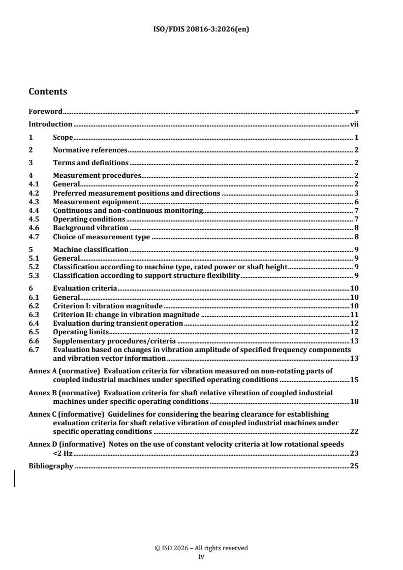
Contents Page
Foreword .iv
Introduction .v
1 Scope . 1
2 Normative references . 2
3 Terms and definitions . 2
4 Measurement procedures . 2
4.1 General .2
4.2 Preferred measurement positions and directions .2
4.3 Measurement equipment.6
4.4 Continuous and non-continuous monitoring .7
4.5 Operating conditions .7
4.6 Background vibration .8
4.7 Choice of measurement type .8
5 Machine classification . 9
5.1 General .9
5.2 Classification according to machine type, rated power or shaft height .9
5.3 Classification according to support structure flexibility .9
6 Evaluation criteria .10
6.1 General .10
6.2 Criterion I: vibration magnitude .10
6.2.1 General .10
6.2.2 Evaluation zones .10
6.2.3 Acceptance criteria .11
6.2.4 Evaluation zone limits .11
6.3 Criterion II: change in vibration magnitude . .11
6.4 Evaluation during transient operation . 12
6.5 Operating limits . 12
6.5.1 General . 12
6.5.2 Setting ALARMs . 12
6.5.3 Setting TRIPs . 13
6.6 Supplementary procedures/criteria . 13
6.7 Evaluation based on changes in vibration amplitude of specified frequency components
and vibration vector information . 13
Annex A (normative) Evaluation criteria for vibration measured on non-rotating parts of
coupled industrial machines under specified operating conditions . 14
Annex B (normative) Evaluation criteria for shaft relative vibration of coupled industrial
machines under specific operating conditions . 17
Annex C (informative) Guidelines for considering the bearing clearance for establishing
evaluation criteria for shaft relative vibration of coupled industrial machines under
specific operating conditions .21
Annex D (informative) Notes on the use of constant velocity criteria at low rotational speeds
<2 Hz.22
Bibliography .24
iii
Foreword
ISO (the International Organization for Standardization) is a worldwide federation of national standards
bodies (ISO member bodies). The work of preparing International Standards is normally carried out through
ISO technical committees. Each member body interested in a subject for which a technical committee
has been established has the right to be represented on that committee. International organizations,
governmental and non-governmental, in liaison with ISO, also take part in the work. ISO collaborates closely
with the International Electrotechnical Commission (IEC) on all matters of electrotechnical standardization.
The procedures used to develop this document and those intended for its further maintenance are specified
in the ISO/IEC Directives, Part 1. In particular, the different approval criteria needed for the different types
of ISO documents should be noted. This document was drafted in accordance with the editorial rules of the
ISO/IEC Directives, Part 2 (see www.iso.org/directives).
Attention is drawn to the possibility that some of the elements of this document may be the subject of patent
rights. ISO shall not be held responsible for identifying any or all such patent rights. Details of any patent
rights identified during the development of the document will be in the Introduction and/or on the ISO list of
patent declarations received (see www.iso.org/patents).
Any trade name used in this document is information given for the convenience of users and does not
constitute an endorsement.
For an explanation of the voluntary nature of standards, the meaning of ISO specific terms and expressions
related to conformity assessment, as well as information about ISO's adherence to the World Trade
Organization (WTO) principles in the Technical Barriers to Trade (TBT), see www.iso.org/iso/foreword.html.
This document was prepared by Technical Committee ISO/TC 108, Mechanical vibration, shock and condition
monitoring, Subcommittee SC 2, Measurement and evaluation of mechanical vibration and shock as applied to
machines, vehicles and structures.
This second edition of ISO 20816-3 cancels and replaces the first edition (ISO 20816-3:2022), which has
been technically revised.
The main changes are as follows:
— title was adjusted to align with expanded scope;
— wording in the Scope was expanded to include machines of Group 3 with a rated power ≤15 kW;
— wording was aligned with ISO 20816-1;
— Figure 4 and Figure 5 were updated;
— wording in 5.2 was adjusted to include machines of Group 3;
— recommendations for TRIP limits were removed in 6.5.3;
— vibration severity zones for machines of Group 3 were added in Table A.3;
— overview of vibration severity zones was added in Table A.4;
— text below Figure B.1 was transformed into Note 1 and Note 2 of the figure;
— Bibliography was updated;
— the entire document was editorially revised.
A list of all parts in the ISO 20816 series and ISO 10816 series can be found on the ISO website.
Any feedback or questions on this document should be directed to the user’s national standards body. A
complete listing of these bodies can be found at www.iso.org/members.html.
iv
Introduction
This document provides specific guidance for assessing
a) vibration severity measured near bearings, on bearing pedestals or housings of industrial machines
when measurements are made in-situ, and
b) the radial shaft vibration severity on coupled industrial machines.
Evaluation criteria, based on previous experience, are given for use as guidelines for assessing the vibratory
conditions of such industrial machines. However, note that these criteria do not form the only basis for
evaluating vibration severity.
v
FINAL DRAFT International Standard ISO/FDIS 20816-3:2026(en)
Mechanical vibration — Measurement and evaluation of
machine vibration —
Part 3:
Industrial machines with operating speeds between 120 r/
min and 30 000 r/min
1 Scope
This document specifies the general requirements for evaluating the vibration of various coupled industrial
machine types with operating speeds between 120 r/min and 30 000 r/min when measurements are made
in-situ. This document gives guidelines for applying evaluation criteria for measurements taken on non-
rotating and rotating parts under normal operating conditions. The guidelines are presented in terms of
both steady running vibration values and in terms of changes to vibration values which can occur in these
steady values.
This document is applicable to these machine types:
a) steam turbines and generators with outputs ≤40 MW;
b) steam turbines and generators with output power >40 MW and operating speeds other than 1 500 r/
min, 1 800 r/min, 3 000 r/min or 3 600 r/min (although generators seldom fall into this category);
c) rotary compressors;
d) industrial gas turbines with output power ≤3 MW;
e) turbofans;
f) electric motors of any type, if the coupling is flexible, when a motor is rigidly coupled to a machine type
covered by any other part of ISO 20816 series;
g) rolls and mills;
h) conveyors;
j) blowers or fans with a rated power greater than 300 kW or which are not flexibly supported, see also
ISO 14694.
This document is applicable to machines including a gear unit. ISO 20816-9 contains information for special
acceptance tests related to gear units.
This document is applicable to in-situ broad-band vibration measurements taken on the shafts, bearings,
bearing pedestals or housings of machines close to bearings under steady-state operating conditions within
their operating speed range. The requirements relate to both acceptance tests and operational monitoring.
The evaluation criteria can be applied to both continuous and non-continuous monitoring.
This document is applicable to machines which have gears or rolling bearings but does not address the
diagnostic evaluation of the condition of those gears or bearings.
This document is applicable only for the vibration produced by the machine set itself and not for vibration
that is transmitted to the machine set from external sources.
2 Normative references
The following documents are referred to in the text in such a way that some or all of their content constitutes
requirements of this document. For dated references, only the edition cited applies. For undated references,
the latest edition of the referenced document (including any amendments) applies.
ISO 2041, Mechanical vibration, shock and condition monitoring — Vocabulary
ISO 2954, Mechanical vibration of rotating and reciprocating machinery — Requirements for instruments for
measuring vibration severity
ISO 10817-1, Rotating shaft vibration measuring systems — Part 1: Relative and absolute sensing of radial
vibration
ISO 20816-1, Mechanical vibration — Measurement and evaluation of machine vibration — Part 1: General
guidelines
3 Terms and definitions
For the purposes of this document, the terms and definitions given in ISO 2041 and ISO 20816-1 apply.
ISO and IEC maintain terminology databases for use in standardization at the following addresses:
— ISO Online browsing platform: available at https:// www .iso .org/ obp
— IEC Electropedia: available at https:// www .electropedia .org/
4 Measurement procedures
4.1 General
The measurement procedures that shall be followed and the instrumentation which shall be used are
specified in ISO 20816-1 subject to the requirements given in this clause.
The measuring system shall not be influenced by environmental factors such as
a) temperature variations,
b) magnetic fields, including magnetisation of the shaft,
c) sound fields,
d) power source variations,
e) sensor cable length (some designs of shaft vibration probe require matched cable lengths),
f) sensor cable faults, and
g) sensor orientation,
h) Data collection by collector (e.g. offline and intermittent using handheld analyser/meter). Coiled cable/
other cables movement.
Particular attention shall be paid to ensure that the sensors are correctly mounted and that such mountings
can influence the measurements taken.
4.2 Preferred measurement positions and directions
It is common practice to measure vibration on non-rotating parts, or rotating parts (shaft relative
vibration), or both. Unless stated otherwise, this document refers to shaft relative vibration when referring
to vibration displacement measurements taken on rotating parts. See 4.3 and ISO 10817-1 for further details
of instrumentation for radial vibration measurement on rotating parts.
Measurements taken on non-rotating parts shall be taken on the bearing housing or other structural parts
which significantly respond to the dynamic forces transmitted from the rotating elements at the bearing
locations and represent the overall vibration of the machine. In some machines it is not possible to access
the bearing housings directly. In such cases the measurements shall reasonably represent the vibration of
the bearing housing and do not include any local resonances, amplification or damping. Thin or otherwise
flexible surfaces (e.g. fan covers or cowlings) shall be avoided. It can be necessary to confirm the repeatability
of the vibration values and the validity of the measurements taken at the measurement positions (e.g. by
taking measurements at several positions and comparing the results).
The chosen positions and directions of the vibration measurements shall provide adequate sensitivity to
the machine dynamic forces. Typically, this requires two orthogonal radial measurement positions on each
bearing cap, housing or pedestal so that an orbit can be visualised. The sensors may be placed at any angular
position on them. Vertical and transverse directions are preferred for horizontally mounted machines.
For vertical or inclined machines, the position that gives the maximum vibration reading shall be one of
those used. In some cases, it is also recommended to measure in the axial direction (see 6.2.1). The specific
measurement positions and directions used shall be recorded along with the measurement results.
A single radial vibration sensor may be used on a bearing cap or pedestal in place of the more typical pair of
orthogonal vibration transducers if that is known to provide adequate information on the magnitude of the
machine vibration. Caution shall be exercised when evaluating vibration from a single vibration sensor in
a measurement plane, to ensure that it provides a reasonable approximation of the maximum value in that
plane.
For accuracy in diagnosis, it is suggested to collect data from three directions at each data collection location
(bearing housing).
For figures showing preferred measurement positions for both shaft vibration and housing vibration see
ISO 20816-1, which are reproduced in Figure 1 to Figure 6 for convenience.
Figure 1 — Preferred measurement positions and directions for pedestal bearings
Figure 2 — Preferred measurement positions and directions for bearing housings
Figure 3 — Preferred measurement positions and directions for machines
Figure 4 — Preferred measurement positions and directions for vertical machine sets
Key
1 signal conditioning units
2 non-contacting displacement probe
3 shaft
4 bearing housings
5 bearings
a
To signal processing.
Figure 5 — Preferred measurement positions for measurements on rotating shafts
Key
1 signal conditioning units
2 shaft
3 non-contacting displacement probe
a
To signal processing.
Figure 6 — Mounting of non-contacting probes for the measurement of shaft relative vibration
4.3 Measurement equipment
For monitoring purposes, the measurement equipment used shall be capable of measuring broad-band root-
mean-square (r.m.s.) vibration with a flat response over a frequency range of at least 10 Hz to 1 000 Hz. For
machines with operating speeds ≤600 r/min, the lower limit of the flat response frequency range shall not
be greater than 2 Hz.
For measurements taken on rotating parts, the methods using non-contacting vibration sensors are most
commonly used and are preferred. The equipment used shall be capable of measuring overall vibration up
to at least a frequency equivalent to 3,5 times the maximum operating speed. The measurement equipment
used shall meet the requirements of ISO 10817-1.
For measurements taken on non-rotating parts, the measurement equipment used shall meet the
requirements of ISO 2954. Depending on the evaluation criteria, this requires measurements of displacement
or velocity or a combination of them (see ISO 20816-1). Where accelerometers are mounted on stationary
parts of the machine (as is common practice), their output shall be integrated to provide a velocity signal.
Double integration of acceleration to provide a displacement signal may be used, but caution shall be
exercised when doing that due to the possibility of introducing high noise levels. High pass filtering and/or
alternative digital computation of the displacement value can provide more accurate values.
For diagnostic purposes, the linear frequency range of the system shall generally cover frequencies from
0,2 times the lowest rotational speed to 2,5 times the highest excitation frequency of interest (generally not
exceeding 10 kHz). For further information see ISO 13373-1, ISO 13373-2 and ISO 13373-3.
4.4 Continuous and non-continuous monitoring
It is common practice on large or critical machines to have instrumentation installed for continuous on-line
monitoring of vibration values at key measurement positions for both condition monitoring and protection
purposes. In some cases, such instrumentation provides an input to the control system.
For many machines, continuous monitoring of the vibration parameters is not carried out. Changes in the
machine’s condition (e.g. unbalance, bearing performance, structural looseness and alignment) can be
detected with sufficient reliability by taking periodic measurements. The guideline vibration values can
be applied to periodic measurements provided that the measurement position, frequency response and
mounting is in accordance with the requirements of this document.
Instruments for measuring the vibration of rotating parts are usually permanently installed, but in some
cases their output may only be measured periodically.
Vibration measurements can be taken on non-rotating parts by temporarily attached vibration sensors.
However, inaccessible machines may have permanently installed vibration sensors wired back or wireless
linked to an accessible location or have a non-continuous logging system installed.
4.5 Operating conditions
Vibration measurements shall be made when the rotor and bearings have reached their steady-state
operating temperatures and with the machine running under specified conditions (e.g. running at rated
speed, voltage, flow, pressure and load).
For machines with varying operating speeds or loads, vibration measurements shall be made under all
conditions at which the machine is expected to operate for prolonged periods. The maximum measured
magnitude under these conditions shall be considered representative of vibration severity.
It is not always possible to wait for the desired operating conditions before taking a vibration measurement.
In such cases the influence of operating conditions shall be considered when assessing vibration severity.
Operating conditions, which can affect vibration, include
a) machine load,
b) process temperature,
c) valve positions,
d) flows,
e) ambient temperature,
f) fluid levels, and
g) filter differential pressure.
When operating conditions vary from measurement to measurement, those with the most significant
influence on the machine shall be recorded. For best repeatability, newly acquired measurements shall be
judged against those taken previously under similar conditions.
4.6 Background vibration
If the measured vibration magnitude is greater than the acceptance criteria and excessive background
vibration is suspected, measurements shall be made with the machine shut down to determine the extent
of any external influence. Corrective action can be necessary to reduce the effect of background vibration, if
the measured vibration magnitude with the machine stationary exceeds the smaller of
a) 25 % of the magnitude measured when the machine is running, or
b) 25 % of the Zone B/C boundary (see 6.2.2) appropriate to the machine type.
4.7 Choice of measurement type
In this document, guidelines are provided for measurement on both rotating and non-rotating parts. The
choice of which measurement type to use depends upon the characteristics of the machine and the faults
which need to be detected.
The advantages or disadvantages of vibration measurements on rotating or non-rotating parts shall be
considered based upon:
a) Rated speed of the machine and highest frequency of interest:
Measurements taken on non-rotating parts are more sensitive to higher frequencies than measurements
taken on rotating parts.
b) Bearing type:
Rolling bearings have very small clearances and transmit shaft vibration effectively into their housings.
Therefore, measurements taken on non-rotating parts are usually sufficient to enable effective vibration
monitoring and machine assessment. Journal bearings provide high damping and larger clearances, so
shaft vibration is often a useful additional parameter to measure.
c) Machine type:
For protection purposes machines with internal clearances comparable to the vibration magnitude
can require the measurement of shaft relative vibration (see Annex C). Monitoring of components that
generate multiples of rotor speed, e.g. vanes, gear teeth (including gear pumps) and blades rotor bars,
benefit from the higher frequency range available with measurements taken on non-rotating parts.
d) Ratio of shaft mass to pedestal mass:
Light shafts in heavy pedestals transmit little vibration into the bearing housing, so shaft relative
vibration measurements provide a better indication of machine behaviour.
e) Shaft flexibility:
Shaft relative vibration measurements provide a more sensitive indication of vibration severity in
machines with flexible shafts.
f) Support structure flexibility:
Flexible support structures lead to a higher vibration response of non-rotating parts.
g) Experience:
Where a large body of experience exists relating to one particular measurement type, it is useful to
continue to use it in similar situations.
For more detailed information on the choice of the appropriate measurement method, see ISO 13373-1.
Considerations relating to ease of access, longevity of sensors and cost of installation are also relevant to the
final decision taken (see ISO 17359).
5 Machine classification
5.1 General
In this document, the vibration severity is classified according to these parameters:
a) machine type;
b) rated power or shaft height;
c) support structure flexibility.
5.2 Classification according to machine type, rated power or shaft height
Significant differences in design and support structures require a separation into three different machine
groups with regard to either their rated power or shaft height, H.
NOTE The shaft height, H, of a machine is defined as the distance, measured on the machine ready for delivery,
between the centreline of the shaft and its base plane.
Machines of Group 1, Group 2 and Group 3 can have horizontal, vertical or inclined shafts and can be mounted
on rigid or flexible support structures.
Group 1: Large machines with rated power >300 kW; electrical machines with a shaft height H ≥ 315 mm.
Group 2: Medium-sized machines with a rated power 15 kW < P ≤ 300 kW; electrical machines with a shaft
height 160 mm ≤ H < 315 mm.
Group 3: Small-sized machines with a rated power ≤15 kW; electrical machines with a shaft height
56 mm ≤ H < 160 mm.
5.3 Classification according to support structure flexibility
Two classes are used to describe the support structure flexibility in specific directions:
a) rigid;
b) flexible.
These support structure conditions are determined by the relationship between the machine and foundation
flexibilities. If the lowest natural frequency of the system exceeds the excitation frequency by >25 % then
the machine may be considered rigid.
The excitation frequency is usually related to rotational speed, but significant other excitations (e.g. vane
passing or gear mesh) can be important. Machines on anti-vibration mounts shall be classified as flexible.
EXAMPLE Electric motors, mainly with low rated speeds, usually have rigid support structures. Turbo-generators
or compressors, with rated powers >10 MW and vertical machine sets usually have flexible support stuctures.
It is possible for machines to be rigid in one direction and flexible in another (e.g. pedestal bearings tend to
vibrate much more in the transverse direction than in the vertical direction).
If the class of the machine support structure cannot be readily determined from drawings and calculation,
it can be determined by testing.
6 Evaluation criteria
6.1 General
ISO 20816-1 provides a general description of the two evaluation criteria used to assess vibration severity
on various machine types. The first considers the magnitude of the observed broad-band vibration and the
second considers changes (both increases and decreases) in the magnitude of the observed broad-band
vibration.
6.2 Criterion I: vibration magnitude
6.2.1 General
For measurements taken on rotating parts, the vibration severity is the higher magnitude of the broad-band
peak-to-peak displacement measured in the two orthogonal measurement directions.
For measurements taken on non-rotating parts, the vibration severity is the highest r.m.s. magnitude of the
broad-band velocity measured at or near a bearing.
Criterion I is concerned with defining limits for vibration magnitude consistent with acceptable dynamic
loads on the bearings and acceptable vibration transmission into the environment through the support
structure and foundation. The maximum vibration magnitude observed at each bearing or pedestal is
assessed against the evaluation zones for the support class. The evaluation zones have been established from
experience with the same machine type and, if due regard is paid to them, acceptable machine operation
can be expected. If only one measuring direction is used, ensure that it provides adequate information (for
further information see ISO 20816-1).
The evaluation zone boundary values are presented for the specified steady-state operating conditions at
the rated speed and load ranges. They apply for normal slow changes in load but do not apply when different
conditions exist or during transient changes (e.g. during start-up and shut down and when passing through
resonance ranges). See 6.4 for further guidance.
It is not common practice to measure axial vibration on radial load-carrying bearings during continuous
operational monitoring. Such measurements are primarily used during periodic vibration surveys or for
diagnostic purposes. Certain faults are more easily detected in the axial direction. Specific axial vibration
criteria only apply in the case of thrust bearings where axial vibration correlates with axial pulsations,
misalignment and coupling unbalance, which can cause damage to the axial load-carrying surfaces.
The evaluation zone boundary values shown in Table A.1, Table A.2 and Table A.3 apply to radial vibration on
all bearings and to axial vibration on thrust bearings.
6.2.2 Evaluation zones
6.2.2.1 General
Evaluation zones are specified to enable a qualitative assessment of the vibration of a given machine under
steady-state conditions at rated speed and to provide guidelines on possible actions.
Zone A: The vibration of newly commissioned machines normally falls within this zone.
NOTE The effort to achieve vibration within Zone A can be disproportionate and unnecessary.
Zone B: Machines with vibration within this zone are normally considered acceptable for unrestricted long-
term operation.
Zone C: Machines with vibration within this zone are normally considered unsatisfactory for long-term
continuous operation. Generally, the machine may be operated for a limited period in this condition until a
suitable opportunity arises for remedial action.
Zone D: Vibration values within this zone are normally considered to be of sufficient severity to cause
damage to the machine.
6.2.2.2 Evaluation zone boundaries
Zone boundary values are not intended to serve as acceptance criteria (see also 6.2.3) In certain cases,
there can be specific features associated with a particular machine, which justify the use of different
zone boundaries values (higher or lower). In such cases, it is usually necessary to explain the reasons for
the different zone boundaries and, in particular, to confirm that the machine will not be endangered by
operating it with higher vibration magnitudes.
6.2.3 Acceptance criteria
Acceptance criteria shall always be subject to agreement between the machine manufacturer and customer,
and prior negotiation is encouraged. The evaluation zones provide a basis for defining acceptance criteria
for operation under specific conditions, but the numerical values assigned to the zone boundaries are not
themselves intended to serve as acceptance criteria.
Historically, for new machines, acceptance criteria have been specified in Zone A or Zone B, but normally do
not exceed 1,25 times the Zone A/B boundary. Different acceptance criteria can be agreed upon, based on
specific design characteristics and/or fleet experience with similar machines.
Contractual acceptance tests shall be carried out under clearly specified duration and operating parameters
(e.g. duty, rotating speed, flow, temperature and/or pressure). After major component replacement,
balancing, maintenance or service activities, acceptance criteria shall consider the scope of activity - and the
vibration behaviour of the machine prior to servicing.
6.2.4 Evaluation zone limits
The evaluation criteria for vibration severity, changes in vibration magnitude and operating limits are given
in Annex A for measurements on non-rotating parts and in Annex B for measurements taken on rotating
parts.
6.3 Criterion II: change in vibration magnitude
Criterion II provides an assessment of a change in vibration magnitude from a previously established
reference value. A significant change in broad-band vibration magnitude can occur, which requires some
action even though Zone C of Criterion I has not been reached. Such changes can be instantaneous or
progressive over time and can indicate incipient damage or some other irregularity. Criterion II is specifically
based on the change in broad-band vibration magnitude that occurs under steady-state operating conditions.
Steady-state operating conditions shall be interpreted to include small changes in the machine power or
operating conditions.
When Criterion II is applied, the vibration measurements being compared shall be taken at the same
measurement position and direction and under approximately the same machine operating conditions.
Obvious changes in the normal vibration magnitudes, regardless of their total amount, shall be investigated
so that a dangerous situation can be avoided. When an increase or decrease in vibration magnitude exceeds
25 % of the Zone B/C boundary, as specified in Annex A and Annex B, it shall be considered significant,
particularly if it is sudden. Diagnostic investigations shall then be initiated to ascertain the reason for the
change and to determine what further actions are appropriate.
The 25 % value is given as a guideline for a significant change in vibration magnitude, but other values can
be used based on experience with a specific machine. Where available the 25 % value can also be applied to
vibration vector information based on a specific frequency of interest. This approach can be a more sensitive
test for identifying changes in vibration magnitude (see ISO 20816-1:—, Annex D).
Where a machine shows variability in vibration behaviour, further statistical measures can be applied to the
results before Criterion II is applied so as to avoid excessive false positive results occurring.
6.4 Evaluation during transient operation
The evaluation criteria specified in Annex A and Annex B are intended for use under steady-state conditions.
In general, higher vibration magnitudes can occur during transient machine states. In particular, when a
machine with a flexible support structure runs up to the operating speed or coasts down from operating
speed, high vibration magnitudes can be measured as the rotor passes through its critical speed. In
addition, machines can experience transient higher vibration magnitudes due to alignment changes or shaft
distortions during initial warming through. The response of the machine to operating and external ambient
conditions shall be considered when evaluation vibration severity. Whilst the evaluation criteria given here
are not intended for machine supervision during such conditions, operation up to the Zone C/D boundary
can be considered acceptable for limited periods of transient operation. In the case of run-up, run-down or
overspeed, the appropriate values for acceptable vibration are shown in Table 1.
Table 1 — Guidelines for maximum vibration severity during run-up, run-down or overspeed
Operating speed range
Vibration measured on non-rotat- Vibration measured on rotating
ing parts parts
(in relation to rated speed)
(see Table A.1 to and Table A.3) (see Formula B.1 to Formula B.3)
%
<20 n/a (see Note) 1,5 × C/D zone boundary
20 to 90 1,0 × C/D zone boundary 1,5 × C/D zone boundary
>90 1,0 × C/D zone boundary 1,0 × C/D zone boundary
NOTE The ratio of vibration displacement to velocity is inversely proportional to frequency. Hence, for measurements made on
non-rotating parts, there are drawbacks in using a constant velocity criterion at operating speeds <20 % of rated speed.
6.5 Operating limits
6.5.1 General
For long-term operation, it is common practice to establish operating limits. These limits take the form of
ALARMs and TRIPs.
ALARM: To provide a warning that a specified value of vibration magnitude has been reached or a significant
change has occurred upon which remedial action can be necessary. In general, if an ALARM situation occurs,
operation can continue for a period whilst investigations are carried out to identify the reason for the change
in vibration and specify any remedial action.
TRIP: To specify the vibration magnitude beyond which further operation of the machine can cause damage.
If the TRIP value is exceeded, immediate action shall be taken to reduce the vibration or to shut down the
machine.
Different operating limits, reflecting differences in dynamic load and support stiffness, may be specified for
different measurement positions and directions.
6.5.2 Setting ALARMs
ALARMs can vary considerably, for different machines. The values chosen shall be set relative to a baseline
value determined from experience for the measurement position or direction for that particular machine.
It is recommended that the ALARM is set higher than the baseline value by an amount equal to 25 % of the
Zone B/C boundary. If the baseline value is low, the ALARM can be below the Zone B/C boundary.
Where there is no established baseline value (e.g. with a new machine) the initial ALARMs shall be based
either on experience with other similar machines or relative to agreed acceptance values. After a period, the
steady-state baseline value will be established, and the ALARMs s shall be adjusted accordingly.
It is recommended that the ALARM does not exceed 1,25 times the Zone B/C boundary.
If the steady-state baseline value changes (e.g. after a machine overhaul) the ALARMs shall be revised
accordingly. Different operating ALARMs can then exist for different bearings on the machine, reflecting
differences in dynamic load and bearing support structural stiffnesses.
6.5.3 Setting TRIPs
TRIPs relate to the mechanical integrity of the machine and are dependent on specific design features which
enable t
...
ISO /TC 108/SC 2
Secretariat: DIN
Date: 2026-06-01xx
Mechanical vibration — Measurement and evaluation of machine
vibration —
Part 3:
Industrial machines with operating speeds between 120 r/min
and 30 000 r/min
Vibrations mécaniques — Mesurage et évaluation des vibrations de machines — —
Partie 3: Machines industrielles avec une vitesse de fonctionnement comprise entre 120 r/min et 30 000
r/min
FDIS stage
All rights reserved. Unless otherwise specified, or required in the context of its implementation, no part of this
publication may be reproduced or utilized otherwise in any form or by any means, electronic or mechanical, including
photocopying, or posting on the internet or an intranet, without prior written permission. Permission can be requested
from either ISO at the address below or ISO’s member body in the country of the requester.
ISO copyright office
CP 401 • Ch. de Blandonnet 8
CH-1214 Vernier, Geneva
Phone: + 41 22 749 01 11
EmailE-mail: copyright@iso.org
Website: www.iso.org
Published in Switzerland
ii
iii
Contents
Foreword . v
Introduction . vii
1 Scope . 1
2 Normative references . 2
3 Terms and definitions . 2
4 Measurement procedures . 2
4.1 General . 2
4.2 Preferred measurement positions and directions . 3
4.3 Measurement equipment . 6
4.4 Continuous and non-continuous monitoring . 7
4.5 Operating conditions . 7
4.6 Background vibration . 8
4.7 Choice of measurement type . 8
5 Machine classification . 9
5.1 General . 9
5.2 Classification according to machine type, rated power or shaft height . 9
5.3 Classification according to support structure flexibility . 9
6 Evaluation criteria . 10
6.1 General . 10
6.2 Criterion I: vibration magnitude . 10
6.3 Criterion II: change in vibration magnitude . 11
6.4 Evaluation during transient operation . 12
6.5 Operating limits . 12
6.6 Supplementary procedures/criteria . 13
6.7 Evaluation based on changes in vibration amplitude of specified frequency components
and vibration vector information . 13
Annex A (normative) Evaluation criteria for vibration measured on non-rotating parts of
coupled industrial machines under specified operating conditions . 15
Annex B (normative) Evaluation criteria for shaft relative vibration of coupled industrial
machines under specific operating conditions . 18
Annex C (informative) Guidelines for considering the bearing clearance for establishing
evaluation criteria for shaft relative vibration of coupled industrial machines under
specific operating conditions . 22
Annex D (informative) Notes on the use of constant velocity criteria at low rotational speeds
<2 Hz . 23
Bibliography . 25
iv
Foreword
ISO (the International Organization for Standardization) is a worldwide federation of national standards
bodies (ISO member bodies). The work of preparing International Standards is normally carried out through
ISO technical committees. Each member body interested in a subject for which a technical committee has
been established has the right to be represented on that committee. International organizations,
governmental and non-governmental, in liaison with ISO, also take part in the work. ISO collaborates closely
with the International Electrotechnical Commission (IEC) on all matters of electrotechnical standardization.
The procedures used to develop this document and those intended for its further maintenance are specified
in the ISO/IEC Directives, Part 1. In particular, the different approval criteria needed for the different types
of ISO documents should be noted. This document was drafted in accordance with the editorial rules of the
ISO/IEC Directives, Part 2 (see www.iso.org/directives).
Attention is drawn to the possibility that some of the elements of this document may be the subject of patent
rights. ISO shall not be held responsible for identifying any or all such patent rights. Details of any patent
rights identified during the development of the document will be in the Introduction and/or on the ISO list of
patent declarations received (see www.iso.org/patents).
Any trade name used in this document is information given for the convenience of users and does not
constitute an endorsement.
For an explanation of the voluntary nature of standards, the meaning of ISO specific terms and expressions
related to conformity assessment, as well as information about ISO's adherence to the World Trade
Organization (WTO) principles in the Technical Barriers to Trade (TBT), see
www.iso.org/iso/foreword.html.
This document was prepared by Technical Committee ISO/TC 108, Mechanical vibration, shock and condition
monitoring, Subcommittee SC 2, Measurement and evaluation of mechanical vibration and shock as applied to
machines, vehicles and structures.
This second edition of ISO 20816-3 cancels and replaces the first edition (ISO 20816-3:2022), which has
been technically revised.
The main changes are as follows:
— — title was adjusted to align with expanded scope;
— — wording in the Scope was expanded to include machines of Group 3 with a rated
power ≤ 15 kW;
— — wording was aligned with ISO 20816-1;
— Figure 4— Figure 4 and Figure 5Figure 5 were updated;
— — wording in 5.25.2 was adjusted to include machines of Group 3;
— — recommendations for TRIP limits were removed in 6.5.36.5.3;;
— — vibration severity zones for machines of Group 3 were added in Table A.3Table A.3;;
— — overview of vibration severity zones was added in Table A.4Table A.4;;
— — text below Figure B.1Figure B.1 was transformed into Note 1 and Note 2 of the figure;
v
— — Bibliography was updated;
— — the entire document was editorially revised.
A list of all parts in the ISO 20816 series and ISO 10816 series can be found on the ISO website.
Any feedback or questions on this document should be directed to the user’s national standards body. A
complete listing of these bodies can be found at www.iso.org/members.html.
vi
Introduction
This document provides specific guidance for assessing
a) a) vibration severity measured near bearings, on bearing pedestals or housings of industrial
machines when measurements are made in-situ, and
b) b) the radial shaft vibration severity on coupled industrial machines.
Evaluation criteria, based on previous experience, are given for use as guidelines for assessing the vibratory
conditions of such industrial machines. However, note that these criteria do not form the only basis for
evaluating vibration severity.
vii
Mechanical vibration — Measurement and evaluation of machine
vibration —
Part 3:
Industrial machines with operating speeds between 120 r/min and
30 000 r/min
1 Scope
This document specifies the general requirements for evaluating the vibration of various coupled industrial
machine types with operating speeds between 120 r/min and 30 000 r/min when measurements are made
in-situ. This document gives guidelines for applying evaluation criteria for measurements taken on non-
rotating and rotating parts under normal operating conditions. The guidelines are presented in terms of
both steady running vibration values and in terms of changes to vibration values which can occur in these
steady values.
This document is applicable to these machine types:
a) a) steam turbines and generators with outputs ≤ 40 MW;
b) b) steam turbines and generators with output power > 40 MW and operating speeds other than
1 500 r/min, 1 800 r/min, 3 000 r/min or 3 600 r/min (although generators seldom fall into this
category);
c) c) rotary compressors;
d) d) industrial gas turbines with output power ≤ 3 MW;
e) e) turbofans;
f) f) electric motors of any type, if the coupling is flexible, when a motor is rigidly coupled to a
machine type covered by any other part of ISO 20816 series, also that other part;
g) g) rolls and mills;
h) h) conveyors;
i) j) blowers or fans with a rated power greater than 300 kW or which are not flexibly supported,
see also ISO 14694.
This document is applicable to machines including a gear unit. ISO 20816-9 contains information for special
acceptance tests related to gear units.
This document is applicable to in-situ broad-band vibration measurements taken on the shafts, bearings,
bearing pedestals or housings of machines close to bearings under steady-state operating conditions within
their operating speed range. The requirements relate to both acceptance tests and operational monitoring.
The evaluation criteria can be applied to both continuous and non-continuous monitoring.
This document is applicable to machines which have gears or rolling bearings but does not address the
diagnostic evaluation of the condition of those gears or bearings.
This document is applicable only for the vibration produced by the machine set itself and not for vibration
that is transmitted to the machine set from external sources.
2 Normative references
The following documents are referred to in the text in such a way that some or all of their content constitutes
requirements of this document. For dated references, only the edition cited applies. For undated references,
the latest edition of the referenced document (including any amendments) applies.
ISO 2041, Mechanical vibration, shock and condition monitoring — Vocabulary
ISO 2954, Mechanical vibration of rotating and reciprocating machinery — Requirements for instruments for
measuring vibration severity
ISO 10817--1, Rotating shaft vibration measuring systems — Part 1: Relative and absolute sensing of radial
vibration
ISO 20816--1, Mechanical vibration — Measurement and evaluation of machine vibration — Part 1: General
guidelines
3 Terms and definitions
For the purposes of this document, the terms and definitions given in ISO 2041 and ISO 20816-1 apply.
ISO and IEC maintain terminology databases for use in standardization at the following addresses:
— — ISO Online browsing platform: available at https://www.iso.org/obp
— — IEC Electropedia: available at https://www.electropedia.org/
4 Measurement procedures
4.1 General
The measurement procedures that shall be followed and the instrumentation which shall be used are
specified in ISO 20816--1 subject to the requirements given in this clause.
The Measuringmeasuring system shall not be influenced by environmental factors such as
a) a) temperature variations,
b) b) magnetic fields, including magnetisation of the shaft,
c) c) sound fields,
d) d) power source variations,
e) e) sensor cable length (some designs of shaft vibration probe require matched cable lengths),
f) f) sensor cable faults, and
g) g) sensor orientation,
h) h) Data collection by collector (e.g. offline, and intermittent using handheld analyser/ meter).
Coiled cable / /other cables movement.
Particular attention shall be paid to ensure that the sensors are correctly mounted and that such mountings
can influence the measurements taken.
4.2 Preferred measurement positions and directions
It is common practice to measure vibration on non-rotating parts, or rotating parts (shaft relative vibration),
or both. Unless stated otherwise, this document refers to shaft relative vibration when referring to vibration
displacement measurements taken on rotating parts. See 4.34.3 and ISO 10817-1 for further details of
instrumentation for radial vibration measurement on rotating parts.
Measurements taken on non-rotating parts shall be taken on the bearing housing or other structural parts
which significantly respond to the dynamic forces transmitted from the rotating elements at the bearing
locations and represent the overall vibration of the machine. In some machines it is not possible to access
the bearing housings directly. In such cases the measurements shall reasonably represent the vibration of
the bearing housing and do not include any local resonances, amplification or damping. Thin or otherwise
flexible surfaces (e.g. fan covers or cowlings) shall be avoided. It can be necessary to confirm the
repeatability of the vibration values and the validity of the measurements taken at the measurement
positions (e.g. by taking measurements at several positions and comparing the results).
The chosen positions and directions of the vibration measurements shall provide adequate sensitivity to the
machine dynamic forces. Typically, this requires two orthogonal radial measurement positions on each
bearing cap, housing or pedestal so that an orbit can be visualised. The sensors may be placed at any angular
position on them. Vertical and transverse directions are preferred for horizontally mounted machines. For
vertical or inclined machines, the position that gives the maximum vibration reading shall be one of those
used. In some cases, it is also recommended to measure in the axial direction (see 6.2.16.2.1).). The specific
measurement positions and directions used shall be recorded along with the measurement results.
A single radial vibration sensor may be used on a bearing cap or pedestal in place of the more typical pair of
orthogonal vibration transducers if that is known to provide adequate information on the magnitude of the
machine vibration. Caution shall be exercised when evaluating vibration from a single vibration sensor in a
measurement plane, to ensure that it provides a reasonable approximation of the maximum value in that
plane.
For accuracy in diagnosis, it is suggested to collect data from three directions at each data collection location
(bearing housing).
For figures showing preferred measurement positions for both shaft vibration and housing vibration see
ISO 20816--1, which are reproduced in Figure 1Figure 1 to Figure 6Figure 6 for convenience.
20816-3_ed2fig1.EPS
Figure 1 — Preferred measurement positions and directions for pedestal bearings
20816-3_ed2fig2.EPS
Figure 2 — Preferred measurement positions and directions for bearing housings
20816-3_ed2fig3.EPS
Figure 3 — Preferred measurement positions and directions for machines
20816-3_ed2fig4.EPS
Figure 4 — Preferred measurement positions and directions for vertical machine sets
20816-3_ed2fig5.EPS
Key
1 signal conditioning units
2 non-contacting displacement probe
3 shaft
4 bearing housings
5 bearings
a
To signal processing.
Figure 5 — Preferred measurement positions for measurements on rotating shafts
20816-3_ed2fig6.EPS
Key
1 signal conditioning units
2 shaft
3 non-contacting displacement probe
a
To signal processing.
Figure 6 — Mounting of non-contacting probes for the measurement of shaft relative vibration
4.3 Measurement equipment
For monitoring purposes, the measurement equipment used shall be capable of measuring broad-band root-
mean-square (r.m.s.) vibration with a flat response over a frequency range of at least 10 Hz to 1 000 Hz. For
machines with operating speeds ≤ 600 r/min, the lower limit of the flat response frequency range shall not
be greater than 2 Hz.
For measurements taken on rotating parts, the methods using non-contacting vibration sensors are most
commonly used and are preferred. The equipment used shall be capable of measuring overall vibration up to
at least a frequency equivalent to 3,5 times the maximum operating speed. The measurement equipment
used shall meet the requirements of ISO 10817-1.
For measurements taken on non-rotating parts, the measurement equipment used shall meet the
requirements of ISO 2954. Depending on the evaluation criteria, this requires measurements of
displacement or velocity or a combination of them (see ISO 20816--1). Where accelerometers are mounted
on stationary parts of the machine (as is common practice), their output shall be integrated to provide a
velocity signal. Double integration of acceleration to provide a displacement signal may be used, but caution
shall be exercised when doing that due to the possibility of introducing high noise levels. High pass filtering
and/or alternative digital computation of the displacement value can provide more accurate values.
For diagnostic purposes, the linear frequency range of the system shall generally cover frequencies from
0,2 times the lowest rotational speed to 2,5 times the highest excitation frequency of interest (generally not
exceeding 10 kHz). For further information see ISO 13373--1, ISO 13373--2 and ISO 13373--3.
4.4 Continuous and non-continuous monitoring
It is common practice on large or critical machines to have instrumentation installed for continuous on-line
monitoring of vibration values at key measurement positions for both condition monitoring and protection
purposes. In some cases, such instrumentation provides an input to the control system.
For many machines, continuous monitoring of the vibration parameters is not carried out. Changes in the
machine’s condition (e.g. unbalance, bearing performance, structural looseness and alignment) can be
detected with sufficient reliability by taking periodic measurements. The guideline vibration values can be
applied to periodic measurements provided that the measurement position, frequency response and
mounting is in accordance with the requirements of this document.
Instruments for measuring the vibration of rotating parts are usually permanently installed, but in some
cases their output may only be measured periodically.
Vibration measurements can be taken on non-rotating parts by temporarily attached vibration sensors.
However, inaccessible machines may have permanently installed vibration sensors wired back or wireless
linked to an accessible location or have a non-continuous logging system installed.
4.5 Operating conditions
Vibration measurements shall be made when the rotor and bearings have reached their steady-state
operating temperatures and with the machine running under specified conditions (e.g. running at rated
speed, voltage, flow, pressure and load).
For machines with varying operating speeds or loads, vibration measurements shall be made under all
conditions at which the machine is expected to operate for prolonged periods. The maximum measured
magnitude under these conditions shall be considered representative of vibration severity.
It is not always possible to wait for the desired operating conditions before taking a vibration measurement.
In such cases the influence of operating conditions shall be considered when assessing vibration severity.
Operating conditions, which can affect vibration, include:
a) a) machine load;,
b) b) process temperature;,
c) c) valve positions;,
d) d) flows;,
e) e) ambient temperature;,
f) f) fluid levels;, and
g) g) filter differential pressure.
When operating conditions vary from measurement to measurement, those with the most significant
influence on the machine shall be recorded. For best repeatability, newly acquired measurements shall be
judged against those taken previously under similar conditions.
4.6 Background vibration
If the measured vibration magnitude is greater than the acceptance criteria and excessive background
vibration is suspected, measurements shall be made with the machine shut down to determine the extent of
any external influence. Corrective action can be necessary to reduce the effect of background vibration, if the
measured vibration magnitude with the machine stationary exceeds the smaller of
a) a) 25 % of the magnitude measured when the machine is running, or
b) b) 25 % of the Zone B/C boundary (see 6.2.26.2.2)) appropriate to the machine type.
4.7 Choice of measurement type
In this document, guidelines are provided for measurement on both rotating and non-rotating parts. The
choice of which measurement type to use depends upon the characteristics of the machine and the faults
which need to be detected.
The advantages or disadvantages of vibration measurements on rotating or non-rotating parts shall be
considered based upon:
a) a) Rated speed of the Machinemachine and highest frequency of interest:
Measurements taken on non-rotating parts are more sensitive to higher frequencies than measurements
taken on rotating parts;.
b) b) Bearing type:
Rolling bearings have very small clearances and transmit shaft vibration effectively into their housings.
Therefore, measurements taken on non-rotating parts are usually sufficient to enable effective vibration
monitoring and machine assessment. Journal bearings provide high damping and larger clearances, so
shaft vibration is often a useful additional parameter to measure;.
c) c) Machine type:
For protection purposes machines with internal clearances comparable to the vibration magnitude can
require the measurement of shaft relative vibration (see Annex CAnnex C).). Monitoring of components
that generate multiples of rotor speed (, e.g. vanes, gear teeth (including gear pumps),) and blades rotor
bars etc.), benefit from the higher frequency range available with measurements taken on non-rotating
parts;.
d) d) Ratio of shaft mass to pedestal mass:
Light shafts in heavy pedestals transmit little vibration into the bearing housing, so shaft relative
vibration measurements provide a better indication of machine behaviour;.
e) e) Shaft flexibility:
Shaft relative vibration measurements provide a more sensitive indication of vibration severity in
machines with flexible shafts;.
f) f) Support structure flexibility:
Flexible support structures lead to a higher vibration response of non-rotating parts; and.
g) g) Experience:
Where a large body of experience exists relating to one particular measurement type, it is useful to
continue to use it in similar situations.
For more detailed information on the choice of the appropriate measurement method, see ISO 13373--1.
Considerations relating to ease of access, longevity of sensors and cost of installation are also relevant to the
final decision taken (see ISO 17359).
5 Machine classification
5.1 General
In this document, the vibration severity is classified according to these parameters:
a) a) machine type;
b) b) rated power or shaft height (also see ISO 496);;
c) c) support structure flexibility.
5.2 Classification according to machine type, rated power or shaft height
Significant differences in design and support structures require a separation into three different machine
groups with regard to either their rated power or shaft height, H.
NOTE The shaft height, H, of a machine is defined as the distance, measured on the machine ready for delivery,
between the centreline of the shaft and its base plane.
Machines of Group 1, Group 2 and Group 3 can have horizontal, vertical or inclined shafts and can be
mounted on rigid or flexible support structures.
Group 1: Large machines with rated power > 300 kW; electrical machines with a shaft height H ≥ 315 mm.
Group 2: Medium-sized machines with a rated power 15 kW < P ≤ 300 kW; electrical machines with a shaft
height 160 mm ≤ H < 315 mm.
Group 3: Small-sized machines with a rated power ≤ 15 kW; electrical machines with a shaft height
56 mm ≤ H < 160 mm.
5.3 Classification according to support structure flexibility
Two classes are used to describe the support structure flexibility in specific directions:
a) a) rigid;and
b) b) flexible.
These support structure conditions are determined by the relationship between the machine and foundation
flexibilities. If the lowest natural frequency of the system exceeds the excitation frequency by > 25 % then
the machine may be considered rigid.
The excitation frequency is usually related to rotational speed, but significant other excitations (e.g. vane
passing or gear mesh) can be important. Machines on anti-vibration mounts shall be classified as flexible.
EXAMPLE Electric motors, mainly with low rated speeds, usually have rigid support structures. Turbo-generators
or compressors, with rated powers > 10 MW and vertical machine sets usually have flexible support stuctures.
It is possible for machines to be rigid in one direction and flexible in another (e.g. pedestal bearings tend to
vibrate much more in the transverse direction than in the vertical direction).
If the class of the machine support structure cannot be readily determined from drawings and calculation, it
can be determined by testing.
6 Evaluation criteria
6.1 General
ISO 20816--1 provides a general description of the two evaluation criteria used to assess vibration severity
on various machine types. The first considers the magnitude of the observed broad-band vibration and the
second considers changes (both increases and decreases) in the magnitude of the observed broad-band
vibration.
6.2 Criterion I: Vibrationvibration magnitude
6.2.1 General
For measurements taken on rotating parts, the vibration severity is the higher magnitude of the broad-band
peak-to-peak displacement measured in the two orthogonal measurement directions.
For measurements taken on non-rotating parts, the vibration severity is the highest r.m.s. magnitude of the
broad-band velocity measured at or near a bearing.
Criterion I is concerned with defining limits for vibration magnitude consistent with acceptable dynamic
loads on the bearings and acceptable vibration transmission into the environment through the support
structure and foundation. The maximum vibration magnitude observed at each bearing or pedestal is
assessed against the evaluation zones for the support class. The evaluation zones have been established from
experience with the same machine type and, if due regard is paid to them, acceptable machine operation can
be expected. If only one measuring direction is used, ensure that it provides adequate information (for
further information see ISO 20816--1).
The evaluation zone boundary values are presented for the specified steady-state operating conditions at the
rated speed and load ranges. They apply for normal slow changes in load but do not apply when different
conditions exist or during transient changes (e.g. during start-up and shut down and when passing through
resonance ranges). See 6.46.4 for further guidance.
It is not common practice to measure axial vibration on radial load-carrying bearings during continuous
operational monitoring. Such measurements are primarily used during periodic vibration surveys or for
diagnostic purposes. Certain faults are more easily detected in the axial direction. Specific axial vibration
criteria only apply in the case of thrust bearings where axial vibration correlates with axial pulsations,
misalignment and coupling unbalance, which can cause damage to the axial load-carrying surfaces.
The evaluation zone boundary values shown in Table A.1Table A.1, Table A.2, Table A.2 and
Table A.3Table A.3 apply to radial vibration on all bearings and to axial vibration on thrust bearings.
6.2.2 Evaluation zones
6.2.2.1 General
Evaluation zones are specified to enable a qualitative assessment of the vibration of a given machine under
steady-state conditions at rated speed and to provide guidelines on possible actions.
Zone A: The vibration of newly commissioned machines normally falls within this zone.
NOTE The effort to achieve vibration within Zone A can be disproportionate and unnecessary.
Zone B: Machines with vibration within this zone are normally considered acceptable for unrestricted long-
term operation.
Zone C: Machines with vibration within this zone are normally considered unsatisfactory for long-term
continuous operation. Generally, the machine may be operated for a limited period in this condition until a
suitable opportunity arises for remedial action.
Zone D: Vibration values within this zone are normally considered to be of sufficient severity to cause
damage to the machine.
6.2.2.2 Evaluation zone boundaries
zoneZone boundary values are not intended to serve as acceptance criteria (see also 6.2.36.2.3)) In certain
cases, there can be specific features associated with a particular machine, whic
...