

IEC 62899-402-8:2026
(Main)Printed electronics - Part 402-8: Printability - Measurement of qualities - Shape pattern dimension
- Abstract
IEC 62899-402-8:2026 specifies the measurement methods of the dimensions of the shape patterns in printed electronics. These printed patterns are treated as two-dimensional on a substrate. When the patterns are definitely affected by three-dimensional configurations, these are specified in measurement methods for vertical variance in IEC TR 62899‑402‑4 in printed electronics.
NOTE The measurement methods of dimensions of the shape patterns considering three-dimensional characteristics can be developed later after the measurement methods for vertical variance are established.
- Status
- Published
- Publication Date
- 03-Jun-2026
- Technical Committee
- TC 119 - Printed Electronics
- Drafting Committee
- WG 4 - TC 119/WG 4
- Current Stage
- PPUB - Publication issued
- Start Date
- 04-Jun-2026
- Completion Date
- 03-Jul-2026
IEC 62899-402-8:2026 is an IEC International Standard for printed electronics. It specifies how to measure the dimensions of shape patterns printed on a substrate, so engineers, quality managers, and buyers can compare printed features with the intended design.
IEC 62899-402-8:2026 treats the printed patterns as two-dimensional features on a substrate. When three-dimensional configuration has a clear effect, the standard points users to vertical-variance methods in IEC TR 62899-402-4.
What does IEC 62899-402-8:2026 specify?
IEC 62899-402-8:2026 specifies measurement methods for the dimensions of shape patterns in printed electronics. It gives a structured way to measure circles, rectangles, lines, and selected combinations of these shapes from optical images, and it focuses on the measured pattern properties rather than standardizing the whole measurement system.
The document is organized into clauses for scope, normative references, terms and definitions, atmospheric conditions, measuring methods and instruments, and reporting of results. It is supported by four informative annexes that show centre-finding, calculation, and combination-pattern examples.
| Annex | What it covers |
|---|---|
| Annex A | Examples and guidelines for finding the centre of a circle pattern |
| Annex B | Calculation of dimensions of a circle pattern |
| Annex C | Calculation of dimensions of a rectangle pattern |
| Annex D | Examples of measuring method for a combination of basic shape patterns |
What are the key requirements of IEC 62899-402-8:2026?
IEC 62899-402-8:2026 sets out practical rules for conditioning, imaging, edge analysis, shape-specific measurement, and reporting. In practice, it tells users how to prepare the specimen, choose the measurement approach, and record the result so the printed pattern can be compared with the design in a repeatable way.
Atmospheric conditions and specimen conditioning
Clause 4 sets the evaluation and storage atmosphere for specimens. For general evaluation it uses 23 °C and 50 % relative humidity with the ISO 291 class 2 atmosphere; for plastic test pieces it uses tighter ISO 291 class 1 conditions; for paper substrates it uses the ISO 187 atmosphere.
The standard also allows a broader tolerance by agreement between consumer and supplier, provided the report states the actual atmosphere used. That matters because printed patterns can change with temperature and humidity, so the conditioning history has to be known when results are compared.
Measuring instrument and image preparation
Clause 5.1 requires an instrument that can capture an image of the printed pattern. The repeatability and accuracy of the measuring instrument should be better than 10 % of the pattern-dimension tolerance, and the image file should include pixel size and image size information.
Clause 5.2 requires the specimen image to be the original image file from the measuring instrument, without resizing or cropping, and to contain the whole pattern to be measured. This matters because the geometry must stay intact if the result is going to be trusted for design comparison or acceptance decisions.
Simple and advanced measurement
Clause 5.3 separates measurement into a simple method and an advanced method. The simple method compares the measured shape directly with the original design, while the advanced method also quantifies related attributes such as variation of dimension.
The advanced method relies on software that can detect edges and identify the two-dimensional coordinates of the edge pixels. The standard does not define the edge-detection software itself, but it expects the edge-detection algorithm to be reported. That is important for traceability, because software settings can change the measured result.
Circle and part-of-circle patterns
Clause 5.4.1 covers circle and partial-circle patterns. In simple measurement, the user finds the region of interest (ROI), fits a circle or ellipse, and reads the diameter values, including maximum, minimum, and mean values and ratios against the designed circle.
In advanced measurement, the user identifies edges, locates the circle centre, and then calculates radii or diameters and their variation. Annex A gives examples for finding the centre, including cases with defects, and Annex B gives calculation guidance. The clause also allows optional machine direction (MD) and cross direction (CD) diameters when print direction affects the pattern.
Square and rectangle patterns
Clause 5.4.2 covers square and rectangle patterns. The simple method fits a rectangle to the pattern and reads its length and width, with ratios to the designed values.
The advanced method identifies reference sides, which are the best-fit sides for the rectangle edges, and then calculates average length, average width, length and width variation, and maximum and minimum values. For a square, the standard uses the average of the two side values as the square side. Annex C gives the calculation approach, which matters when edge waviness or distortion affects the apparent size.
Line patterns and combinations
Clause 5.4.3 sends line-pattern measurement to IEC 62899-402-1. Clause 5.5 covers combinations of basic shape patterns and points to Annex D for examples such as circle-plus-line, rectangle-plus-line, and angle bracket patterns.
This is useful in printed-electronics layouts where registration marks, circuit features, and pattern junctions are mixed shapes. Users measure each component with the relevant method rather than forcing one method onto the whole composite feature.
Reporting of results
Clause 6 requires reporting of the measurement identification information, atmospheric conditions, instrument system and specification, specimen information, and results. Table 1 gives example reporting items, including the edge-detection algorithm, substrate, ink, measuring position, pixel size, and the measured attributes.
That report structure matters because printed-electronics measurements are often shared between supplier and customer. A complete report makes it easier to repeat the test and to understand why two measurements may differ.
What terms does IEC 62899-402-8:2026 define?
Shape pattern - A two-dimensional pattern figure with various shapes.
Basic shape pattern - A pattern made up of circle, rectangle, and line patterns.
Shape pattern dimension - The two-dimensional dimension of a shape pattern.
Reference side - The line that best fits each edge of a rectangle.
Reference length line - The vertical reference side of a rectangle.
Reference width line - The horizontal reference side of a rectangle.
Region of interest (ROI) - The area inside the defined boundaries that the user wants to analyse.
Who uses IEC 62899-402-8:2026?
IEC 62899-402-8:2026 is used by people who measure printed features in printed electronics, especially when pattern size affects device performance. Typical users are process engineers, test-laboratory staff, quality managers, and buyers or suppliers who need a common method for comparing a printed pattern with the design.
It is relevant to manufacturing and inspection of printed electronics devices, including optical measurement of printed circles, rectangles, line features, and their combinations. The reporting clause is especially useful for supplier-customer work, where measurement conditions and software settings need to be recorded alongside the result.
Which standards are used with IEC 62899-402-8:2026?
- ISO 291 - Provides the standard atmospheres for conditioning and testing used for general and plastic substrates.
- ISO 187 - Provides the standard atmosphere used for paper substrates.
- IEC 62899-402-1 - Provides the measurement method for line pattern width, and is also used for line dimensions in combined patterns.
- IEC TR 62899-402-4 - Provides measurement methods for vertical variance when three-dimensional configuration affects the printed pattern.
- IEC 62899-301-2 - Is named in the introduction as a related method for plate master pattern dimension measurement.
- IEC 62899-403 series - Is named in the introduction as related to reproducibility and basic patterns for evaluation of printing machines.
What does the IEC 62899-402-8:2026 document contain?
IEC 62899-402-8:2026 contains step-by-step measurement methods for simple and advanced evaluation of circles, rectangles, lines, and selected combined shapes. It also contains figure-based guidance for image fitting, edge recognition, centre finding, and reference-line construction.
Annex A shows how to estimate the centre of a circle pattern, including cases with non-uniform edges and defects. Annex B explains how radius and diameter variations are calculated from pixel positions. Annex C explains the reference vertical and horizontal lines used to derive rectangle dimensions. Annex D shows how to measure common combined patterns such as circle-and-line and angle bracket features.
Clause 6 and Table 1 provide a reporting framework for measurement work. That makes the standard useful not only for measurement itself, but also for documentation in design verification, testing, and printability assessment.
Frequently Asked Questions
IEC 62899-402-8:2026 is a standard published by the International Electrotechnical Commission (IEC). Its full title is "Printed electronics - Part 402-8: Printability - Measurement of qualities - Shape pattern dimension". This standard covers: IEC 62899-402-8:2026 specifies the measurement methods of the dimensions of the shape patterns in printed electronics. These printed patterns are treated as two-dimensional on a substrate. When the patterns are definitely affected by three-dimensional configurations, these are specified in measurement methods for vertical variance in IEC TR 62899‑402‑4 in printed electronics. NOTE The measurement methods of dimensions of the shape patterns considering three-dimensional characteristics can be developed later after the measurement methods for vertical variance are established.
IEC 62899-402-8:2026 specifies the measurement methods of the dimensions of the shape patterns in printed electronics. These printed patterns are treated as two-dimensional on a substrate. When the patterns are definitely affected by three-dimensional configurations, these are specified in measurement methods for vertical variance in IEC TR 62899‑402‑4 in printed electronics. NOTE The measurement methods of dimensions of the shape patterns considering three-dimensional characteristics can be developed later after the measurement methods for vertical variance are established.
IEC 62899-402-8:2026 is classified under the following ICS (International Classification for Standards) categories: 31.180 - Printed circuits and boards. The ICS classification helps identify the subject area and facilitates finding related standards.
IEC 62899-402-8:2026 is available in PDF format for immediate download after purchase. The document can be added to your cart and obtained through the secure checkout process. Digital delivery ensures instant access to the complete standard document.
Standards Content (Sample)
IEC 62899-402-8 ®
Edition 1.0 2026-06
INTERNATIONAL
STANDARD
Printed electronics -
Part 402-8: Printability - Measurement of qualities - Shape pattern dimension
ICS 31.180 ISBN 978-2-8327-1270-2
All rights reserved. Unless otherwise specified, no part of this publication may be reproduced or utilized in any form or
by any means, electronic or mechanical, including photocopying and microfilm, without permission in writing from either
IEC or IEC's member National Committee in the country of the requester. If you have any questions about IEC copyright
or have an enquiry about obtaining additional rights to this publication, please contact the address below or your local
IEC member National Committee for further information.
IEC Secretariat Tel.: +41 22 919 02 11
3, rue de Varembé info@iec.ch
CH-1211 Geneva 20 www.iec.ch
Switzerland
About the IEC
The International Electrotechnical Commission (IEC) is the leading global organization that prepares and publishes
International Standards for all electrical, electronic and related technologies.
About IEC publications
The technical content of IEC publications is kept under constant review by the IEC. Please make sure that you have the
latest edition, a corrigendum or an amendment might have been published.
IEC publications search - IEC Products & Services Portal - products.iec.ch
webstore.iec.ch/advsearchform Discover our powerful search engine and read freely all the
The advanced search enables to find IEC publications by a publications previews, graphical symbols and the glossary.
variety of criteria (reference number, text, technical With a subscription you will always have access to up to date
committee, …). It also gives information on projects, content tailored to your needs.
replaced and withdrawn publications.
Electropedia - www.electropedia.org
The world's leading online dictionary on electrotechnology,
IEC Just Published - webstore.iec.ch/justpublished
Stay up to date on all new IEC publications. Just Published containing more than 22 500 terminological entries in English
details all new publications released. Available online and and French, with equivalent terms in 25 additional languages.
once a month by email. Also known as the International Electrotechnical Vocabulary
(IEV) online.
IEC Customer Service Centre - webstore.iec.ch/csc
If you wish to give us your feedback on this publication or
need further assistance, please contact the Customer
Service Centre: sales@iec.ch.
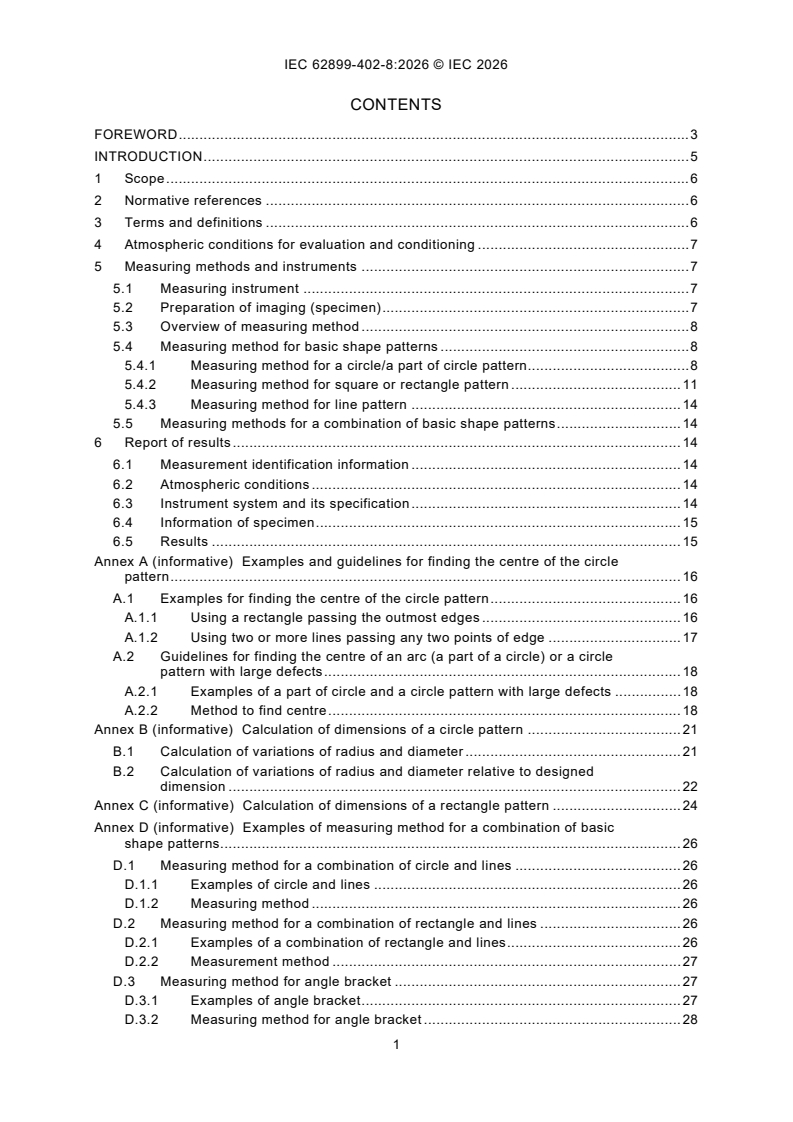
CONTENTS
FOREWORD . 3
INTRODUCTION . 5
1 Scope . 6
2 Normative references . 6
3 Terms and definitions . 6
4 Atmospheric conditions for evaluation and conditioning . 7
5 Measuring methods and instruments . 7
5.1 Measuring instrument . 7
5.2 Preparation of imaging (specimen) . 7
5.3 Overview of measuring method . 8
5.4 Measuring method for basic shape patterns . 8
5.4.1 Measuring method for a circle/a part of circle pattern . 8
5.4.2 Measuring method for square or rectangle pattern . 11
5.4.3 Measuring method for line pattern . 14
5.5 Measuring methods for a combination of basic shape patterns . 14
6 Report of results . 14
6.1 Measurement identification information . 14
6.2 Atmospheric conditions . 14
6.3 Instrument system and its specification . 14
6.4 Information of specimen . 15
6.5 Results . 15
Annex A (informative) Examples and guidelines for finding the centre of the circle
pattern . 16
A.1 Examples for finding the centre of the circle pattern . 16
A.1.1 Using a rectangle passing the outmost edges . 16
A.1.2 Using two or more lines passing any two points of edge . 17
A.2 Guidelines for finding the centre of an arc (a part of a circle) or a circle
pattern with large defects . 18
A.2.1 Examples of a part of circle and a circle pattern with large defects . 18
A.2.2 Method to find centre . 18
Annex B (informative) Calculation of dimensions of a circle pattern . 21
B.1 Calculation of variations of radius and diameter . 21
B.2 Calculation of variations of radius and diameter relative to designed
dimension . 22
Annex C (informative) Calculation of dimensions of a rectangle pattern . 24
Annex D (informative) Examples of measuring method for a combination of basic
shape patterns. 26
D.1 Measuring method for a combination of circle and lines . 26
D.1.1 Examples of circle and lines . 26
D.1.2 Measuring method . 26
D.2 Measuring method for a combination of rectangle and lines . 26
D.2.1 Examples of a combination of rectangle and lines . 26
D.2.2 Measurement method . 27
D.3 Measuring method for angle bracket . 27
D.3.1 Examples of angle bracket . 27
D.3.2 Measuring method for angle bracket . 28
Bibliography . 29
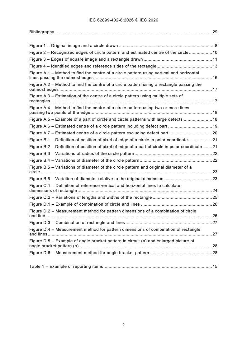
Figure 1 – Original image and a circle drawn . 8
Figure 2 – Recognized edges of circle pattern and estimated centre of the circle . 10
Figure 3 – Edges of square image and a rectangle drawn . 11
Figure 4 – Identified edges and reference sides of the rectangle . 13
Figure A.1 – Method to find the centre of a circle pattern using vertical and horizontal
lines passing the outmost edges . 16
Figure A.2 – Method to find the centre of a circle pattern using a rectangle passing the
outmost edges . 17
Figure A.3 – Estimation of the centre of a circle pattern using multiple sets of
rectangles . 17
Figure A.4 – Method to find the centre of a circle pattern using two or more lines
passing two points of the edge . 18
Figure A.5 – Example of a part of circle and circle patterns with large defects . 18
Figure A.6 – Estimated centre of a circle pattern including defect part . 19
Figure A.7 – Estimated centre of a circle pattern excluding defect part . 20
Figure B.1 – Definition of position of pixel of edge of a circle in polar coordinate . 21
Figure B.2 – Definition of position of pixel of edge of a part of circle in polar coordinate . 21
Figure B.3 – Variations of radius of the circle pattern . 22
Figure B.4 – Variations of diameter of the circle pattern . 22
Figure B.5 – Variations of diameter of the circle pattern and original diameter of a
circle . 23
Figure B.6 – Variation of diameter relative to the original dimension . 23
Figure C.1 – Definition of reference vertical and horizontal lines to calculate
dimensions of rectangle . 24
Figure C.2 – Variations of lengths and widths of the rectangle . 25
Figure D.1 – Example of combination of circle and lines . 26
Figure D.2 – Measurement method for pattern dimensions of a combination of circle
and line. 26
Figure D.3 – Combination of rectangle and lines . 27
Figure D.4 – Measurement method for pattern dimensions of combination of rectangle
and lines . 27
Figure D.5 – Example of angle bracket pattern in circuit (a) and enlarged picture of
angle bracket pattern (b) . 28
Figure D.6 – Measurement method for angle bracket pattern . 28
Table 1 – Example of reporting items . 15
INTERNATIONAL ELECTROTECHNICAL COMMISSION
____________
Printed electronics -
Part 402-8: Printability - Measurement of qualities - Shape pattern
dimension
FOREWORD
1) The International Electrotechnical Commission (IEC) is a worldwide organization for standardization comprising
all national electrotechnical committees (IEC National Committees). The object of IEC is to promote international
co-operation on all questions concerning standardization in the electrical and electronic fields. To this end and
in addition to other activities, IEC publishes International Standards, Technical Specifications, Technical Reports,
Publicly Available Specifications (PAS) and Guides (hereafter referred to as "IEC Publication(s)"). Their
preparation is entrusted to technical committees; any IEC National Committee interested in the subject dealt with
may participate in this preparatory work. International, governmental and non-governmental organizations liaising
with the IEC also participate in this preparation. IEC collaborates closely with the International Organization for
Standardization (ISO) in accordance with conditions determined by agreement between the two organizations.
2) The formal decisions or agreements of IEC on technical matters express, as nearly as possible, an international
consensus of opinion on the relevant subjects since each technical committee has representation from all
interested IEC National Committees.
3) IEC Publications have the form of recommendations for international use and are accepted by IEC National
Committees in that sense. While all reasonable efforts are made to ensure that the technical content of IEC
Publications is accurate, IEC cannot be held responsible for the way in which they are used or for any
misinterpretation by any end user.
4) In order to promote international uniformity, IEC National Committees undertake to apply IEC Publications
transparently to the maximum extent possible in their national and regional publications. Any divergence between
any IEC Publication and the corresponding national or regional publication shall be clearly indicated in the latter.
5) IEC itself does not provide any attestation of conformity. Independent certification bodies provide conformity
assessment services and, in some areas, access to IEC marks of conformity. IEC is not responsible for any
services carried out by independent certification bodies.
6) All users should ensure that they have the latest edition of this publication.
7) No liability shall attach to IEC or its directors, employees, servants or agents including individual experts and
members of its technical committees and IEC National Committees for any personal injury, property damage or
other damage of any nature whatsoever, whether direct or indirect, or for costs (including legal fees) and
expenses arising out of the publication, use of, or reliance upon, this IEC Publication or any other IEC
Publications.
8) Attention is drawn to the Normative references cited in this publication. Use of the referenced publications is
indispensable for the correct application of this publication.
9) IEC draws attention to the possibility that the implementation of this document may involve the use of (a)
patent(s). IEC takes no position concerning the evidence, validity or applicability of any claimed patent rights in
respect thereof. As of the date of publication of this document, IEC had not received notice of (a) patent(s), which
may be required to implement this document. However, implementers are cautioned that this may not represent
the latest information, which may be obtained from the patent database available at https://patents.iec.ch. IEC
shall not be held responsible for identifying any or all such patent rights.
IEC 62899-402-8 has been prepared by IEC technical committee 119: Printed Electronics. It is
an International Standard.
The text of this International Standard is based on the following documents:
Draft Report on voting
119/532/CDV 119/563A/RVC
Full information on the voting for its approval can be found in the report on voting indicated in
the above table.
The language used for the development of this International Standard is English.
This document was drafted in accordance with ISO/IEC Directives, Part 2, and developed in
accordance with ISO/IEC Directives, Part 1 and ISO/IEC Directives, IEC Supplement, available
at www.iec.ch/members_experts/refdocs. The main document types developed by IEC are
described in greater detail at www.iec.ch/publications.
A list of all parts in the IEC 62899 series, published under the general title Printed electronics,
can be found on the IEC website.
The committee has decided that the contents of this document will remain unchanged until the
stability date indicated on the IEC website under webstore.iec.ch in the data related to the
specific document. At this date, the document will be
– reconfirmed,
– withdrawn, or
– revised.
INTRODUCTION
This document specifies the measurement of dimensions of the shape patterns in printed
electronics. The shape patterns include various patterns with shapes such as circle, ellipse,
square, rectangle, etc., as well as a combination of two or more of these, which are commonly
used as parts of printed electronics devices. Various shape patterns constitute printed
electronics devices, and consequently, the printability of patterns including dimension, gain,
loss and distortion affects device performance. Therefore, it is important to measure the
dimensions of shape patterns from the viewpoint of printability.
Some parts of pattern measurement have been specified for line pattern width, edge, and voids
in IEC 62899-402-1, IEC 62899-402-2, and IEC 62899-402-3, respectively. The IEC 62899-403
series includes basic patterns for evaluation of printing machine, basic patterns for plating, etc.,
and moreover, IEC 62899-301-2 deals with the measurement of plate master pattern dimension.
However, there is no standard for the measurement of printed patterns with general shapes.
Therefore, this document is used to measure the dimensions of printed patterns as the result
of the pattern design of the IEC 62899-403 series and plate patterns of IEC 62899-301-2 as
well as to compare the dimensions of printed patterns with the pattern design for evaluating the
printability.
This document includes two methods for the measurement of dimensions of the shape patterns:
The first one is to simply specify the dimension of the shape and compare with the original
design, and the second one is to specify the dimension as well as to quantify the related
attributes such as variation of dimension. For more accurate measurement of dimensions of the
shape patterns, it is recommended to apply the second method which requires the proper
software to recognize the boundaries or edges differentiating the pattern area from the non-
pattern area of the captured image as well as to identify the two-dimensional coordinates of
pixels that constitute the image. This document does not specify the software to recognize the
edge nor the edge detection algorithm. Depending on the user's concern and purpose, the first
method or the second method can be used, or both.
This document excludes the standardization of the measurement system. It specifies the
properties related to the shaped patterns of the printed pattern obtained from the optical
measurement system.
1 Scope
This part of IEC 62899 specifies the measurement methods of the dimensions of the shape
patterns in printed electronics. These printed patterns are treated as two-dimensional on a
substrate. When the patterns are definitely affected by three-dimensional configurations, these
are specified in measurement methods for vertical variance in IEC TR 62899-402-4 in printed
electronics.
NOTE The measurement methods of dimensions of the shape patterns considering three-dimensional
characteristics can be developed later after the measurement methods for vertical variance are established.
2 Normative references
The following documents are referred to in the text in such a way that some or all of their content
constitutes requirements of this document. For dated references, only the edition cited applies.
For undated references, the latest edition of the referenced document (including any
amendments) applies.
ISO 187, Paper, board and pulps - Standard atmosphere for conditioning and testing and
procedure for monitoring the atmosphere and conditioning of samples
ISO 291, Plastics - Standard atmospheres for conditioning and testing
3 Terms and definitions
For the purposes of this document, the following terms and definitions apply.
ISO and IEC maintain terminology databases for use in standardization at the following
addresses:
– IEC Electropedia: available at https://www.electropedia.org/
– ISO Online browsing platform: available at https://www.iso.org/obp
3.1
shape pattern
two-dimensional pattern figure with various shapes
3.2
basic shape pattern
pattern with shapes of circle and rectangle as well as line pattern
3.3
shape pattern dimension
two-dimensional dimension of shape pattern
3.4
reference side
line that best fits each edge of a rectangle
3.5
reference length line
vertical reference side of a rectangle
3.6
reference width line
horizontal reference side of a rectangle
3.7
average length
distance between two reference length lines of a rectangle
3.8
average width
distance between two reference width lines of a rectangle
3.9
region of interest
ROI
area (inside defined boundaries) that the user wants to analyse
[SOURCE: ISO 19262:2015, 3.211]
4 Atmospheric conditions for evaluation and conditioning
The standard atmosphere for evaluation (test and measurement) and storage of the specimen
shall be a temperature of (23 ± 2) °C and relative humidity of (50 ± 10) %, conforming to
standard atmosphere class 2 specified in ISO 291. For a plastic test piece which is a polymer
substrate with printed patterns, the standard atmosphere for evaluation (test and measurement)
and storage of the specimen shall be a temperature of (23 ± 1) °C and relative humidity of
(50 ± 5) %, conforming to standard atmosphere class 1 specified in ISO 291. For a test piece
which is a paper substrate with printed patterns, the standard atmosphere for evaluation (test
and measurement) and storage of the specimen shall be a temperature of (23 ± 1) °C and
relative humidity of (50 ± 2) %, conforming to standard atmosphere specified in ISO 187.
These atmospheric conditions can be changed to give a larger tolerance for temperature
((23 ± 2) °C) and humidity ((50 ± 10) %) by agreement of the consumer and supplier. In this
case, the atmospheric conditions with a larger tolerance shall be reported.
5 Measuring methods and instruments
5.1 Measuring instrument
The measurement of dimensions of the shape pattern shall be carried out with an instrument
that can obtain the image of patterns. The repeatability and accuracy of the measuring
instrument should be less than 10 % of the tolerance specification of the pattern dimension.
From the measurement system, the image of the pattern should be converted to an image file.
The image should include the information of pixel size as well as image size converted to an
image file.
5.2 Preparation of imaging (specimen)
The specimen for measuring dimensions of the shape pattern shall be prepared as the original
image file from the measuring instrument without re-sizing and cropping and shall contain the
whole image of the pattern to be measured. The measurer should report the resolution of the
measurement system and pixel size of the image.
5.3 Overview of measuring method
Depending on the shape of the pattern, the steps to specify the dimensions should differ. The
steps for each shape pattern are shown in 5.4 and 5.5. Subclause 5.4 describes the
measurement methods for circle, rectangle, and line pattern as basic patterns, and 5.5 deals
with the examples of a combination of patterns of circles, rectangles and lines as indicated in
Annex D. Each measurement step for circle and rectangle is divided into two parts. The first
part (simple measurement) is to simply specify the dimension of the shape and compare with
the original design, and the second part (advanced measurement) is to specify the dimension
as well as to quantify the related attributes such as variation of dimension. Depending on the
user's concern and purpose, simple measurement or advanced measurement, or both, can be
used. For more accurate measurement of dimensions of the shape patterns, or for advanced
measurement, proper software is required to recognize the boundaries or edges differentiating
the pattern area from the non-pattern area of the captured image as well as to identify the two-
dimensional coordinates of pixels that constitute the image. This document does not specify the
software to recognize the edge nor the edge detection algorithm, but the edge detection
algorithm used should be reported. More information on the edge detection algorithm or other
information related to software should be reported as well on the request of custome
...