

IEC TR 62786-101:2026
(Main)Distributed energy resources connection with the grid - Part 101: Gravity storage connection to the grid
- Abstract
IEC TR 62786-101:2026 provides the principles and general technical characteristics of gravity energy storage systems (GESS) connected to the distribution network. It provides a reference for the planning, design, grid connection and operation of GESS. It includes an introduction to GESS, grid-connection methods, grid-connected characteristics, grid-connected operation and grid-connected testing and so on.
GESS can use liquid or solid mediums for storing or releasing energy. For example, traditional pumped storage utilizes liquid water to achieve energy storing or releasing. This document only focuses on the solid GESS, which utilize solid materials (such as concrete, slag, construction waste, etc.) for energy storage. Generally, GESS can be classified as vertical GESS and slope GESS. In the GESS, the motor-generators (MG) that are directly connected, or indirectly connected to the low voltage (LV) or medium voltage (MV) distribution network through converters, transfer the energy between the mass blocks and the grid. This document reports the grid-connection method, active power response characteristic, response of active power to frequency, response of reactive power to voltage and test of direct grid connection through synchronous motor-generator (SMG), as a supplement to IEC TS 62786-1:2023.
This document describes the interface arrangement for the connection of GESS to distribution networks with the nominal frequency of 50 Hz or 60 Hz.
- Status
- Published
- Publication Date
- 07-Oct-2026
- Technical Committee
- TC 8 - System aspects of electrical energy supply
- Drafting Committee
- JWG 10 - TC 8/JWG 10
- Current Stage
- PPUB - Publication issued
- Start Date
- 08-Oct-2026
- Completion Date
- 09-Oct-2026

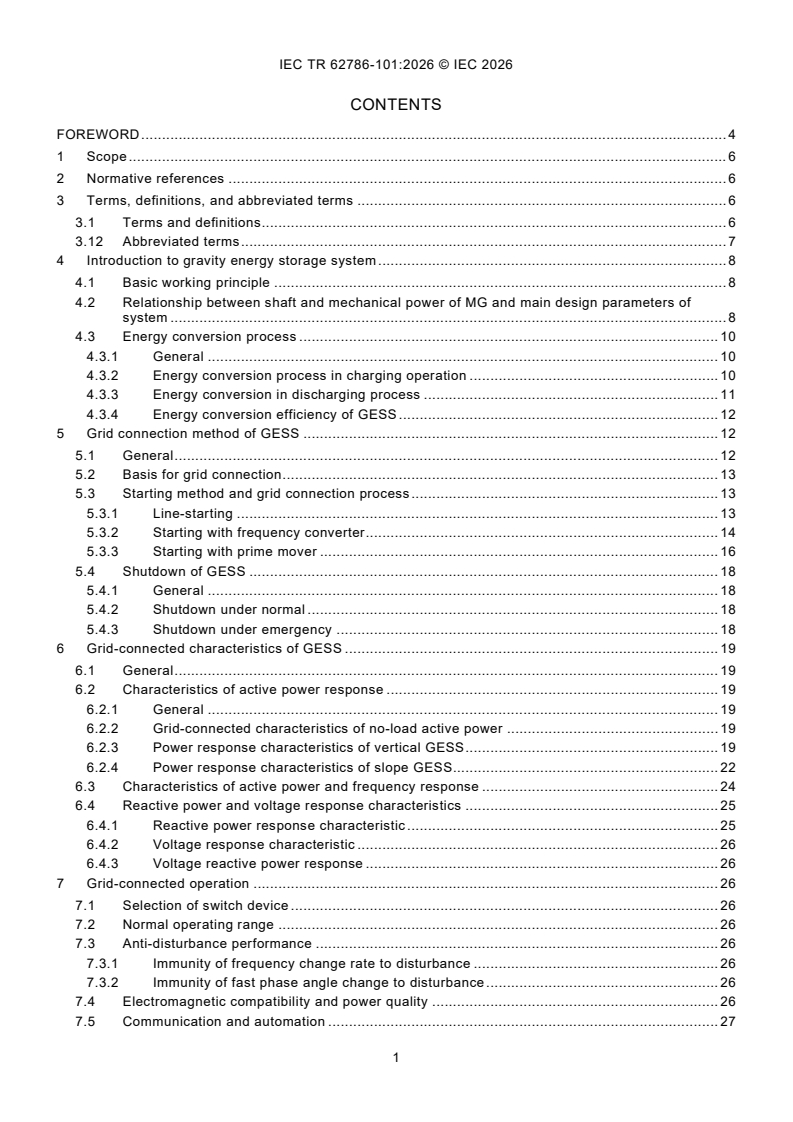
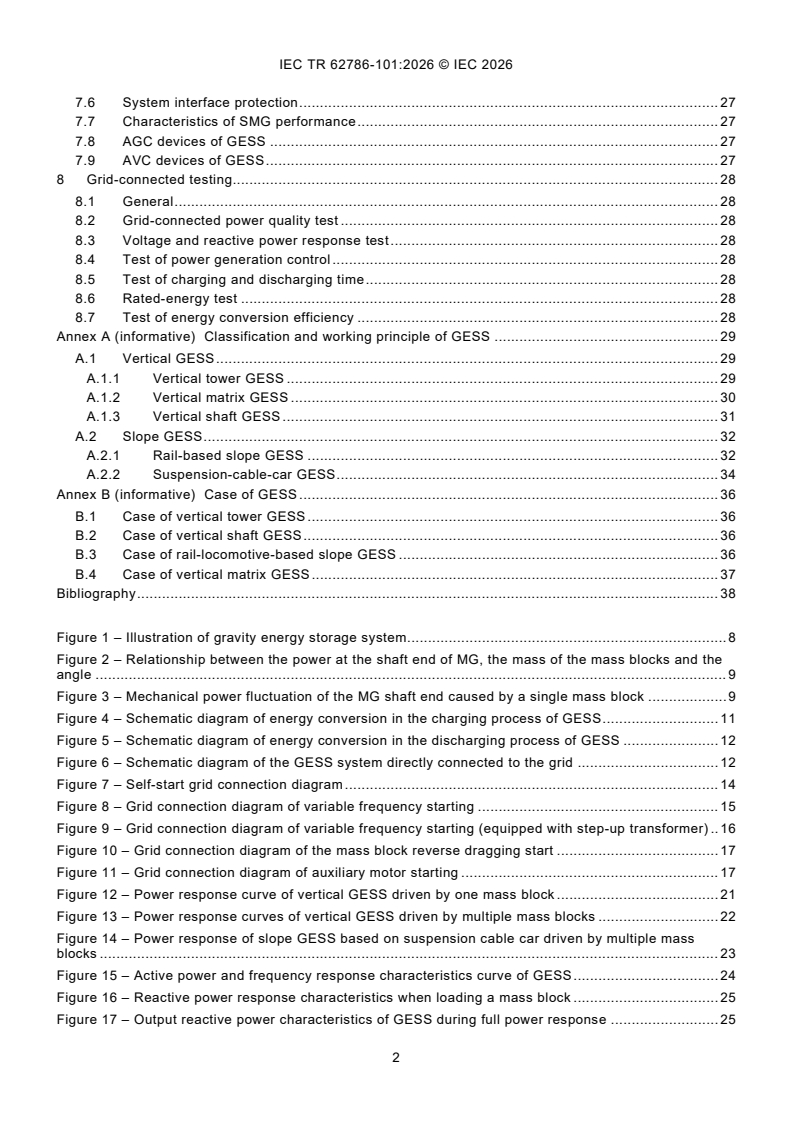
IEC TR 62786-101:2026, published by IEC, gives the principles and general technical characteristics of gravity energy storage systems (GESS) connected to distribution networks. It is written for planning, design, grid connection and operation of solid GESS, and it also covers grid-connected characteristics and testing for systems on 50 Hz or 60 Hz networks.
What does IEC TR 62786-101:2026 specify?
IEC TR 62786-101:2026 is a technical report on gravity storage connection to the grid. It focuses on solid GESS that use mass blocks such as concrete, slag or construction waste, and on the way those systems interact with low voltage (LV) and medium voltage (MV) distribution networks through motor-generators (MG).
The document is organized into:
- Clause 1 - scope
- Clause 2 - normative references
- Clause 3 - terms, definitions and abbreviated terms
- Clause 4 - introduction and working principle
- Clause 5 - grid connection method
- Clause 6 - grid-connected characteristics
- Clause 7 - grid-connected operation
- Clause 8 - grid-connected testing
- Annex A and Annex B, both informative
| Annex | What it covers |
|---|---|
| Annex A | Classification and working principle of GESS, including vertical GESS and slope GESS and their subtypes |
| Annex B | Example cases of vertical tower, vertical shaft, rail-locomotive-based slope and vertical matrix GESS |
In practice, this structure helps a reader move from system concepts to connection, operation and test methods without needing to search through separate documents.
What are the key requirements of IEC TR 62786-101:2026?
IEC TR 62786-101:2026 describes how a GESS should be connected, started, controlled, shut down and tested. The most important point is that the report treats GESS as a grid-connected electrical and mechanical system, so the electrical interface and the moving mass blocks have to be considered together.
How does IEC TR 62786-101:2026 describe charging and discharging?
Clause 4 explains the basic working principle of GESS. During charging, the MG works in motoring mode and lifts the mass block, converting electrical energy into gravity potential energy. During discharging, the falling mass block drives the MG in generating mode and sends electrical energy back to the grid.
For engineers, this means the storage capacity, response and losses depend not only on electrical ratings but also on the height, mass, motion path and mechanical transmission. Clause 4 also shows that the mechanical transmission can use devices such as gearboxes, sprockets, belt pulleys, steel cables, chains or belts.
How does IEC TR 62786-101:2026 handle grid connection?
Clause 5 says direct grid connection through the synchronous motor-generator (SMG) requires phase sequence, phase angle, magnitude and frequency to match the grid. Synchronization can be manual or automatic, and the report recommends making the SMG frequency and phase slightly ahead of the grid at the closing instant so that active power flows immediately after connection.
Clause 5 also describes protective measures such as synchronism-check relays, protection relays, overspeed protection and safety interlocks. In practice, this means a project team must verify not only the electrical match but also the safety logic before the breaker closes.
Which starting and shutdown methods are covered?
Clause 5.3 describes several starting methods:
- line-starting
- starting with a frequency converter
- starting with a frequency converter and step-up transformer
- mass-block reverse traction starting
- auxiliary motor starting
Each method uses a different sequence of breaker operations, excitation control and speed ramping. That matters because the start method changes equipment selection, control logic and the expected inrush or transient behaviour.
Clause 5.4 covers shutdown in normal and emergency conditions. It includes disabling AGC and AVC, disconnecting the mechanical link, opening the SMG circuit breaker, de-exciting the machine and applying braking devices. In an emergency, the report gives separate actions for a faulty mass block working unit, an SMG fault and a power supply line fault.
What operating behaviour does IEC TR 62786-101:2026 describe?
Clause 6 explains active power response, frequency response, reactive power response and voltage response. The report shows that GESS can provide step-like active power changes because mass blocks are discrete, and that the response depends on whether the system is vertical or slope-based.
For frequency support, the report says a GESS connected to LV and MV grids can change the number of online mass blocks to follow frequency deviation. For voltage support, it says the system can operate with power factor, reactive power or voltage control and can also act like a synchronous condenser when no load is present. In practice, this is why GESS can be used for short-term power balancing and voltage support, not just energy shifting.
What does IEC TR 62786-101:2026 say about testing?
Clause 8 covers grid-connected power quality tests, voltage and reactive power response tests, power generation control tests, charging and discharging time tests, rated-energy tests and energy conversion efficiency tests. The report also notes that high- or low-voltage ride-through testing is not required for the directly connected SMG arrangement described here.
What terms does IEC TR 62786-101:2026 define?
- Gravity energy storage system (GESS) - a system that stores and releases electrical energy by moving mass blocks up and down through the power system.
- Motor-generator (MG) - the electrical machine in the GESS that operates either as a motor or as a generator.
- Synchronous motor-generator (SMG) - the SMG used for direct grid connection and synchronization with the distribution network.
- Automatic generation control (AGC) - the control function that adjusts active power output and can start or stop units according to dispatch needs.
- Automatic voltage control (AVC) - the control function that adjusts reactive power and voltage according to dispatch needs.
- Mass block working unit - the minimum equipment set that can run independently, including the mass block, transmission device, carrier, auxiliary electrical equipment and control device.
- Hot standby status - the state where the SMG is already started and connected, and the mass block is ready for immediate charging or discharging.
Who uses IEC TR 62786-101:2026?
IEC TR 62786-101:2026 is used by grid connection engineers, system designers, project developers, equipment suppliers, utility operators and testing teams working on gravity storage projects. It is relevant to planning and operation of GESS on distribution networks, especially where a project must coordinate electrical protection, synchronization, communication and dispatch control.
It is also useful for quality managers and buyers who need to compare GESS proposals or check whether a design includes the functions expected for grid interconnection, control and testing.
Which standards are used with IEC TR 62786-101:2026?
IEC TR 62786-101:2026 refers to several IEC and ISO publications for related technical functions:
- IEC TS 62786-1:2023 - companion part for switch device selection, operating range, disturbance immunity and protection
- IEC 60255-1:2022 - measuring relays and protection equipment
- IEC 60034-1:2022, IEC 60034-7:2020, IEC 60034-5:2020 and IEC 60034-6:1991 - rotating machine rating, construction, enclosure protection and cooling
- IEC 61850-7-420:2021 - communication and automation for distributed energy resources
- IEC 60038:2009 and IEC 60071-1:2019 - standard voltages and insulation co-ordination
- IEC 62305-3:2024, IEC 62561-1:2023 and IEC 62561-5:2023 - lightning protection and earthing components
- IEC 61000-6-5:2015 and IEC TS 62749:2020 - EMC and power quality
- IEC TS 62933-3-1:2018 and IEC 62933-2-1:2017 - storage-system planning, performance assessment and testing
- IEC 61000-4-30:2015 - power quality measurement methods
- ISO 7010:2019 and ISO 7010:2019/Amd 7:2023 - safety signs
What does the IEC TR 62786-101:2026 document contain?
The document contains working-principle figures, connection diagrams, start-up and shutdown sequences, response curves, and test items for power quality, reactive power, power control, timing, rated energy and efficiency. It also includes formulas for mechanical power, energy conversion and frequency response, plus tables for frequency and voltage response.
Annex A gives classified examples of vertical and slope GESS, including tower, matrix, shaft, rail-locomotive, chain-rail, cable-rail and suspension-cable-car forms. Annex B gives example projects and case descriptions that show how the concepts are implemented in practice.
Get Certified
Connect with accredited certification bodies for this standard

DIBt (Deutsches Institut für Bautechnik)
German Institute for Building Technology.
DIN CERTCO
DIN Group product certification.

IMQ S.p.A. (Certification)
Italian electrical product certification.
Sponsored listings
Frequently Asked Questions
IEC TR 62786-101:2026 is a technical report published by the International Electrotechnical Commission (IEC). Its full title is "Distributed energy resources connection with the grid - Part 101: Gravity storage connection to the grid". This standard covers: IEC TR 62786-101:2026 provides the principles and general technical characteristics of gravity energy storage systems (GESS) connected to the distribution network. It provides a reference for the planning, design, grid connection and operation of GESS. It includes an introduction to GESS, grid-connection methods, grid-connected characteristics, grid-connected operation and grid-connected testing and so on. GESS can use liquid or solid mediums for storing or releasing energy. For example, traditional pumped storage utilizes liquid water to achieve energy storing or releasing. This document only focuses on the solid GESS, which utilize solid materials (such as concrete, slag, construction waste, etc.) for energy storage. Generally, GESS can be classified as vertical GESS and slope GESS. In the GESS, the motor-generators (MG) that are directly connected, or indirectly connected to the low voltage (LV) or medium voltage (MV) distribution network through converters, transfer the energy between the mass blocks and the grid. This document reports the grid-connection method, active power response characteristic, response of active power to frequency, response of reactive power to voltage and test of direct grid connection through synchronous motor-generator (SMG), as a supplement to IEC TS 62786-1:2023. This document describes the interface arrangement for the connection of GESS to distribution networks with the nominal frequency of 50 Hz or 60 Hz.
IEC TR 62786-101:2026 provides the principles and general technical characteristics of gravity energy storage systems (GESS) connected to the distribution network. It provides a reference for the planning, design, grid connection and operation of GESS. It includes an introduction to GESS, grid-connection methods, grid-connected characteristics, grid-connected operation and grid-connected testing and so on. GESS can use liquid or solid mediums for storing or releasing energy. For example, traditional pumped storage utilizes liquid water to achieve energy storing or releasing. This document only focuses on the solid GESS, which utilize solid materials (such as concrete, slag, construction waste, etc.) for energy storage. Generally, GESS can be classified as vertical GESS and slope GESS. In the GESS, the motor-generators (MG) that are directly connected, or indirectly connected to the low voltage (LV) or medium voltage (MV) distribution network through converters, transfer the energy between the mass blocks and the grid. This document reports the grid-connection method, active power response characteristic, response of active power to frequency, response of reactive power to voltage and test of direct grid connection through synchronous motor-generator (SMG), as a supplement to IEC TS 62786-1:2023. This document describes the interface arrangement for the connection of GESS to distribution networks with the nominal frequency of 50 Hz or 60 Hz.
IEC TR 62786-101:2026 is classified under the following ICS (International Classification for Standards) categories: 29.240.01 - Power transmission and distribution networks in general; 91.140.50 - Electricity supply systems. The ICS classification helps identify the subject area and facilitates finding related standards.
IEC TR 62786-101:2026 is available in PDF format for immediate download after purchase. The document can be added to your cart and obtained through the secure checkout process. Digital delivery ensures instant access to the complete standard document.
Standards Content (Sample)
IEC TR 62786-101 ®
Edition 1.0 2026-10
TECHNICAL
REPORT
Distributed energy resources connection with the grid -
Part 101: Gravity storage connection to the grid
ICS 29.240.01; 91.140.50 ISBN 978-2-8327-1497-3
All rights reserved. Unless otherwise specified, no part of this publication may be reproduced or utilized in any form or
by any means, electronic or mechanical, including photocopying and microfilm, without permission in writing from either
IEC or IEC's member National Committee in the country of the requester. If you have any questions about IEC copyright
or have an enquiry about obtaining additional rights to this publication, please contact the address below or your local
IEC member National Committee for further information.
IEC Secretariat Tel.: +41 22 919 02 11
3, rue de Varembé info@iec.ch
CH-1211 Geneva 20 www.iec.ch
Switzerland
About the IEC
The International Electrotechnical Commission (IEC) is the leading global organization that prepares and publishes
International Standards for all electrical, electronic and related technologies.
About IEC publications
The technical content of IEC publications is kept under constant review by the IEC. Please make sure that you have the
latest edition, a corrigendum or an amendment might have been published.
IEC publications search - IEC Products & Services Portal - products.iec.ch
webstore.iec.ch/advsearchform Discover our powerful search engine and read freely all the
The advanced search enables to find IEC publications by a publications previews, graphical symbols and the glossary.
variety of criteria (reference number, text, technical With a subscription you will always have access to up to date
committee, …). It also gives information on projects, content tailored to your needs.
replaced and withdrawn publications.
Electropedia - www.electropedia.org
The world's leading online dictionary on electrotechnology,
IEC Just Published - webstore.iec.ch/justpublished
Stay up to date on all new IEC publications. Just Published containing more than 22 500 terminological entries in English
details all new publications released. Available online and and French, with equivalent terms in 25 additional languages.
once a month by email. Also known as the International Electrotechnical Vocabulary
(IEV) online.
IEC Customer Service Centre - webstore.iec.ch/csc
If you wish to give us your feedback on this publication or
need further assistance, please contact the Customer
Service Centre: sales@iec.ch.
CONTENTS
FOREWORD . 4
1 Scope . 6
2 Normative references . 6
3 Terms, definitions, and abbreviated terms . 6
3.1 Terms and definitions . 6
3.12 Abbreviated terms . 7
4 Introduction to gravity energy storage system . 8
4.1 Basic working principle . 8
4.2 Relationship between shaft and mechanical power of MG and main design parameters of
system . 8
4.3 Energy conversion process . 10
4.3.1 General . 10
4.3.2 Energy conversion process in charging operation . 10
4.3.3 Energy conversion in discharging process . 11
4.3.4 Energy conversion efficiency of GESS . 12
5 Grid connection method of GESS . 12
5.1 General . 12
5.2 Basis for grid connection . 13
5.3 Starting method and grid connection process . 13
5.3.1 Line-starting . 13
5.3.2 Starting with frequency converter . 14
5.3.3 Starting with prime mover . 16
5.4 Shutdown of GESS . 18
5.4.1 General . 18
5.4.2 Shutdown under normal . 18
5.4.3 Shutdown under emergency . 18
6 Grid-connected characteristics of GESS . 19
6.1 General . 19
6.2 Characteristics of active power response . 19
6.2.1 General . 19
6.2.2 Grid-connected characteristics of no-load active power . 19
6.2.3 Power response characteristics of vertical GESS . 19
6.2.4 Power response characteristics of slope GESS . 22
6.3 Characteristics of active power and frequency response . 24
6.4 Reactive power and voltage response characteristics . 25
6.4.1 Reactive power response characteristic . 25
6.4.2 Voltage response characteristic . 26
6.4.3 Voltage reactive power response . 26
7 Grid-connected operation . 26
7.1 Selection of switch device . 26
7.2 Normal operating range . 26
7.3 Anti-disturbance performance . 26
7.3.1 Immunity of frequency change rate to disturbance . 26
7.3.2 Immunity of fast phase angle change to disturbance . 26
7.4 Electromagnetic compatibility and power quality . 26
7.5 Communication and automation . 27
7.6 System interface protection . 27
7.7 Characteristics of SMG performance . 27
7.8 AGC devices of GESS . 27
7.9 AVC devices of GESS . 27
8 Grid-connected testing. 28
8.1 General . 28
8.2 Grid-connected power quality test . 28
8.3 Voltage and reactive power response test . 28
8.4 Test of power generation control . 28
8.5 Test of charging and discharging time . 28
8.6 Rated-energy test . 28
8.7 Test of energy conversion efficiency . 28
Annex A (informative) Classification and working principle of GESS . 29
A.1 Vertical GESS . 29
A.1.1 Vertical tower GESS . 29
A.1.2 Vertical matrix GESS . 30
A.1.3 Vertical shaft GESS . 31
A.2 Slope GESS . 32
A.2.1 Rail-based slope GESS . 32
A.2.2 Suspension-cable-car GESS . 34
Annex B (informative) Case of GESS . 36
B.1 Case of vertical tower GESS . 36
B.2 Case of vertical shaft GESS . 36
B.3 Case of rail-locomotive-based slope GESS . 36
B.4 Case of vertical matrix GESS . 37
Bibliography . 38
Figure 1 – Illustration of gravity energy storage system . 8
Figure 2 – Relationship between the power at the shaft end of MG, the mass of the mass blocks and the
angle . 9
Figure 3 – Mechanical power fluctuation of the MG shaft end caused by a single mass block . 9
Figure 4 – Schematic diagram of energy conversion in the charging process of GESS . 11
Figure 5 – Schematic diagram of energy conversion in the discharging process of GESS . 12
Figure 6 – Schematic diagram of the GESS system directly connected to the grid . 12
Figure 7 – Self-start grid connection diagram . 14
Figure 8 – Grid connection diagram of variable frequency starting . 15
Figure 9 – Grid connection diagram of variable frequency starting (equipped with step-up transformer) . 16
Figure 10 – Grid connection diagram of the mass block reverse dragging start . 17
Figure 11 – Grid connection diagram of auxiliary motor starting . 17
Figure 12 – Power response curve of vertical GESS driven by one mass block . 21
Figure 13 – Power response curves of vertical GESS driven by multiple mass blocks . 22
Figure 14 – Power response of slope GESS based on suspension cable car driven by multiple mass
blocks . 23
Figure 15 – Active power and frequency response characteristics curve of GESS . 24
Figure 16 – Reactive power response characteristics when loading a mass block . 25
Figure 17 – Output reactive power characteristics of GESS during full power response . 25
Figure A.1 – Structure of vertical tower GESS . 29
Figure A.2 – Charging and discharging processes of vertical tower GESS . 30
Figure A.3 – Vertical matrix GESS . 31
Figure A.4 – Vertical shaft GESS . 32
Figure A.5 – Rail-locomotive-based slope GESS . 32
Figure A.6 – Chain-rail-based slope GESS. 33
Figure A.7 – Cable-rail-based slope GESS. 34
Figure A.8 – Suspension-cable-car GESS . 34
Figure B.1 – Vertical matrix GESS . 37
Table 1 – Frequency response of GESS . 24
Table 2 – Response of GESS to voltage variation . 26
INTERNATIONAL ELECTROTECHNICAL COMMISSION
____________
Distributed energy resources connection with the grid -
Part 101: Gravity storage connection to the grid
FOREWORD
1) The International Electrotechnical Commission (IEC) is a worldwide organization for standardization comprising all national
electrotechnical committees (IEC National Committees). The object of IEC is to promote international co-operation on all
questions concerning standardization in the electrical and electronic fields. To this end and in addition to other activities, IEC
publishes International Standards, Technical Specifications, Technical Reports, Publicly Available Specifications (PAS) and
Guides (hereafter referred to as "IEC Publication(s)"). Their preparation is entrusted to technical committees; any IEC National
Committee interested in the subject dealt with may participate in this preparatory work. International, governmental and non-
governmental organizations liaising with the IEC also participate in this preparation. IEC collaborates closely with the
International Organization for Standardization (ISO) in accordance with conditions determined by agreement between the two
organizations.
2) The formal decisions or agreements of IEC on technical matters express, as nearly as possible, an international consensus of
opinion on the relevant subjects since each technical committee has representation from all interested IEC National Committees.
3) IEC Publications have the form of recommendations for international use and are accepted by IEC National Committees in that
sense. While all reasonable efforts are made to ensure that the technical content of IEC Publications is accurate, IEC cannot
be held responsible for the way in which they are used or for any misinterpretation by any end user.
4) In order to promote international uniformity, IEC National Committees undertake to apply IEC Publications transparently to the
maximum extent possible in their national and regional publications. Any divergence between any IEC Publication and the
corresponding national or regional publication shall be clearly indicated in the latter.
5) IEC itself does not provide any attestation of conformity. Independent certification bodies provide conformity assessment services
and, in some areas, access to IEC marks of conformity. IEC is not responsible for any services carried out by independent
certification bodies.
6) All users should ensure that they have the latest edition of this publication.
7) No liability shall attach to IEC or its directors, employees, servants or agents including individual experts and members of its
technical committees and IEC National Committees for any personal injury, property damage or other damage of any nature
whatsoever, whether direct or indirect, or for costs (including legal fees) and expenses arising out of the publication, use of, or
reliance upon, this IEC Publication or any other IEC Publications.
8) Attention is drawn to the Normative references cited in this publication. Use of the referenced publications is indispensable for
the correct application of this publication.
9) IEC draws attention to the possibility that the implementation of this document may involve the use of (a) patent(s). IEC takes
no position concerning the evidence, validity or applicability of any claimed patent rights in respect thereof. As of the date of
publication of this document, IEC had not received notice of (a) patent(s), which may be required to implement this document.
However, implementers are cautioned that this may not represent the latest information, which may be obtained from the patent
database available at https://patents.iec.ch. IEC shall not be held responsible for identifying any or all such patent rights.
IEC TR 62786-101 has been prepared by IEC Technical Committee 8: System aspects of electrical energy
supply. It is a Technical Report.
The text of this Technical Report is based on the following documents:
Draft Report on voting
8/1814/DTR 8/1832/RVDTR
Full information on the voting for its approval can be found in the report on voting indicated in the above
table.
The language used for the development of this Technical Report is English.
A list of all parts in the IEC 62786 series, published under the general title Distributed energy resources
connection with the grid, can be found on the IEC website.
This document was drafted in accordance with ISO/IEC Directives, Part 2, and developed in accordance
with ISO/IEC Directives, Part 1 and ISO/IEC Directives, IEC Supplement, available at
www.iec.ch/members_experts/refdocs. The main document types developed by IEC are described in
greater detail at www.iec.ch/publications.
The committee has decided that the contents of this document will remain unchanged until the stability date
indicated on the IEC website under webstore.iec.ch in the data related to the specific document. At this
date, the document will be
– reconfirmed,
– withdrawn, or
– revised.
1 Scope
This part of IEC TS 62786, which is a Technical Report, provides the principles and general technical
characteristics of gravity energy storage systems (GESS) connected to the distribution network. It provides
a reference for the planning, design, grid connection and operation of GESS. It includes an introduction to
GESS, grid-connection methods, grid-connected characteristics, grid-connected operation and grid-
connected testing and so on.
GESS can use liquid or solid mediums for storing or releasing energy. For example, traditional pumped
storage utilizes liquid water to achieve energy storing or releasing. This document only focuses on the solid
GESS, which utilize solid materials (such as concrete, slag, construction waste, etc.) for energy storage.
Generally, GESS can be classified as vertical GESS and slope GESS. In the GESS, the motor-generators
(MG) that are directly connected, or indirectly connected to the low voltage (LV) or medium voltage (MV)
distribution network through converters, transfer the energy between the mass blocks and the grid. This
document reports the grid-connection method, active power response characteristic, response of active
power to frequency, response of reactive power to voltage and test of direct grid connection through
synchronous motor-generator (SMG), as a supplement to IEC TS 62786-1:2023 [1].
This document describes the interface arrangement for the connection of GESS to distribution networks
with the nominal frequency of 50 Hz or 60 Hz.
2 Normative references
There are no normative references in this document.
3 Terms, definitions, and abbreviated terms
3.1 Terms and definitions
For the purposes of this document, the following terms and definitions apply.
ISO and IEC maintain terminology databases for use in standardization at the following addresses:
– IEC Electropedia: available at https://www.electropedia.org/
– ISO Online browsing platform: available at https://www.iso.org/obp
3.2
gravity energy storage system
system using mass block as energy storage medium, absorbing, storing, converting and releasing electrical
energy through power system, generally including motor-generator (MG), mass block, mechanical
transmission device, mass block carrier device, mass block stacking device, auxiliary electrical equipment
and control device, and so on
Note 1 to entry: The GESS of various structures use different mechanical devices to lift the mass blocks. In this document, GESS
are generally classified into vertical GESS and slope GESS, by the moving paths of the mass blocks. A GESS is called a single-
machine system if it contains only one MG, and a multi-machine system if it contains multiple MG.
3.3
motor-generator
electrical machine for GESS that can be operated in motoring mode or generating mode
3.4
motoring mode
operating mode in which the motor-generator machine operates as a motor to lift the mass block from a
lower position to a higher position
3.5
generating mode
operating mode in which the motor-generator machine operates as a generator while the mass block is
lowered from a higher position to a lower position
3.6
mass block working unit
minimum combination of equipment that can execute the independent operation for the GESS, generally
including the mass block, mechanical transmission device, mass block carrier, auxiliary electrical equipment
and control device
Note 1 to entry: The motor-generator in a GESS can be loaded with one or more mass blocks work units.
3.7
mass block
solid material that stores and releases energy through its height change
3.8
mass block stacking site
site for stacking mass blocks typically containing the high potential energy storage site and the low potential
energy stacking site
3.9
mechanical transmission device
mechanical component for connecting mass blocks to the motor-generator, including the drag device and
the speed change device
3.10
mass block carrier
device for carrying mass blocks during up and down operation of the mass block
3.11
hot standby status
state in which the motor-generator has completed the start-up process and is connected to the grid, the
mass block being in a position to be put into operation immediately when the system receives a charging
or discharging instruction
3.12 Abbreviated terms
AGC automatic generation control
AVC automatic voltage control
EMC electromagnetic compatibility
GESS gravity energy storage system
LV low voltage
MV medium voltage
MG motor-generator
POC point of connection
SMG synchronous motor-generator
4 Introduction to gravity energy storage system
4.1 Basic working principle
At the time of writing, the GESS has different types of structure. It can be classified into the vertical type
and the slope type according to the moving trajectory of the mass block, as detailed in Annex A. In the
GESS, the electricity can be stored and released by the mass blocks that are held in higher and lower
positions, with different gravity potential energy. In the charging operation, the MG of GESS works in
motoring mode, absorbing the active power from the power grid. This electric energy is used to lift the mass
block from the lower position to the higher position via a mechanical transmission device, effectively
converted into the gravity potential energy. In the discharging operation, the mass block that falls from the
higher position to the lower position drives the MG to generate electrical power through the mechanical
transmission device. The MG in this generating mode converts the gravity potential energy of the mass
block into the electricity, and sends it back to the grid. The mechanical transmission device transforms the
linear motion of the mass block into the rotational motion of the MG shaft, and it is composed of a speed
change device and a driving device. According to existing GESS cases (Annex B), a gearbox, sprocket,
belt pulley or other equipment can be chosen as the speed change device, and a steel cable, chain or belt
can be chosen as the driving device, as shown in Figure 1. These speed change and driving devices are
selected and finalized during the initial design phase of the GESS structure.
Figure 1 – Illustration of gravity energy storage system
4.2 Relationship between shaft and mechanical power of MG and main design parameters of
system
During the operation of GESS, the speed of the mass block in the steady state is fixed, and the input power
to the MG from its mechanical section is given by Formula (1).
𝑃𝑃 =𝜂𝜂 𝑛𝑛𝑛𝑛𝑛𝑛𝑛𝑛sin(𝜃𝜃) (1)
se m
where
P
is the power provided to the MG by the mechanical section,
se
η
is the total efficiency of the mechanical transmission device,
m
n
is the number of mass blocks moving between the higher position and
the lower position,
m
is the mass of a single mass block,
g
is the gravity acceleration,
v
is the constant velocity of the mass block,
θ
is the angle between the path of the mass block and the horizontal
plane.
According to Formula (1), with the given speed and the number of mass blocks, the relationship between
the input power to the shaft end of the MG, the mass of the mass blocks and the angle is shown in Figure 2.
Figure 2 – Relationship between the power at the shaft end of MG, the mass of the mass blocks
and the angle
According to Formula (1) and Figure 2, when the angle is fixed, the mechanical power at the shaft end of
the MG is proportional to the mass of the mass blocks. When the number of mass blocks is fixed, the power
is proportional to the mass of a single mass block. Because the mass of a single mass block in the system
is constant, the power has a sinusoidal relationship with the angle.
When two GESS have the same P , the same total mass but different numbers (n and n , 𝑛𝑛 >𝑛𝑛 ) of the
2 1
se 1 2
mass blocks moving between the higher position and the lower position, the mechanical power fluctuation
caused by a single mass block in the charging and discharging processes is shown in Figure 3.
Figure 3 – Mechanical power fluctuation of the MG shaft end caused by a single mass block
According to Figure 3, n affects the percentage of the power fluctuation caused by the switching of a single
mass block. It can be observed that as n increases, the power fluctuation of a single mass block decreases
( 𝛥𝛥𝑃𝑃 <𝛥𝛥𝑃𝑃 ).
se−𝑛𝑛2 se−𝑛𝑛1
4.3 Energy conversion process
4.3.1 General
Despite the various structural forms, all the GESS rely on the MG to convert the electric active power to
the gravity potential energy and vice versa. The following focus on the GESS that is directly connected to
the grid through the SMG, and the processes of charging and discharging are also described. The reactive
power can flow between the grid and GESS due to the exciter system of the SMG.
4.3.2 Energy conversion process in charging operation
The energy conversion during the charging process of GESS is shown in Figure 4. The SMG absorbs
electric active power from the grid and drives the mass block upward at the rated speed. With the increase
of the height of the mass block, the electric active power is gradually converted into the gravity potential
energy of the mass block. The expressions of the kinetic energy and gravity potential energy of the mass
block are given by Formula (2) and Formula (3).
𝑁𝑁
𝐸𝐸 = �𝑛𝑛𝑛𝑛 (2)
k 𝑖𝑖 𝑖𝑖
𝑖𝑖=1
where
E
is the total kinetic energy of all the mass blocks in the GESS during
k
up and down operations,
N
is the total number of mass blocks in the system,
th
m
is the mass of the i mass block,
i
th
v is the constant velocity of the i mass block along the rail,
i
𝑁𝑁
𝐸𝐸 =�𝑛𝑛𝑛𝑛ℎ (3)
p 𝑖𝑖 𝑖𝑖
𝑖𝑖=1
where
E
is the total gravity potential energy stored in the system,
p
N
is the total number of mass blocks in the system,
th
m
is the mass of the i mass block,
i
g
is the gravity acceleration,
th
h
is the moving height of the i mass block.
i
When the GESS is operating, most of the electric energy absorbed by the SMG from the grid is transformed
into mechanical energy, including both the gravitational potential energy and the kinetic energy. If the
system has no kinetic energy recovery device, this kinetic energy ultimately dissipates into various forms,
e.g. as heat. Additionally, energy losses occur within the electrical and mechanical sections, including the
copper losses, iron losses, and mechanical friction. Furthermore, energy is required to transport the mass
block in the high- and low-potential energy stacking site.
The total electric energy absorbed by the GESS from the grid is given by Formula (4):
𝐸𝐸 =𝐸𝐸 +𝐸𝐸 +𝐸𝐸 +𝐸𝐸 +𝐸𝐸 (4)
charge p k ef mf t
where
E
is the total electric energy absorbed by the GESS during the charging
charge
process,
E
is the total energy loss of the electrical section,
ef
E
is the total energy loss of the mechanical section,
mf
E
is the total electric energy consumed by the mass block during the
t
transportation process in the high- and low-potential energy stacking
sites.
Figure 4 – Schematic diagram of energy conversion in the charging process of GESS
4.3.3 Energy conversion in discharging process
The energy conversion in the discharging process of the GESS is shown in Figure 5. The system releases
the mass block from the high-potential energy stacking site. As the position of the mass block is being
lowered, its gravity potential energy is gradually converted into kinetic energy and fed back to the grid as
electric energy.
When the mass block moves to the lowest potential energy position and reaches a state of rest, its kinetic
energy is reduced to zero and is considered a loss term here (assuming no kinetic energy recovery device).
The total electric energy generated by the GESS and fed back to the grid is given by Formula (5).
𝐸𝐸 =𝐸𝐸 −𝐸𝐸 −𝐸𝐸 −𝐸𝐸 −𝐸𝐸 (5)
discharge p k ef mf t
where
E
is the total electric energy sent to the grid during the discharging
discharge
process of the GESS.
Figure 5 – Schematic diagram of energy conversion in the discharging process of GESS
4.3.4 Energy conversion efficiency of GESS
The energy conversion efficiency of the GESS is given by Formula (6):
𝐸𝐸
discharge
𝜂𝜂 = · 100 % (6)
all
𝐸𝐸
charge
where
η is the energy conversion efficiency of the GESS.
all
5 Grid connection method of GESS
5.1 General
The grid connection method in this Clause 5 is the only direct connection through the SMG, as shown in
Figure 6.
Figure 6 – Schematic diagram of the GESS system directly connected to the grid
5.2 Basis for grid connection
When the SMG is directly connected to the grid, it will satisfy the grid connection conditions that the phase
sequence, phase angle, magnitude and frequency of the SMG voltage can agree with those of the grid. The
grid connection can be completed manually or by using automatic synchronization equipment.
When connecting the SMG to the grid, the frequency and phase angle differences between the SMG voltage
and the grid voltage at the circuit breaker switching instant (synchronization instant) are taken into account.
It is suggested that, at this instant of time, the frequency of the SMG voltage be slightly greater than that
of the grid voltage, and the phase angle of the SMG voltage be slightly ahead of that of the grid voltage, so
that the positive active power generation is achieved immediately after the SMG is connected to the grid.
To ensure the safety and stability of the GESS unit throughout its lifecycle (design, installation, operation,
maintenance, and equipment replacement), the system is typically equipped with a synchronism-check
relay, protection relays, and an overspeed protection device. In addition, a safety interlock mechanism is
typically incorporated in the control logic to prevent closing and start-up under conditions of asynchronism,
overspeed, or unsatisfied protection criteria. The relevant protection and interlocking devices typically
comply with IEC 60255-1:2022 [2] for general and functional requirements of measuring relays and
protection equipment, IEC 60034-1:2022 [3] for the mechanical and electrical limits of synchronous
machines, and IEC 61850-7-420:2021 [4] for safety integrity levels of safety-related systems.
In addition, upper limits are given for the phase angle, magnitude and frequency deviations between the
SMG voltage and the grid voltage. These upper limits are defined by each country or region. For example,
the phase angle deviation does not exceed ±10°, the magnitude deviation does not to exceed ±10 % of the
rated voltage, and the frequency deviation does not exceed ±0,5 % of the rated frequency.
5.3 Starting method and grid connection process
5.3.1 Line-starting
For an SMG that can be line-started (the SMG is connected to the supply directly for starting), the damper
winding is installed on the rotor, similarly to the rotor structure of an induction motor. During the line-starting
process, the field winding of the rotor is open circuit, the stator winding is connected with the three-phase
supply to generate a rotating magnetic field, and the current is induced in the damper winding, so that the
rotor starts to rotate like an induction motor. The starting current of the line-start SMG is generally limited
in practice, and the specific limit is defined by each country or region, for example, 5 to 7 times the rated
current.
When the rotor speed is close to the synchronous speed, the excitation system starts, and the rotor of the
SMG is pulled into synchronization. At this time, the SMG rotates at the synchronous speed, and the line-
starting and grid-connection are completed. As there is no motion of the damper winding relative to the
rotating magnetic field, the induced current in the damper winding is zero. The grid connection diagram is
shown in Figure 7.
Figure 7 – Self-start grid connection diagram
5.3.2 Starting with frequency converter
a) Using frequency converter without step-up transformer
When the rated output voltage of the frequency converter is greater than or equal to that of the SMG,
the output terminal of the frequency converter is typically not fitted with a step-up transformer. The grid
connection for the start using a frequency converter without step-up transformer is shown in Figure 8.
The specific steps of start and grid connection in this case are as follows.
1) Start the excitation system and close the input circuit breaker (switch 1) and output circuit breaker
(switch 2).
2) During the acceleration of the SMG, the output frequency of the variable-frequency starting system
is adjusted to accelerate the SMG to a value close to the synchronous speed. The specific value of
this speed is defined by each country or region. For example, the SMG is not generally accelerated
to less than 95 % of the synchronous speed.
3) The excitation system is adjusted to make the terminal voltage of SMG reach the rated value.
4) Speed adjustment of the SMG. When the phase angle and frequency of the SMG voltage satisfy the
grid connection conditions, close the grid connection circuit breaker (switch 3), and open the input
circuit breaker (switch 1) and output circuit breaker (switch 2). The SMG completes the grid
connection.
If the rated output voltage of the frequency converter is lower than the voltage of the SMG, and the
structure shown in Figure 8 is still used, the self-deceleration grid connection method is typically
adopted in practice, and the steps for this grid connection method are as follows.
5) During the acceleration of the SMG, adjustment is performed to the output frequency of the variable-
frequency starting system to accelerate the SMG to a value close to the synchronous speed. The
specific lower limit of this speed is defined by each country or region. For example, in typical
practice, the SMG is accelerated to at least 105 % of the synchronous speed.
6) Open the input circuit breaker (switch 1) and the output circuit breaker (switch 2), and the SMG
decelerates.
7) Adjustment is made to the excitation system to make the terminal voltage of SMG reach the rated
value. When the magnitude, phase angle and frequency of the SMG voltage satisfy the grid
connection conditions, close the grid connection circuit breaker (switch 3), and the SMG completes
the grid connection.
Figure 8 – Grid connection diagram of variable frequency starting
b) Using frequency converter with step-up transformer
When the rated output voltage of the frequency converter is less than the voltage of the SMG, in order
to keep the frequency of the SMG continuously adjustable during the starting process, add a step-up
transformer at the output terminal of the frequency converter to match the voltage of the frequency
converter to that of the SMG. The grid connection for the start using a frequency converter with step-up
transformer is shown in Figure 9.
The specific steps of start and grid connection are as follows.
1) Before the SMG starts, check the phase sequences of the grid and the SMG, and ensure that they
are consistent.
2) Close the input circuit breaker (switch 1), output circuit breaker (switch 2) and bypass circuit breaker
(switch 3), and open the boost circuit breaker (switch 4).
3) When the excitation system is put into operation, adjust the output frequency of the variable
frequency starting system to accelerate the SMG during the acceleration process. Generally, when
the SMG is accelerated to greater than the synchronous speed by a certain percentage, open the
bypass circuit breaker (switch 3) and close the boost circuit breaker (switch 4). The specific
percentage is defined by each country or region. For example, the SMG is not generally accelerated
to less than 108 % of the synchronous speed.
4) When the magnitude, phase angle and frequency of the SMG voltage satisfy the grid connection
conditions, close the grid connection circuit breaker (switch 5), and open the input circuit breaker
(switch 1), output circuit breaker (switch 2) and boost circuit breaker (switch 4) at the same time,
and the SMG completes the grid connection.
Figure 9 – Grid connection diagram of variable frequency starting (equipped with
step-up transformer)
5.3.3 Starting with prime mover
a) Grid connection of mass-block reverse traction SMG
Figure 10 shows an example of GESS’s starting and grid connection by the mass block reverse drag
method.
The specific steps of the start and grid connection are as follows.
1) Before the SMG starts, the mass block meets the starting conditions. Check the phase sequences
of the grid and SMG, and ensure that they are consistent.
2) Release the mass block in the high potential energy stacking site. The mass block drives the SMG
to start and accelerate through the transmission system. During the acceleration process of the
SMG, the excitation system is disconnected.
3) When the speed of SMG satisfies the grid connection condition, the excitation system is put into
operation, the mass block is separated from the transmission system and falls stably to the low
potential energy stacking site, and the mechanical device decelerates. The SMG can continue to
rotate on its own due to the inertia of the system. At this time, the speed of SMG is not generally
lower than a certain value, which is defined by each country or region. For example, the speed is
not generally lower than 105 % of the synchronous speed.
4) During the deceleration process of SMG, adjust the excitation system. When the magnitude, phase
angle and frequency of the SMG voltage satisfy the grid connection conditions, close the grid
connection circuit breaker (switch 1), and the SMG completes grid connection.
Figure 10 – Grid connection diagram of the mass block reverse dragging start
b) Coax
...