

FprEN IEC 63407:2026
(Main)Conductive charging of electric vehicles - Contact interface for automated connection device (ACD)
- Status
- Not Published
- Publication Date
- 01-Nov-2026
- Technical Committee
- CLC/TC 23H - Plugs, Socket-outlets and Couplers for industrial and similar applications, and for Electric Vehicles
- Drafting Committee
- IEC/SC 23H - IEC_SC_23H
- Current Stage
- 5060 - Voting results sent to TC, SR - Formal Approval
- Start Date
- 31-Jul-2026
- Completion Date
- 31-Jul-2026

FprEN IEC 63407:2026 is a CLC draft standard for conductive charging of electric vehicles. It specifies the contact interface for automated connection devices (ACD) used in high-power DC charging, including the electrical, safety, mechanical, environmental and test requirements. It is aimed at manufacturers, system integrators, test laboratories and operators who need interoperable unmanned charging connections.
What does FprEN IEC 63407:2026 specify?
FprEN IEC 63407:2026 applies to standardized ACD configurations for electric vehicle conductive charging systems with control means, up to 1 500 V DC. It covers high-power DC interfaces for isolated conductive charging systems and is used only for mode 4 charging in Case D or Case E.
The document is limited to the ACD types defined in its annexes. It also sets the basic electrical, safety, mechanical, environmental and testing rules that make different ACD designs compatible in practice.
The document is organized into clauses on scope, normative references, terms and definitions, electrical requirements, safety requirements, mechanical requirements, environmental requirements, test specification and procedure, and documentation. It then gives four normative annexes, each for a different ACD installation concept.
| Annex | What it covers |
|---|---|
| Annex A | ACD mounted on the infrastructure, with the counterpart on the roof of the vehicle |
| Annex B | ACD mounted on the roof of the vehicle, with the counterpart on the infrastructure |
| Annex C | ACD mounted underneath the vehicle, with the counterpart on the ground |
| Annex D | Lateral ACD arrangements, with pin-and-socket style vehicle and infrastructure interfaces |
What are the key requirements of FprEN IEC 63407:2026?
FprEN IEC 63407:2026 sets a common interface for ACDs, but the details depend on the installation concept in the relevant annex. In practice, a design team needs to choose the right annex first, then check the electrical, safety, mechanical and test clauses that go with it.
Electrical interface and signalling
Clause 4.1.1 defines the contact sets used by the interface. For some systems there are four contacts - DC+, DC-, PE and CP - while Annex KK uses three contacts - DC+, DC- and PE. That matters because the physical interface, harnessing and test gauges must match the chosen contact arrangement.
Clause 4.1.2 requires the influence of the ACD on DC charging voltage quality to stay within the limits referenced from IEC 61851-23-1. Clause 4.1.3 puts the rated continuous current on the vehicle application and requires the ACD manufacturer to confirm that the design is safe for that current.
Clause 4.1.4 requires the ACD not to create a dangerous situation in a short circuit, and it must be checked for proper function before returning to service after such an event. Clause 4.1.5 requires the manufacturer to state the maximum contact temperature rise for a given current and ambient temperature. For buyers and operators, that means the datasheet and maintenance manual are part of the safety case, not just product literature.
Clause 4.2 requires the minimum signals for home position and working position. The home position signal is treated as a safety-related part of a control system (SRP/CS), so the position feedback is not just informative - it is part of the safety logic.
Safety, disconnection and return to home position
Clause 5 says the safety requirements are governed mainly by IEC 61851-23-1, and the ACD has to support that system-level behavior. Clause 5.1 requires a monitoring system if contaminants can prevent the ACD from reaching home position, and the result has to be communicated to the EV or EVSE.
Clause 5.2 states that normal connection and disconnection are done without current, so a contact sequence is not always needed. If a sequence is used, the allowed disconnection orders are restricted, and the manufacturer must classify the ACD as suitable or not suitable for breaking under load. That classification decides which breaking-capacity test applies.
Clause 5.3 requires the ACD to return to home position if actuator power is lost intentionally or unintentionally. For a real installation, this means the drive concept, fallback motion and emergency behavior have to be designed together.
Mechanical fit, parking tolerance and site conditions
Clause 6.3.2 gives the minimum parking tolerances that the system must compensate. The vehicle must cope with X and Y position errors and a small angle between vehicle and curb, and the connected system must still hold contact through dynamic movements such as kneeling, passenger loading and wind effects. The system integrator carries the responsibility for safe operation under those movements.
Clause 6.2 makes axle A the reference point for bus applications. That matters because the vehicle and the infrastructure must be positioned relative to a common reference if the coupler is to meet the working position consistently.
Clause 7 adds the environmental conditions the design has to tolerate. Pollution degree, overvoltage category, ambient or operating temperature, noise and wind all have to be considered, and the manufacturer has to provide wind-related force and displacement information. In practice, this means the installation data sheet and the site design must be matched, not treated separately.
Annex-specific interface families
Annex A covers infrastructure-mounted ACDs for roof-mounted counterparts, including a roof-rail arrangement and a contact-dome variant. Annex A also sets a total contact force limit of 700 N and defines gauges for checking the mating geometry.
Annex B covers roof-mounted vehicle ACDs with infrastructure counterparts. It uses a different rail arrangement, a different keep-out zone and a lower total contact force limit of 500 N, with separate minimum contact forces for DC and PE/CP contacts.
Annex C covers underneath-vehicle ACDs with a ground counterpart. It adds obstacle protection, radio-based CP signalling, air-flushing before contact and specific vehicle height and curb-location conditions. It also raises the total contact force limit to 1 000 N.
Annex D covers lateral conductive ACDs with pin-and-socket style interfaces on either the vehicle or the infrastructure. It introduces Size 2 and Size 3 arrangements, mandatory contact sequencing, IPXXB protection against hazardous live parts and IP54 protection for the moving pin side and socket side.
Testing and documentation
Clause 8 organizes the verification work into type tests and routine tests. The main test tables cover dimensional inspection, mechanical movement and operating tests, current-carrying and heating tests, mechanical endurance, electrical tests and salt spray testing. Special breaking-capacity tests are added for ACDs that are intended to break under load or that must safely interrupt a fault.
Clause 9 requires the manufacturer to hand over documentation to the operator, including mandatory maintenance cycles for visual inspection. That inspection is meant to detect arcing damage, wear and loss of proper function before the interface becomes unreliable in service.
What terms does FprEN IEC 63407:2026 define?
- Automated connection device (ACD) - The moving part of the automatic coupler that mates with the fixed counterpart to transfer power and signals without manual plugging.
- ACD counterpart - The fixed part of the coupler, located on the vehicle or infrastructure depending on the annex, that carries the matching contacts.
- Working position - The mated position where physical contact is established and energy transfer is allowed.
- Home position - The safe, unengaged position where the ACD has clearance from the street and infrastructure.
- Keep-out zone - The space around the automatic coupler where nothing may be installed to avoid collision with moving parts.
- Protective Earth (PE) - The protective conductor contact used for earthing and for the contact-sequencing rules in the interface.
- Control Pilot (CP) - The control and signalling contact used for status and charging communication.
Who uses FprEN IEC 63407:2026?
FprEN IEC 63407:2026 is used by manufacturers of EV charging hardware, vehicle OEMs, infrastructure suppliers, system integrators, test laboratories and certification teams. It is especially relevant for high-power DC charging projects for buses, trucks and other electric road vehicles.
It also matters for operators and buyers who need to specify interoperability, maintenance and safety behavior before a charging site is installed. In practice, they use it to compare interface concepts, check test evidence and define site constraints such as parking position, curb arrangement, wind exposure and cleaning needs.
Which standards are used with FprEN IEC 63407:2026?
| Standard | What it contributes |
|---|---|
| EN 1652 | Copper and copper alloy sheet, strip and circles used for material selection |
| EN 12163 | Copper and copper alloy rod used for gauge or contact material choices |
| EN 12167 | Copper and copper alloy profiles and bars used for gauge or contact material choices |
| IEC 60068-2-11 | Salt mist test method used in Annex 8 salt spray testing |
| IEC 60204-1:2016 | Safety of machinery electrical equipment requirements |
| IEC 60309-1 | General requirements for industrial plugs and socket-outlets |
| IEC 60512-2-2 | Contact resistance test method |
| IEC 60512-5-1 | Temperature-rise current-carrying capacity test method |
| IEC 60512-5-2 | Current-temperature derating test method |
| IEC 60529 | IP Code for enclosure protection |
| IEC 61851-1:2019 | General requirements for conductive charging systems |
| IEC 61851-23-1:- | Core companion part for DC charging with an automatic connection system |
| IEC 61984:2008 | Connector safety requirements and the FMLB concept |
| IEC 62196-1:2014 | General requirements for conductive charging connectors |
| IEC 62497-1 | Pollution degree basis used for IP00-mated interfaces in railway conditions |
| ISO/DIS 5474-3 | Functional and safety requirements for DC power transfer |
| IEC 62477-1:2016 | Safety requirements for power electronic converter systems and impulse withstand testing |
| IEC TS 63379 | Megawatt DC charging connector and inlet context referenced by the scope boundary |
What does the FprEN IEC 63407:2026 document contain?
The document contains the test tables that link each requirement to a type test or routine test. It also contains the gauge geometries and mechanical layouts needed to check whether an ACD and its counterpart can mate reliably.
Its figures and annex drawings show the contact arrangements, parking tolerances, keep-out zones, obstacle protection, curb references and example vehicle and infrastructure interfaces. Those drawings are the practical basis for design reviews, prototype checks and installation planning.
The testing section also includes the breaking-capacity circuit arrangement and the salt-spray sequence. The annexes add application-specific mechanical dimensions, contact-force limits and gauge designs so that laboratories can test a real pair of complementary parts instead of a generic interface.
Get Certified
Connect with accredited certification bodies for this standard

TÜV Rheinland
TÜV Rheinland is a leading international provider of technical services.

TÜV SÜD
TÜV SÜD is a trusted partner of choice for safety, security and sustainability solutions.

DEKRA Certification Inc.
DEKRA US certification services.
Sponsored listings
Frequently Asked Questions
FprEN IEC 63407:2026 is a draft published by CLC. Its full title is "Conductive charging of electric vehicles - Contact interface for automated connection device (ACD)". This standard covers: Conductive charging of electric vehicles - Contact interface for automated connection device (ACD)
Conductive charging of electric vehicles - Contact interface for automated connection device (ACD)
FprEN IEC 63407:2026 is classified under the following ICS (International Classification for Standards) categories: 29.120.30 - Plugs, socket-outlets, couplers; 43.120 - Electric road vehicles. The ICS classification helps identify the subject area and facilitates finding related standards.
FprEN IEC 63407:2026 is available in PDF format for immediate download after purchase. The document can be added to your cart and obtained through the secure checkout process. Digital delivery ensures instant access to the complete standard document.
Standards Content (Sample)
SLOVENSKI STANDARD
oSIST prEN IEC 63407:2025
01-februar-2025
Konduktivno polnjenje električnih vozil - Kontaktni vmesnik za avtomatsko
priključno napravo (ACD)
Conductive charging of electric vehicles - Contact interface for automated connection
device (ACD)
Charge conductive des véhicules électriques - Interface de contact pour les dispositifs de
connexion automatisés (ACD)
Ta slovenski standard je istoveten z: prEN IEC 63407:2024
ICS:
29.120.30 Vtiči, vtičnice, spojke Plugs, socket-outlets,
couplers
43.120 Električna cestna vozila Electric road vehicles
oSIST prEN IEC 63407:2025 en,fr,de
2003-01.Slovenski inštitut za standardizacijo. Razmnoževanje celote ali delov tega standarda ni dovoljeno.
oSIST prEN IEC 63407:2025
oSIST prEN IEC 63407:2025
23H/561/CDV
COMMITTEE DRAFT FOR VOTE (CDV)
PROJECT NUMBER:
IEC 63407 ED1
DATE OF CIRCULATION: CLOSING DATE FOR VOTING:
2024-12-13 2025-03-07
SUPERSEDES DOCUMENTS:
23H/528/CD, 23H/539A/CC
IEC SC 23H : PLUGS, SOCKET-OUTLETS AND COUPLERS FOR INDUSTRIAL AND SIMILAR APPLICATIONS, AND FOR ELECTRIC
VEHICLES
SECRETARIAT: SECRETARY:
France Mrs Anne Le Guennec
OF INTEREST TO THE FOLLOWING COMMITTEES: HORIZONTAL FUNCTION(S):
TC 69
ASPECTS CONCERNED:
Electricity transmission and distribution,Energy Efficiency,Safety
SUBMITTED FOR CENELEC PARALLEL VOTING NOT SUBMITTED FOR CENELEC PARALLEL VOTING
Attention IEC-CENELEC parallel voting
The attention of IEC National Committees, members of
CENELEC, is drawn to the fact that this Committee Draft
for Vote (CDV) is submitted for parallel voting.
The CENELEC members are invited to vote through the
CENELEC online voting system.
This document is still under study and subject to change. It should not be used for reference purposes.
Recipients of this document are invited to submit, with their comments, notification of any relevant patent rights of which
they are aware and to provide supporting documentation.
Recipients of this document are invited to submit, with their comments, notification of any relevant “In Some Countries”
clauses to be included should this proposal proceed. Recipients are reminded that the CDV stage is the final stage for
submitting ISC clauses. (SEE AC/22/2007 OR NEW GUIDANCE DOC).
TITLE:
Conductive charging of electric vehicles - Contact interface for automated connection device (ACD)
PROPOSED STABILITY DATE: 2030
NOTE FROM TC/SC OFFICERS:
this electronic file, to make a copy and to print out the content for the sole purpose of preparing National Committee
positions. You may not copy or "mirror" the file or printed version of the document, or any part of it, for any other
purpose without permission in writing from IEC.
oSIST prEN IEC 63407:2025
IEC CDV 63407 © IEC 2024 2 23H/561/CDV
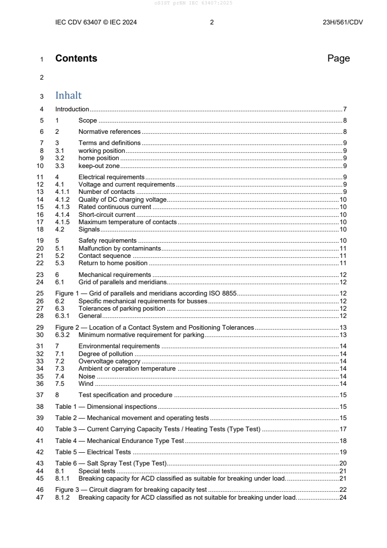
1 Contents Page
3 Inhalt
4 Introduction . 7
5 1 Scope . 8
6 2 Normative references . 8
7 3 Terms and definitions . 9
8 3.1 working position . 9
9 3.2 home position . 9
10 3.3 keep-out zone . 9
11 4 Electrical requirements . 9
12 4.1 Voltage and current requirements . 9
13 4.1.1 Number of contacts . 9
14 4.1.2 Quality of DC charging voltage. 10
15 4.1.3 Rated continuous current . 10
16 4.1.4 Short-circuit current . 10
17 4.1.5 Maximum temperature of contacts . 10
18 4.2 Signals . 10
19 5 Safety requirements . 10
20 5.1 Malfunction by contaminants . 11
21 5.2 Contact sequence . 11
22 5.3 Return to home position . 11
23 6 Mechanical requirements . 12
24 6.1 Grid of parallels and meridians. 12
25 Figure 1 — Grid of parallels and meridians according ISO 8855 . 12
26 6.2 Specific mechanical requirements for busses . 12
27 6.3 Tolerances of parking position . 12
28 6.3.1 General . 12
29 Figure 2 — Location of a Contact System and Positioning Tolerances . 13
30 6.3.2 Minimum normative requirement for parking . 13
31 7 Environmental requirements . 14
32 7.1 Degree of pollution . 14
33 7.2 Overvoltage category . 14
34 7.3 Ambient or operation temperature . 14
35 7.4 Noise . 14
36 7.5 Wind . 14
37 8 Test specification and procedure . 15
38 Table 1 — Dimensional inspections . 15
39 Table 2 — Mechanical movement and operating tests . 15
40 Table 3 — Current Carrying Capacity Tests / Heating Tests (Type Test) . 17
41 Table 4 — Mechanical Endurance Type Test . 18
42 Table 5 — Electrical Tests . 19
43 Table 6 — Salt Spray Test (Type Test) . 20
44 8.1 Special tests . 21
45 8.1.1 Breaking capacity for ACD classified as suitable for breaking under load. . 21
46 Figure 3 — Circuit diagram for breaking capacity test . 22
47 8.1.2 Breaking capacity for ACD classified as not suitable for breaking under load. . 24
oSIST prEN IEC 63407:2025
IEC CDV 63407 © IEC 2024 3 23H/561/CDV
48 9 Documentation . 24
49 Annex A (normative) ACD mounted on the infrastructure - ACD counterpart on the roof of the vehicle
50 . 25
51 A.1 Generals of infrastructure mounted ACD function . 25
52 A.2 ACD mounted on the infrastructure – ACD counterpart on the roof of the vehicle with two in-
53 line and two parallel contact bars . 25
54 A.2.1 ACD counterpart mechanical arrangement . 25
55 Figure A.1 — Mechanical arrangement of counter part . 27
56 Figure A.2 — Principal proposal roof rail shapes with rounded surfaces . 27
57 A.2.2 Keep-out zone . 28
58 Figure A.4 — Keep-out zone driving direction . 29
59 Figure A.5 — Keep-out zone vertical to driving direction . 30
60 A.2.3 Mechanical arrangement moving part . 30
61 A.2.4 Connected moving part and counterpart (informative) . 31
62 Figure A.6 — Connected mobile assembly automatic coupler . 32
63 A.2.5 Specific requirements . 32
64 A.2.5.1 Contact force . 32
65 A.2.5.2 Specific gauge for testing . 32
66 A.2.5.3 Gauge as standard ACD counterpart for testing an ACD . 32
67 Figure A.7 — Gauge ACD counterpart . 33
68 A.2.5.4 Gauge as standard ACD for testing an ACD counterpart . 33
69 Figure A.8 — Gauge ACD . 34
70 A.3 ACD mounted on the infrastructure – ACD counterpart on the roof of the vehicle with in-line
71 roof contact bars . 34
72 A.3.1 Additional generals for this application . 34
73 A.3.2 ACD counterpart mechanical arrangement . 34
74 Figure A.9 — Mechanical arrangement of counter part . 36
75 Figure A.10 — Roof rail shapes with rounded surfaces CP and PE . 37
76 Figure A.11 — Roof rail shapes with rounded surfaces DC+ and DC- . 38
77 A.3.3 Keep-out zone . 38
78 Figure A.12 — Keep-out zone . 39
79 Figure A.13 — Example of keep-out zone driving direction for a truck . 40
80 A.3.4 Mechanical arrangement moving part . 40
81 A.3.5 Connected moving part and counterpart (informative) . 41
82 Figure A.14 — Illustration of the automatic coupler when connected . 42
83 A.3.6 Specific requirements . 43
84 A.3.6.1 Contact force . 43
85 A.3.6.2 Test specification and procedure . 43
86 A.3.6.3 Specific gauge for testing . 43
87 A.3.6.4 Gauge as standard ACD counterpart for testing an ACD . 43
88 Figure A.15 — Gauge ACD counterpart . 44
89 A.3.6.5 Gauge as standard ACD for testing an ACD counterpart . 44
oSIST prEN IEC 63407:2025
IEC CDV 63407 © IEC 2024 4 23H/561/CDV
90 Figure A.16 — Gauge ACD . 44
91 A.4 ACD mounted on the infrastructure – ACD counterpart on the roof of the vehicle with contact
92 dome . 45
93 A.4.1 Additional generals for this application . 45
94 A.4.2 ACD counterpart mechanical arrangement . 45
95 Figure A.17 — mechanical arrangement of counter part . 46
96 Figure A.18 — Mechanical arrangement of counter part . 47
97 A.4.3 ACD counterpart keep-out zone . 48
98 A.4.3.1 General . 48
99 Figure A.19 — Keep-out zone driving direction and vertical to driving direction . 48
100 A.4.3.2 Mechanical arrangement moving part . 48
101 A.4.4 Specific requirements . 48
102 A.4.4.1 Contact force . 48
103 A.4.4.2 Specific gauge for testing . 49
104 A.4.4.3 Gauge as standard ACD counterpart for testing an ACD . 49
105 Figure A.20 — Gauge ACD counterpart . 49
106 A.4.4.4 Gauge as standard ACD for testing an ACD counterpart . 49
107 Figure A.21 — Gauge ACD . 50
108 Annex B (normative) ACD mounted on the roof of the vehicle - ACD counterpart on the infrastructure
109 . 51
110 B.1 General . 51
111 B.2 Mechanical arrangement ACD counterpart . 51
112 Figure B.1 — ACD Counterpart in infrastructure, principle positions of contact strips, dimension of
113 connection interface . 53
114 B.3 ACD counterpart keep-out zone . 53
115 Figure B.2 — Side view of ACD counterpart, ACD working range and keep-out zone . 53
116 Figure B.3— Front view of ACD counterpart, ACD working range and keep-out zone . 54
117 B.4 Mechanical arrangement moving part . 54
118 B.5 Specific requirements . 55
119 B.5.1 Contact forces . 55
120 B.5.2 Specific gauge for testing . 55
121 B.5.2.1 General . 55
122 B.5.2.2 Gauge as standard ACD counterpart for testing an ACD . 55
123 Figure B.4 — Gauge ACD counterpart . 56
124 B.5.2.3 Gauge as standard ACD for testing an ACD counterpart . 56
125 Figure B.5 — Gauge ACD . 57
126 Annex C (normative) ACD mounted underneath the vehicle - ACD counterpart on the ground . 58
127 C.1 General . 58
128 C.2 ACD mounted underneath the vehicle - ACD counterpart on the infrastructure with three in-line
129 contact segments . 58
130 C.2.1 ACD counterpart mechanical arrangement . 58
131 Figure C.1 — Mechanical arrangement of ACD counter part . 60
oSIST prEN IEC 63407:2025
IEC CDV 63407 © IEC 2024 5 23H/561/CDV
132 C.2.2 ACD mechanical arrangement . 61
133 Figure C.2 — Mechanical arrangement of ACD . 62
134 C.3 Connected automatic coupler. 62
135 Figure C.3 — Automatic coupler (nominal position) . 63
136 Figure C.4 — Automatic coupler (extreme left and front position) . 64
137 C.4 Keep-out-zone . 64
138 C.5 Specific requirements . 65
139 C.5.1 Lateral positioning . 65
140 C.5.2 Longitudinal positioning . 65
141 C.5.3 Vertical positioning . 65
142 C.5.4 Reachable contacts . 65
143 C.5.5 Contact force . 65
144 C.5.6 Rated current (short-term current). 65
145 C.5.7 Curb lateral reference . 65
146 Figure C.5 — Curb shape boss type . 66
147 Figure C.6 — Curb shape recess type . 66
148 Figure C.7 — ACD counterpart roadway integration (top view) for information only . 66
149 C.5.8 Protection by obstacle . 67
150 C.5.9 Protection by obstacle – Vehicle requirement . 67
151 Figure C.8 — Maximum vehicle height and barrier close to the vehicle . 67
152 Figure C.9 — Maximum vehicle height with lowest and safe position detection of the barrier . 67
153 Figure C.10 — Minimum vehicle height . 67
154 C.5.10 Power interface . 67
155 C.5.11 Control/command interface . 68
156 C.5.11.1.1 Earthing . 68
157 C.5.11.1.2 Detection . 68
158 Figure C.11 — Signal loop layout. 68
159 C.6 Specific tests specification and procedure . 68
160 Table C.1 — Additional Mechanical Tests . 69
161 Table C.2 — Additional Electrical Tests . 69
162 C.7 Specific gauge for testing . 69
163 C.7.1 General . 69
164 C.7.2 Gauge as standard ACD counterpart for testing an ACD . 69
165 Figure C.12 — Mechanical arrangement of ACD counterpart 3D view . 70
166 Figure C.13 — Mechanical arrangement of ACD counter part . 70
167 C.7.3 Gauge as standard ACD for testing an ACD counterpart . 70
168 Annex D (normative) ACD mounted on the infrastructure and connecting to the side or on the roof of
169 the vehicle and ACD mounted on the side or on the roof of the vehicle and connecting to the
170 infrastructure. 72
171 D.1 General . 72
172 Table D.1 — ACD Type D Sizes . 72
173 Figure D.1 — Overview of case D and case E mounting vehicle and stationary side . 73
oSIST prEN IEC 63407:2025
IEC CDV 63407 © IEC 2024 6 23H/561/CDV
174 D.2 Safety . 73
175 D.2.1 General . 73
176 D.2.2 Degree of protection against hazardous-live-parts . 73
177 D.2.3 Contact sequencing . 73
178 D.2.4 Prevention of damages from unintended movement . 73
179 D.3 Mechanical arrangement of the counterpart . 74
180 D.3.1 General . 74
181 D.3.2 Moving pin side . 74
182 Figure D.2 — ACD plug side (moving) . 74
183 D.3.3 Dimensional requirements . 74
184 Figure D.3 — Dimensions of contact arrangement on pin side . 75
185 D.3.4 Contact quality and plating . 75
186 D.4 Test specification and procedure . 76
187 D.5 Mechanical arrangement of the socket side . 76
188 Figure D.4 — ACD socket side . 76
189 Figure D.5 — Example of ACD socket side cone dimension . 77
190 D.6 Keep-out zone . 77
191 Figure D.6 — Example of Keep-out zone CD socket side dimensions . 78
192 Bibliography . 79
oSIST prEN IEC 63407:2025
IEC CDV 63407 © IEC 2024 7 23H/561/CDV
195 Introduction
196 The electrical interface for charging electrically propelled vehicles with plugs, socket-outlets, vehicle
197 connectors and vehicle inlets is described in IEC 62196 series and IEC 61851-23. For heavier vehicles such
198 as buses and trucks, requirements of short charging times with high energy present a problem of handling,
199 and safety with hand-held connecting devices. For these high current charging applications, an automated
200 connection device (ACD) is of interest.
201 An automatic coupler consists out of a mobile assembly with electrical contacts, called ACD and fixed
202 electrical contacts, called ACD counterpart. Automatic couplers allow an unmanned connection of high-
203 current contacts and signal/control contacts.
204 This document contains requirements for all type of ACDs. Its annexes describe specific implementations
205 and specific requirements. This document is expected to be read in conjunction with IEC 61851-23-1:— .
Under preparation. Stage at time of publication: IEC CDV 61851-23-1:2020.
oSIST prEN IEC 63407:2025
IEC CDV 63407 © IEC 2024 8 23H/561/CDV
206 1 Scope
207 This document is applicable to automatic couplers of standardized configuration, intended for use in electric
208 vehicle conductive charging systems which incorporate control means, with rated operating voltage up to 1
209 500 V DC.
210 This document applies to high power DC interfaces intended for use in isolated conductive charging systems,
211 for circuits specified in IEC 61851-23-1:— .
212 The requirements of this standard applies only to automatic couplers defined in the annexes A, B, C and D
213 of this document.
214 The ACDs covered by this document are used only in charging mode 4, according to IEC 61851-23-1:— ,
215 3.1.201 Case D or 3.1.202 Case E.
216 This document describes the requirements for an automatic couplers in regard of safety, function and testing.
217 This document describes basic parameters that can be standardized for different automatic couplers s.
218 Automatic couplers s following these standardized parameters will have the benefit of being compatible,
219 even if they are based on different technologies.
220 This document does not apply to solutions based on a vehicle connector described in IEC 62196-3 and IEC
221 TS63379 driven by an automatic mechanism, as, for instance, a robotic arm.
222 This document does not apply to systems described in IEC 61851-26.
223 This document does not cover all safety aspects related to maintenance.
224 2 Normative references
225 The following documents are referred to in the text in such a way that some or all of their content constitutes
226 requirements of this document. For dated references, only the edition cited applies. For undated references,
227 the latest edition of the referenced document (including any amendments) applies.
228 EN 1652, Copper and copper alloys - Plate, sheet, strip and circles for general purposes
229 EN 12163, Copper and copper alloys - Rod for general purposes
230 EN 12167, Copper and copper alloys - Profiles and bars for general purposes
231 IEC 60068-2-11, Environmental testing - Part 2: Tests - Test Ka: Salt mist
232 IEC 60204-1: 2016, Safety of machinery – Electrical equipment of machines – Part 1: General requirements
233 IEC 60309-1, Plugs, fixed or portable socket-outlets and appliance inlets for industrial purposes – Part 1:
234 General requirements
235 IEC 60512-2-2, Connectors for electronic equipment - Tests and measurements – Part 2-2: Electrical
236 continuity and contact resistance tests - Test 2b: Contact resistance – Specified test current method
237 IEC 60512-5-1, Connectors for electronic equipment - Tests and measurements - Part 5-1: Current-carrying
238 capacity tests - Test 5a: Temperature rise (IEC 60512-5-1)
239 IEC 60512-5-2, Connectors for electronic equipment - Tests and measurements - Part 5-2: Current-carrying
240 capacity tests - Test 5b: Current-temperature derating (IEC 60512-5-2)
241 IEC 60529, Degrees of protection provided by enclosures (IP Code)
242 IEC 61851-1:2019, Electric vehicle conductive charging system - Part 1: General requirements
243 IEC 61984:2008, Connectors - Safety requirements and tests
oSIST prEN IEC 63407:2025
IEC CDV 63407 © IEC 2024 9 23H/561/CDV
244 IEC 61851-23-1:—, Electric vehicle conductive charging system – Part 23-1: DC charging with an automatic
245 connection system
246 IEC 62196-1:2014, Plugs, socket-outlets, vehicle connectors and vehicle inlets - Conductive charging of
247 electric vehicles - Part 1: General requirements
248 IEC 62497-1, Railway applications – Insulation coordination – Part 1: Basic requirements – Clearances and
249 creepage distances for all electrical and electronic equipment
250 ISO/DIS 5474-3, Electrically propelled road vehicles - Functional requirements and safety requirements for
251 power transfer - Part 3: DC power transfer
252 IEC 62477-1:2016, Safety requirements for power electronic converter systems and equipment – Part 1:
253 General
254 IEC TS 63379, Plugs, socket-outlets, vehicle connectors and vehicle inlets – conductive charging of electric
255 vehicles - Vehicle connector, vehicle inlet and cable assembly for Megawatt DC charging—
256 3 Terms and definitions
257 For the purposes of this document, the terms and definitions given in IEC 61851-23-1:— and the following
258 apply.
259 ISO and IEC maintain terminological databases for use in standardization at the following addresses:
260 — ISO Online browsing platform: available at https://www.iso.org/obp
261 — IEC Electropedia: available at http://www.electropedia.org/
262 3.1 working position
263 position reached when the ACD and the fixed ACD counterpart have mated and when the physical contact
264 is established, and energy transfer is allowed
265 3.2 home position
266 position where the ACD is not engaged with its counterpart and where safe clearance is present with street
267 and infrastructure
268 3.3 keep-out zone
269 Space around automatic coupler, where no items shall be installed to avoid collision with any moving part of
270 the ACD or ACD counterpart.
271 4 Electrical requirements
272 4.1 Voltage and current requirements
273 4.1.1 Number of contacts
274 For systems described in IEC 61851-23-1:— , Annexes AA, BB and CC:
1 1
275 Four contacts: DC+, DC-, PE and CP (IEC 61851-23-1:— , Figure AA.1, IEC 61851-23-1:— , Figure BB.1
276 and IEC 61851-23-1:— , Figure CC.14)
277 For systems described in IEC 61851-23-1:— , Annex KK:
278 three contacts: DC+, DC-, PE (IEC 61851-23-1:— , Figure KK.14)
Under preparation. Stage at time of publication: IEC CDV 61851-23-1:2020.
Under preparation.
oSIST prEN IEC 63407:2025
IEC CDV 63407 © IEC 2024 10 23H/561/CDV
279 4.1.2 Quality of DC charging voltage
280 Since the ACD is part of the power transmitting system, its influence on the quality of DC charging voltage
281 shall be considered, to not exceed the levels indicated in IEC 61851-23-1: Chapter 101.1.2 — .
282 4.1.3 Rated continuous current
283 The rated current can be a continuous current or the average of an intermittent current.
284 The rated current is defined by the vehicle and the application. The manufacturer of the ACD shall guarantee
285 that his system is sized and safe for this current by confirming the physical values described in this document.
286 In the case of an automatic coupler consisting of an ACD and an ACD counterpart from different or unknown
287 manufacturers, the minimum current requirements that fulfil the requirements for a particular annex of this
288 document shall be assumed unless there are sensing devices that can reliably determine if the ACD is
289 operating within the defined limits of this document. However, if the ACD and the ACD counterpart can be
290 definitively determined to be of a particular type and manufacturer, higher currents with or without sensing
291 devices can be used, according to manufacturer’s specifications.
292 4.1.4 Short-circuit current
293 In case of short circuit, the ACD shall not cause dangerous situation such as an explosion or a fire. After
294 such a short circuit, the ACD shall be checked for proper function prior further service. The procedure for
295 checking proper function shall be part of the maintenance manual.
297 For the values of short circuit current please reference to IEC 61851-23-1 chapter 13.101 (69/943/NP).
298 For the actual values of short circuit current please refer to IEC61851-23-1 chapter 13.101.
299 4.1.5 Maximum temperature of contacts
300 The contacts of the automatic coupler have a temperature rise depending on the charging current
301 (rated continuous current or intermitted current). This temperature rise shall be considered by the
302 system integrator, so that it has no damaging influence on materials or devices in the surrounding
303 of the automatic coupler at vehicle side and infrastructure side.
304 The ACD manufacturer shall indicate this maximum temperature rise for a rated current and the ambient
305 temperature at which it is reached in their documentation.
306 1 IEC 61851-23-1 under development, all references are to IEC 69/943/NP version.
308 Compliance is checked by test in Clause 8, Table 3.
309 4.2 Signals
310 The minimum signals required are the status (the position) of the ACD. All other signalling necessary for
311 pairing or charging are described in IEC 61851-23-1:— or in ISO 15118.
312 Signal 1: ACD is in home position.
313 Signal 2: ACD has reached working position (see annexes for specific implementation).
314 The home position signal is a “safety-related part of a control system (SRP/CS)” in regard of ISO 13849-1; chapter 3.1.1.
315 NOTE: There may be a timeout if ACD is moved but the working position has not been reached in a specific time frame.
316 This time frame has to be defined by the ACD manufacturer. This time out functionally is described in IEC 61851-23-1:—.
317 5 Safety requirements
318 Relevant safety requirements in regard of the system are given by the IEC 61851-23-1.
oSIST prEN IEC 63407:2025
IEC CDV 63407 © IEC 2024 11 23H/561/CDV
319 5.1 Malfunction by contaminants
320 In case of blocking contaminants, the ACD might not reach the home position. There shall be an installed
321 system that monitors the ACD to reach the home position (see 4.2). This shall be realized by the ACD itself
322 and communicated to the overall system (EV or EVSE).
323 NOTE: For reaction of this missing home position signal, refer to IEC 61851-23-1:— , CC.5.201, KK.5.201 or
324 ISO 5474-:7.6.5.
325 5.2 Contact sequence
326 According to IEC 61851-23-1:— , the connection and disconnection of the ACD shall be done without
327 current under normal operation. It is not necessary to have a contact sequence. But if a contact sequence is
328 applied, the order of disconnection shall be one of:
330 – CP contact,
331 – DC power contacts,
332 – PE contact.
334 Or
336 – PE contact,
337 – DC power contacts,
338 – CP contact.
340 Or
342 – CP and PE contacts,
343 – DC power contacts.
345 The ACD shall be classified by the manufacturer as either suitable or not suitable to break under load
346 depending on whether or not breaking under load is possible under normal operation.
347 Compliance is checked by test in clause 8.1 breaking capacity.
348 NOTE: Under fault emergency disconnection situation during power transfer without a first disconnecting CP or PE,
349 arcing cannot be avoided. It is recommended to have a first disconnecting CP/PE or a guaranteed arc resistive system,
350 so that no danger situation due to that arc can occur (i. e. fire). Scope is safety and not contact degradation.
351 5.3 Return to home position
352 In case of an intentional or unintentional loss of supply power for the actuator of the ACD, the ACD shall
353 return to its home position. For details refer to IEC 61851-23-1:— , Clause 201.3 “Loss of power”
354 Compliance is checked by test in Clause 8, Table 1 Test Number B3.
oSIST prEN IEC 63407:2025
IEC CDV 63407 © IEC 2024 12 23H/561/CDV
355 6 Mechanical requirements
356 6.1 Grid of parallels and meridians
358 Key
No Part
1 Reference point – axle A as explained in 6.2
2 Ground level
359 Figure 1 — Grid of parallels and meridians according ISO 8855
360 6.2 Specific mechanical requirements for busses
361 Distinction shall be made with regards to the several vehicle dimensions, for instance double/single deck
362 buses, resulting in several distances between the ACD and the ACD counterpart.
363 The centre of the nominal working position of the automatic coupler is over the axle A of the electrical vehicle
364 and the centre line from front to back.
365 The system integrator shall ensure the correct position of the ACD or ACD counterpart on the electric vehicle
366 and infrastructure.
367 NOTE: The position of the ACD or ACD counterpart on the EV depends on e.g. the installation height on the EV, the
368 installation height in the infrastructure, the curve of horizontal displacement over the working height of the ACD system
369 and vehicle height. Care should be taken to interoperability of different EVs and infrastructure situations.
370 Axle A is defined as the first front axle in regard of the driving direction of the vehicle.
371 This is the reference point for the parking tolerances during charging: x-centre, y-centre, z-centre of axle A
372 6.3 Tolerances of parking position
373 6.3.1 General
374 Figure 2 shows the location of contact systems and positioning tolerances.
oSIST prEN IEC 63407:2025
IEC CDV 63407 © IEC 2024 13 23H/561/CDV
376 Key
No Part
1 Axle A
2 ΦZ
3 ΦX
4 ΦSlope
377 Figure 2 — Location of a Contact System and Positioning Tolerances
378 6.3.2 Minimum normative requirement for parking
379 The minimal positioning tolerances that have to be compensated while positioning the vehicle for charging,
380 are in X- and Y- directions and, for positioning angle, between vehicle and curb:
381 X at least ± 200 mm (∆x)
382 Y at least ± 200 mm (∆y), Y at least 0 to + 200 mm for Annex C
383 Angle between vehicle and curb (Φx) up to ± 2°.
384 Being connected and the vehicle being immobilized, the ACD shall also deal with tolerances of the vehicle
385 caused by dynamic movements, i. e. due to kneeling, wind, passenger on and off, etc., and has to avoid
386 losing contact.
388 NOTE: Typically, an immobilized vehicle should mean, that the drivetrain is disabled and parking brake is applied.
389 If any of above required tolerances are exceeded in service, no dangerous or damaging situation shall occur.
390 This can be done by physical limits, as for instance, curbs or sensors detecting the right position, by
391 automatic coupler design or by operational constraints, such as prohibiting kneeling when conn
...