

oSIST IEC 60884-1:2026
(Main)Plugs and socket-outlets for household and similar purposes - Part 1: General requirements
- Abstract
CORRECTED VERSION 2026-07
IEC 60884-1:2022 applies to plugs and fixed or portable socket-outlets for AC only, with or without earthing contact, with a rated voltage greater than 50 V but not exceeding 440 V and a rated current not exceeding 32 A, intended for household and similar purposes, either indoors or outdoors.
Compatible plugs and socket-outlets, when combined, form a plug and socket-outlet system. Standardized systems used around the world are reported in IEC/TR 60083.
The rated current is limited to 16 A maximum for accessories provided with screwless-type terminals.
This fourth edition cancels and replaces the third edition published in 2002, Amendment 1:2006 and Amendment 2:2013. This edition constitutes a technical revision.
This edition includes the following significant technical changes with respect to the previous edition:
plugs and socket-outlets incorporating pilot lights;
crimped connections in accessories;
insulation piercing terminals (IPT);
accessories to be used with American Wire Gauge (AWG) cables;
accessories used in T° below −5 °C down to and including −45 °C;
accessories used in T° above +40 °C up to and including +70 °C;
plugs and socket-outlets for high load (HL);
clarification of some definitions;
durability of markings test;
introduction of thermal monitoring in the plug;
requirements for shutters in portable socket-outlets;
test walls for the verification of ingress of water;
rewriting of the temperature rise clause.
The contents of the corrigendum of November 2023 have been included in this copy.
- Status
- Not Published
- Public Enquiry End Date
- 29-Sep-2026
- Technical Committee
- EPR - Electrical accessories
- Current Stage
- 6060 - National Implementation/Publication (Adopted Project)
- Start Date
- 08-Oct-2026
- Due Date
- 13-Dec-2026
Buy Documents
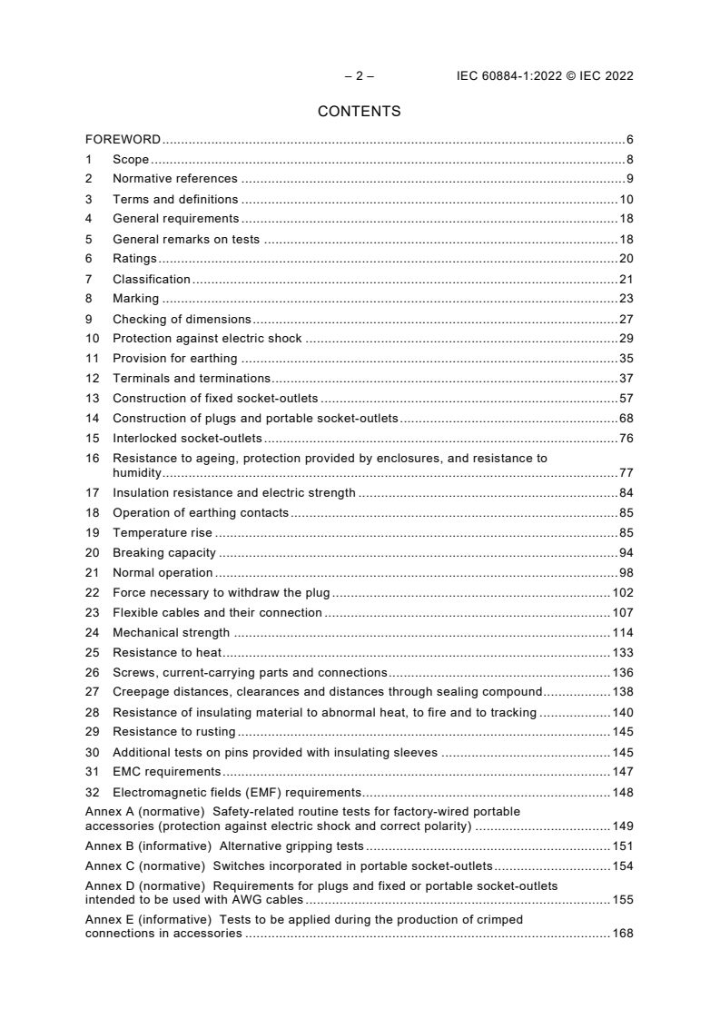
IEC 60884-1:2022 - Plugs and socket-outlets for household and similar purposes - Part 1: General requirements
IEC 60884-1:2022 - Plugs and socket-outlets for household and similar purposes - Part 1: General requirements

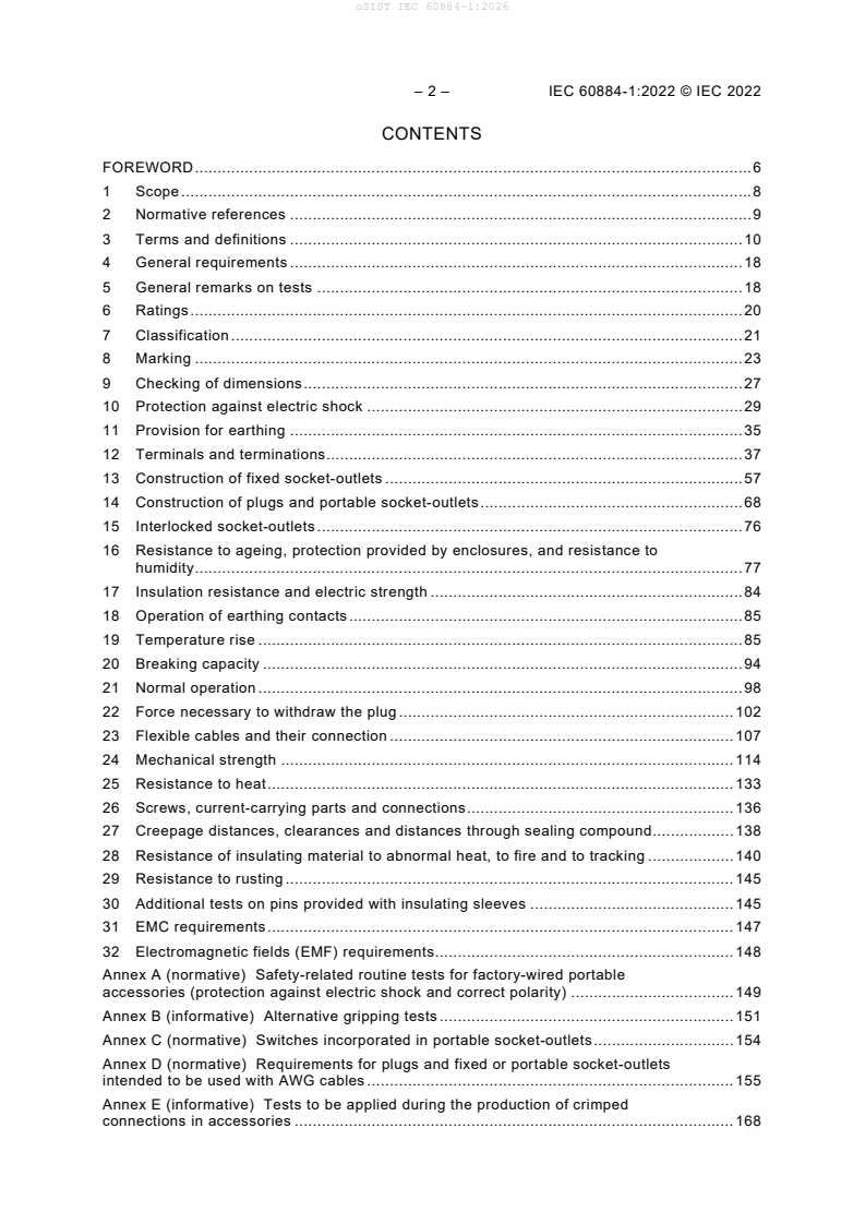
oSIST IEC 60884-1:2026 is a Slovene standard published by SIST and identical to IEC 60884-1:2022, corrected version 2026-07. It specifies the general requirements and test methods for plugs and fixed or portable socket-outlets for alternating current (AC) household and similar use, so designers, test labs, quality teams and buyers can check which accessories, ratings and constructions are covered.
What does oSIST IEC 60884-1:2026 specify?
oSIST IEC 60884-1:2026 covers plugs and fixed or portable socket-outlets for AC only, with or without earthing contact, for rated voltages greater than 50 V and up to 440 V, and rated currents up to 32 A. It also covers plugs that are part of cord sets, plugs and portable socket-outlets that are part of cord extension sets, plugs and socket-outlets built into appliances unless the appliance standard says otherwise, and plugs and socket-outlets with pilot lights.
The standard is organized into 32 clauses plus Annexes A to I. The body runs from scope, references and terms through ratings, classification, marking, dimensions, safety, terminals, construction, performance tests, mechanical tests, fire and tracking tests, rusting, electromagnetic compatibility (EMC) and electromagnetic fields (EMF).
| Annex | What it covers |
|---|---|
| A | Safety-related routine tests for factory-wired portable accessories |
| B | Alternative gripping tests |
| C | Switches incorporated in portable socket-outlets |
| D | Requirements for plugs and fixed or portable socket-outlets intended to be used with AWG cables |
| E | Tests to be applied during production of crimped connections in accessories |
| F | Additional requirements for accessories provided with insulation-piercing terminals |
| G | Additional tests and requirements for accessories intended for ambient temperatures below -5 °C down to and including -45 °C |
| H | Additional tests and requirements for accessories intended for ambient temperatures above +40 °C up to and including +70 °C |
| I | Additional requirements and tests for plugs and socket-outlets for high load (HL) application |
The scope limits screwless-type terminals to a maximum rated current of 16 A. It also says the document only covers mounting boxes to the extent needed for socket-outlet tests, and it points readers to IEC 60670-1 for general-purpose mounting boxes.
The document excludes industrial plugs, socket-outlets and couplers, appliance couplers, plugs and socket-outlets for extra low voltage (ELV), and fixed socket-outlets combined with fuses, automatic switches or similar devices. It also notes that plugs are intended to be energized by socket-outlets, and that special locations such as ships, vehicles and hazardous areas may need extra requirements.
What are the key requirements of oSIST IEC 60884-1:2026?
oSIST IEC 60884-1:2026 is built around the idea that an accessory is acceptable only if it performs reliably in normal use and its risks are reduced to a tolerable level. Compliance is shown by meeting all relevant clauses and tests, not by a single pass or one isolated check.
Ratings and product classification
Clause 6 sets the rating framework, including the voltage and current ranges, and points to preferred combinations of type and rating. In practice, manufacturers need to choose a configuration that matches the intended installation and conductor sizes, rather than treating plugs and socket-outlets as generic parts.
Clause 7 classifies accessories by earthing provision, rewirability, terminal type, conductor type, protection against electric shock, shutters, mounting style, installation method and intended use. This matters because the construction, marking and tests depend on the class you choose.
Marking, dimensions and protection against electric shock
Clause 8 requires clear and durable marking, including symbols and specific markings for fixed and portable accessories. For a buyer or inspector, the point is that the product must identify its rating and intended use in a way that remains readable after normal handling.
Clause 9 checks dimensions and compatibility. Clause 10 deals with protection against electric shock, including access to live parts, single-pole insertion, shutters and increased protection. Clause 11 covers earthing so that earthing contacts are effective, accessible metal parts are addressed, and earthing contacts make first and break last.
Terminals, construction and special variants
Clause 12 sets the rules for terminals and terminations, including screw-type terminals, screwless-type terminals, insulation-piercing terminals (IPT) and crimped connections. The practical meaning is that the terminal must accept the specified conductor types and sizes, hold them securely, and survive mechanical and thermal stress without loosening.
Clauses 13 to 15 cover the construction of fixed socket-outlets, plugs and portable socket-outlets, and interlocked socket-outlets. These clauses are where the standard turns safety ideas into design details such as covers, cover-plates, mounting, strain relief, shutters, cord anchorage, and the rule that an interlocked socket-outlet must not allow unsafe insertion or withdrawal while live.
Type tests, routine tests and performance checks
Clauses 16 to 18 cover ageing, humidity, insulation resistance, electric strength and the operation of earthing contacts. Clauses 19 to 21 cover temperature rise, breaking capacity and normal operation. In practice, these are the core proving tests for a finished design, showing that it can carry current, interrupt current and survive repeated use.
Clause 22 checks the force needed to withdraw the plug and, where relevant, the force to operate shutters during insertion. Clause 23 checks flexible cables, cord anchorage and cable entry. Clauses 24 and 25 cover mechanical strength and resistance to heat, while Clauses 26 and 27 cover screws, current-carrying parts, connections, creepage distances, clearances and insulating sealing compound.
Clauses 28 to 30 deal with resistance to abnormal heat, fire and tracking, resistance to rusting, and additional tests on pins with insulating sleeves. Clauses 31 and 32 cover EMC requirements and EMF requirements. For users, these clauses show that the product must remain safe after mechanical abuse, thermal stress, moisture exposure and repeated handling.
Special applications in the annexes
The annexes extend the main body to special cases such as AWG cables, crimped connections, IPT, low-temperature use, high-temperature use and HL application. Annex I is especially important where long, repetitive high-current cycling is expected, because it adds extra requirements and tests beyond the normal household-duty case.
What terms does oSIST IEC 60884-1:2026 define?
- plug - An accessory with pins designed to engage with the contacts of a socket-outlet, allowing manual connection and disconnection of a load.
- socket-outlet - An accessory with socket-contacts designed to engage with the pins of a plug.
- portable socket-outlet - A socket-outlet connected to, or integral with, one flexible cable and intended to be easily moved while connected to the supply.
- screwless-type terminal - A connecting device that makes and releases conductor connections by spring or similar means, without special conductor preparation other than stripping insulation.
- insulation-piercing terminal (IPT) - A terminal that connects conductors by piercing, boring through, cutting through or otherwise making ineffective the insulation without prior stripping.
- high load (HL) - A load that applies long and repetitive cycles up to the rated current, beyond normal load conditions.
- routine test - A test applied to each individual device during and/or after manufacture to check compliance with specified criteria.
Who uses oSIST IEC 60884-1:2026?
Manufacturers of plugs, socket-outlets, extension sets, cord sets and related electrical accessories use oSIST IEC 60884-1:2026 to design products, choose terminals, select materials and plan validation tests. Test laboratories and certification bodies use it to carry out type tests and routine tests on safety, endurance, heat, moisture, IP-related performance and mechanical strength.
Quality managers use it to define acceptance checks for incoming parts and finished goods, especially for terminals, markings, cord anchorage, shutters and earthing performance. Buyers, specifiers and product engineers use it to compare household and similar-purpose accessories by rating, construction type and intended installation.
What changed in oSIST IEC 60884-1:2026 from the previous edition?
oSIST IEC 60884-1:2026 cancels and replaces the third edition published in 2002, Amendment 1:2006 and Amendment 2:2013. It is identified as a technical revision.
The significant technical changes listed for this edition are:
- plugs and socket-outlets incorporating pilot lights
- crimped connections in accessories
- insulation-piercing terminals (IPT)
- accessories to be used with American Wire Gauge (AWG) cables
- accessories used at temperatures below -5 °C down to and including -45 °C
- accessories used at temperatures above +40 °C up to and including +70 °C
- plugs and socket-outlets for high load (HL)
- clarification of some definitions
- durability of markings test
- thermal monitoring in the plug
- requirements for shutters in portable socket-outlets
- test walls for verification of ingress of water
- rewritten temperature rise clause
The copy also includes the contents of the November 2023 corrigendum.
Which standards are used with oSIST IEC 60884-1:2026?
| Standard | What it contributes |
|---|---|
| IEC/TR 60083 | Reports standardized plug and socket-outlet systems used around the world |
| IEC 60068-2-30 | Damp heat, cyclic test method |
| IEC 60068-2-31 | Rough handling shocks |
| IEC 60068-2-75 | Hammer tests |
| IEC 60112 | Proof and comparative tracking indices of solid insulating materials |
| IEC 60227 (all parts) | PVC insulated cables up to and including 450/750 V |
| IEC 60245 (all parts) | Rubber insulated cables up to and including 450/750 V |
| IEC 60529 | Degrees of protection provided by enclosures, the IP Code |
| IEC 60669 (all parts) | Switches for household and similar fixed-electrical installations |
| IEC 60669-2-1:2021 | Electronic control devices for household and similar fixed electrical installations |
| IEC 60695-2-10:2021 | Glow-wire apparatus and common test procedure |
| IEC 60695-2-11:2021 | Glow-wire flammability test method for end products |
| IEC 60884-2-1 | Particular requirements for fused plugs |
| IEC 61032:1997 | Probes for verification of protection by enclosures |
| IEC 61058 (all parts) | Switches for appliances |
| IEC 61545 | Devices for the connection of aluminium conductors in clamping units |
| ISO/IEC Guide 51 | Safety aspects - Guidelines for their inclusion in standards |
| ISO 1456:2009 | Nickel and related electrodeposited coatings |
| ISO 2081:2018 | Zinc electroplated coatings on iron or steel |
| ISO 2093:1986 | Tin electroplated coatings |
The document also names IEC 60670-1 for general-purpose mounting boxes, IEC 60884-2-5 for adaptors, and IEC 60884-2-6 for interlocked socket-outlets.
What does the oSIST IEC 60884-1:2026 document contain?
The document contains tables for preferred ratings, conductor cross-sections, torques, pull forces, test currents, withdrawal forces, cable dimensions and creepage distances. It also contains figures for example accessories, terminals, gauges, test pistons, impact devices, cord retention, shutter verification, test walls, temperature-rise set-ups and HL test arrangements.
Many clauses are written as test methods, so the document is used directly for type testing, design verification and compliance evaluation. Annex A supports routine production tests for factory-wired portable accessories, while Annex E supports production checks for crimped connections.
Several annexes add use-case-specific requirements instead of repeating the main body. That structure lets a reader work from the general household AC accessory rules first, then move to AWG, IPT, crimped, temperature-extreme or HL cases only when those product variants are needed.
Relations
- Effective Date
- 31-Jul-2026
- Effective Date
- 19-Jun-2026
- Effective Date
- 05-Sep-2023
Buy Documents
IEC 60884-1:2022 - Plugs and socket-outlets for household and similar purposes - Part 1: General requirements
IEC 60884-1:2022 - Plugs and socket-outlets for household and similar purposes - Part 1: General requirements
Get Certified
Connect with accredited certification bodies for this standard

IMQ S.p.A. (Certification)
Italian electrical product certification.

SLG Prüf- und Zertifizierungs GmbH
German testing and certification body.

UL Solutions
Global safety science company with testing, inspection and certification.
Sponsored listings
Frequently Asked Questions
oSIST IEC 60884-1:2026 is a standard published by the Slovenian Institute for Standardization (SIST). Its full title is "Plugs and socket-outlets for household and similar purposes - Part 1: General requirements". This standard covers: CORRECTED VERSION 2026-07 IEC 60884-1:2022 applies to plugs and fixed or portable socket-outlets for AC only, with or without earthing contact, with a rated voltage greater than 50 V but not exceeding 440 V and a rated current not exceeding 32 A, intended for household and similar purposes, either indoors or outdoors. Compatible plugs and socket-outlets, when combined, form a plug and socket-outlet system. Standardized systems used around the world are reported in IEC/TR 60083. The rated current is limited to 16 A maximum for accessories provided with screwless-type terminals. This fourth edition cancels and replaces the third edition published in 2002, Amendment 1:2006 and Amendment 2:2013. This edition constitutes a technical revision. This edition includes the following significant technical changes with respect to the previous edition: plugs and socket-outlets incorporating pilot lights; crimped connections in accessories; insulation piercing terminals (IPT); accessories to be used with American Wire Gauge (AWG) cables; accessories used in T° below −5 °C down to and including −45 °C; accessories used in T° above +40 °C up to and including +70 °C; plugs and socket-outlets for high load (HL); clarification of some definitions; durability of markings test; introduction of thermal monitoring in the plug; requirements for shutters in portable socket-outlets; test walls for the verification of ingress of water; rewriting of the temperature rise clause. The contents of the corrigendum of November 2023 have been included in this copy.
CORRECTED VERSION 2026-07 IEC 60884-1:2022 applies to plugs and fixed or portable socket-outlets for AC only, with or without earthing contact, with a rated voltage greater than 50 V but not exceeding 440 V and a rated current not exceeding 32 A, intended for household and similar purposes, either indoors or outdoors. Compatible plugs and socket-outlets, when combined, form a plug and socket-outlet system. Standardized systems used around the world are reported in IEC/TR 60083. The rated current is limited to 16 A maximum for accessories provided with screwless-type terminals. This fourth edition cancels and replaces the third edition published in 2002, Amendment 1:2006 and Amendment 2:2013. This edition constitutes a technical revision. This edition includes the following significant technical changes with respect to the previous edition: plugs and socket-outlets incorporating pilot lights; crimped connections in accessories; insulation piercing terminals (IPT); accessories to be used with American Wire Gauge (AWG) cables; accessories used in T° below −5 °C down to and including −45 °C; accessories used in T° above +40 °C up to and including +70 °C; plugs and socket-outlets for high load (HL); clarification of some definitions; durability of markings test; introduction of thermal monitoring in the plug; requirements for shutters in portable socket-outlets; test walls for the verification of ingress of water; rewriting of the temperature rise clause. The contents of the corrigendum of November 2023 have been included in this copy.
oSIST IEC 60884-1:2026 is classified under the following ICS (International Classification for Standards) categories: 29.120.30 - Plugs, socket-outlets, couplers. The ICS classification helps identify the subject area and facilitates finding related standards.
oSIST IEC 60884-1:2026 has the following relationships with other standards: It is inter standard links to SIST IEC 60884-1:2009, oSIST IEC 60884-1:2026/oCOR2:2026, oSIST IEC 60884-1:2026/oCOR1:2026. Understanding these relationships helps ensure you are using the most current and applicable version of the standard.
oSIST IEC 60884-1:2026 is available in PDF format for immediate download after purchase. The document can be added to your cart and obtained through the secure checkout process. Digital delivery ensures instant access to the complete standard document.
Standards Content (Sample)
IEC 60884-1 ®
Edition 4.0 2022-08
INTERNATIONAL
STANDARD
colour
inside
Plugs and socket-outlets for household and similar purposes –
Part 1: General requirements
All rights reserved. Unless otherwise specified, no part of this publication may be reproduced or utilized in any form
or by any means, electronic or mechanical, including photocopying and microfilm, without permission in writing from
either IEC or IEC's member National Committee in the country of the requester. If you have any questions about IEC
copyright or have an enquiry about obtaining additional rights to this publication, please contact the address below or
your local IEC member National Committee for further information.
IEC Secretariat Tel.: +41 22 919 02 11
3, rue de Varembé info@iec.ch
CH-1211 Geneva 20 www.iec.ch
Switzerland
About the IEC
The International Electrotechnical Commission (IEC) is the leading global organization that prepares and publishes
International Standards for all electrical, electronic and related technologies.
About IEC publications
The technical content of IEC publications is kept under constant review by the IEC. Please make sure that you have the
latest edition, a corrigendum or an amendment might have been published.
IEC publications search - webstore.iec.ch/advsearchform IEC Products & Services Portal - products.iec.ch
The advanced search enables to find IEC publications by a Discover our powerful search engine and read freely all the
variety of criteria (reference number, text, technical publications previews. With a subscription you will always
committee, …). It also gives information on projects, replaced have access to up to date content tailored to your needs.
and withdrawn publications.
Electropedia - www.electropedia.org
IEC Just Published - webstore.iec.ch/justpublished
The world's leading online dictionary on electrotechnology,
Stay up to date on all new IEC publications. Just Published
containing more than 22 300 terminological entries in English
details all new publications released. Available online and
and French, with equivalent terms in 19 additional languages.
once a month by email.
Also known as the International Electrotechnical Vocabulary
(IEV) online.
IEC Customer Service Centre - webstore.iec.ch/csc
If you wish to give us your feedback on this publication or
need further assistance, please contact the Customer Service
Centre: sales@iec.ch.
IEC 60884-1 ®
Edition 4.0 2022-08
INTERNATIONAL
STANDARD
colour
inside
Plugs and socket-outlets for household and similar purposes –
Part 1: General requirements
INTERNATIONAL
ELECTROTECHNICAL
COMMISSION
ICS 29.120.30 ISBN 978-2-8322-3990-2
– 2 – IEC 60884-1:2022 © IEC 2022
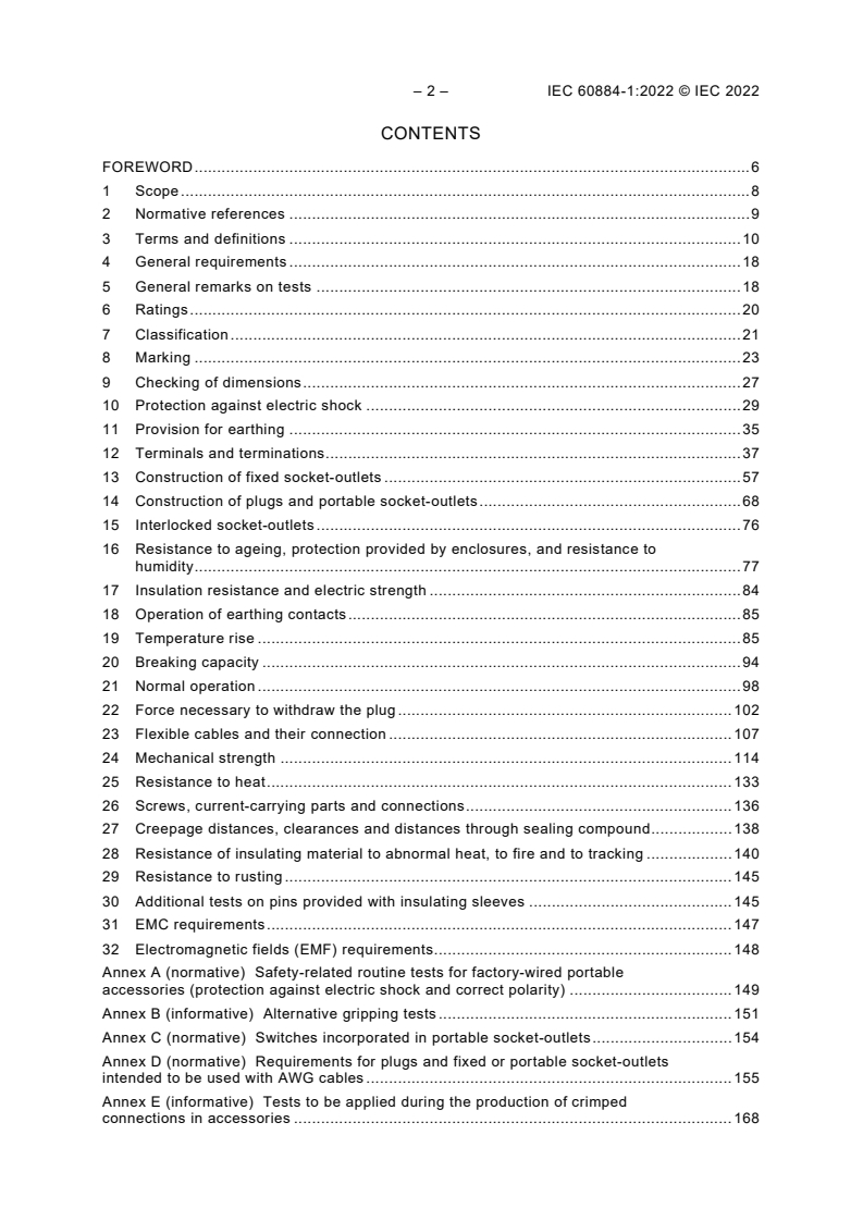
CONTENTS
FOREWORD . 6
1 Scope . 8
2 Normative references . 9
3 Terms and definitions . 10
4 General requirements . 18
5 General remarks on tests . 18
6 Ratings . 20
7 Classification . 21
8 Marking . 23
9 Checking of dimensions . 27
10 Protection against electric shock . 29
11 Provision for earthing . 35
12 Terminals and terminations . 37
13 Construction of fixed socket-outlets . 57
14 Construction of plugs and portable socket-outlets . 68
15 Interlocked socket-outlets . 76
16 Resistance to ageing, protection provided by enclosures, and resistance to
humidity . 77
17 Insulation resistance and electric strength . 84
18 Operation of earthing contacts . 85
19 Temperature rise . 85
20 Breaking capacity . 94
21 Normal operation . 98
22 Force necessary to withdraw the plug . 102
23 Flexible cables and their connection . 107
24 Mechanical strength . 114
25 Resistance to heat . 133
26 Screws, current-carrying parts and connections . 136
27 Creepage distances, clearances and distances through sealing compound . 138
28 Resistance of insulating material to abnormal heat, to fire and to tracking . 140
29 Resistance to rusting . 145
30 Additional tests on pins provided with insulating sleeves . 145
31 EMC requirements . 147
32 Electromagnetic fields (EMF) requirements . 148
Annex A (normative) Safety-related routine tests for factory-wired portable
accessories (protection against electric shock and correct polarity) . 149
Annex B (informative) Alternative gripping tests . 151
Annex C (normative) Switches incorporated in portable socket-outlets . 154
Annex D (normative) Requirements for plugs and fixed or portable socket-outlets
intended to be used with AWG cables . 155
Annex E (informative) Tests to be applied during the production of crimped
connections in accessories . 168
Annex F (normative) Additional requirements for accessories provided with insulation-
piercing terminals . 170
Annex G (informative) Additional tests and requirements for accessories intended to
be used in ambient temperatures below −5 °C down to and including −45 °C . 180
Annex H (informative) Additional tests and requirements for accessories intended to
be used in ambient temperatures above +40 °C up to and including +70 °C . 185
Annex I (normative) Additional requirements and tests for plugs and socket-outlets for
high-load (HL) application . 188
Bibliography . 195
Figure 1 – Examples of accessories . 11
Figure 2 – Example of thread-forming screw . 14
Figure 3 – Example of thread-cutting screw . 14
Figure 4 – Examples of membranes and grommets . 16
Figure 5 – Test piston dimensions. 27
Figure 6 – Arrangement for compression test . 30
Figure 7 – Gauge for checking non-accessibility of live parts, through shutters . 33
Figure 8 – Gauge for checking non-accessibility of live parts, through shutters, and of
live parts of socket-outlets with increased protection. 34
Figure 9 – Pillar terminals . 40
Figure 10 – Screw head terminals and stud terminals . 42
Figure 11 – Saddle terminals . 42
Figure 12 – Mantle terminals . 43
Figure 13 – Arrangement for checking damage to conductors . 44
Figure 14 – Information for deflection test . 55
Figure 15 – Verification of the requirements of 13.4 . 61
Figure 16 – Device for checking the resistance to lateral strain . 65
Figure 17 – Device for testing pins which are not solid . 69
Figure 18 – Types of test wall . 81
Figure 19 – Test set-up in accordance with 16.2.3 . 82
Figure 20 – Clamping unit for the temperature rise test of Clause 19 . 89
Figure 21 – Example of a trend line calculation . 94
Figure 22 – Example of apparatus for breaking capacity and normal operation test . 96
Figure 23 – Circuit diagrams for breaking capacity and normal operation tests . 97
Figure 24 – Test procedures for normal operation for socket-outlets with shutters (see
Clause 21) . 101
Figure 25 – Apparatus for verification of maximum withdrawal force . 104
Figure 26 – Gauge for the verification of minimum withdrawal force . 105
Figure 27 – Apparatus for testing cord retention. 108
Figure 28 – Apparatus for flexing test . 113
Figure 29 – Sketches showing the application of the blows according to Table 23. 118
Figure 30 – Apparatus for impact test at low temperature of 24.5 . 121
Figure 31 – Apparatus for abrasion test on insulating sleeves of plug pins . 122
Figure 32 – Arrangement for mechanical strength test on multiple portable socket-
outlets . 124
– 4 – IEC 60884-1:2022 © IEC 2022
Figure 33 – Example of test arrangement to verify the retention of pins in the body of
the plug . 125
Figure 34 – Arrangement for test on covers or cover-plates . 128
Figure 35 – Gauge (thickness about 2 mm) for the verification of the outline of covers
or cover-plates . 129
Figure 36 – Examples of application of the gauge of Figure 35 on covers fixed without
screws on a mounting surface or supporting surface . 130
Figure 37 – Examples of application of the gauge of Figure 35 in accordance with the
requirements of 24.16 . 131
Figure 38 – Gauge for verification of grooves, holes and reverse tapers . 132
Figure 39 – Sketch showing the direction of application of the gauge of Figure 38 . 132
Figure 40 – Ball pressure test apparatus . 134
Figure 41 – Apparatus for compression test for the verification of resistance to
heat specification of 25.5 . 135
Figure 42 – Diagrammatic representation of 28.1.2 . 142
Figure 43 – Apparatus for testing resistance to abnormal heat of insulating sleeves of
plug pins . 144
Figure 44 – Apparatus for pressure test at high temperature . 146
Figure 45 – Impact test apparatus on pins provided with insulating sleeves . 147
Figure B.1 – Reference plug for gripping test . 152
Figure B.2 – Example of the test apparatus for plug gripping test . 153
Figure F.1 – Example of IPTs . 178
Figure F.2 – Example of test-points . 178
Figure F.3 – Temperature cycle for voltage drop test 12.4.11 . 179
Figure H.1 – Schematic drawing of a de-rating curve with an example of a de-rated
current I at the operating ambient temperature t . 186
d d
Table 1 – Survey of specimens needed for tests . 19
Table 2 – Preferred combinations of types and ratings . 21
Table 3 – Gauge tolerances . 28
Table 4 – Relationship between rated current and connectable nominal cross-sectional
areas of copper conductors . 38
Table 5 – Values for pull test for screw-type terminals . 45
Table 6 – Composition of conductors . 46
Table 7 – Tightening torques for the verification of the mechanical strength of screw-
type terminals . 48
Table 8 – Relationship between rated current and connectable cross-sectional areas of
copper conductors for screwless-type terminals . 49
Table 9 – Value for pull test for screwless-type-type terminals . 51
Table 10 – Values for flexing under mechanical load test for copper conductors . 52
Table 11 – Test current for the verification of electrical and thermal stresses in normal
use for screwless-type terminals . 52
Table 12 – Nominal cross-sectional areas of rigid copper conductors for deflection test
of screwless-type terminals . 55
Table 13 – Deflection test forces for screwless-type terminals . 56
Table 14 – Forces to be applied to covers, cover-plates or actuating members whose
fixing is not dependent on screws . 63
Table 15 – External cable dimension limits for surface-type socket-outlets . 67
Table 16 – Nominal cross-sectional areas of copper conductors for the temperature-
rise test . 86
Table 17 – Test current for cycling tests on accessories with crimped connection . 93
Table 18 – Relationship between rating of accessories, nominal cross-sectional areas
of test conductors and test currents for the tests of temperature rise (Clause 19) and
normal operation (Clause 21) . 99
Table 19 – Maximum and minimum withdrawal force for plugs and socket-outlets . 106
Table 20 – External dimensions of flexible cables to be accommodated by cord
anchorages . 109
Table 21 – Torque test values for cord anchorages . 110
Table 22 – Maximum dimensions of flexible cables to be accommodated in rewirable
accessories . 111
Table 23 – Height of fall for impact tests . 116
Table 24 – Torque test values for cable glands . 122
Table 25 – Resistance to heat of different types or parts of accessories . 133
Table 26 – Creepage distances, clearances and distances through insulating sealing
compound . 139
Table A.1 – Diagrammatic representation of routine tests to be applied to factory-wired
portable accessories . 150
Table F.1 – Relationship between rated currents and connectable cross-sectional
areas of copper conductors for IPTs . 173
Table F.2 – Test current for the verification of electrical and thermal stresses in normal
use of IPTs . 177
Table G.1 – Energy for impact tests . 183
Table I.1 – Test current for cycling tests on plugs . 192
– 6 – IEC 60884-1:2022 © IEC 2022
INTERNATIONAL ELECTROTECHNICAL COMMISSION
____________
PLUGS AND SOCKET-OUTLETS FOR
HOUSEHOLD AND SIMILAR PURPOSES –
Part 1: General requirements
FOREWORD
1) The International Electrotechnical Commission (IEC) is a worldwide organization for standardization comprising
all national electrotechnical committees (IEC National Committees). The object of IEC is to promote international
co-operation on all questions concerning standardization in the electrical and electronic fields. To this end and
in addition to other activities, IEC publishes International Standards, Technical Specifications, Technical Reports,
Publicly Available Specifications (PAS) and Guides (hereafter referred to as “IEC Publication(s)”). Their
preparation is entrusted to technical committees; any IEC National Committee interested in the subject dealt with
may participate in this preparatory work. International, governmental and non-governmental organizations liaising
with the IEC also participate in this preparation. IEC collaborates closely with the International Organization for
Standardization (ISO) in accordance with conditions determined by agreement between the two organizations.
2) The formal decisions or agreements of IEC on technical matters express, as nearly as possible, an international
consensus of opinion on the relevant subjects since each technical committee has representation from all
interested IEC National Committees.
3) IEC Publications have the form of recommendations for international use and are accepted by IEC National
Committees in that sense. While all reasonable efforts are made to ensure that the technical content of IEC
Publications is accurate, IEC cannot be held responsible for the way in which they are used or for any
misinterpretation by any end user.
4) In order to promote international uniformity, IEC National Committees undertake to apply IEC Publications
transparently to the maximum extent possible in their national and regional publications. Any divergence between
any IEC Publication and the corresponding national or regional publication shall be clearly indicated in the latter.
5) IEC itself does not provide any attestation of conformity. Independent certification bodies provide conformity
assessment services and, in some areas, access to IEC marks of conformity. IEC is not responsible for any
services carried out by independent certification bodies.
6) All users should ensure that they have the latest edition of this publication.
7) No liability shall attach to IEC or its directors, employees, servants or agents including individual experts and
members of its technical committees and IEC National Committees for any personal injury, property damage or
other damage of any nature whatsoever, whether direct or indirect, or for costs (including legal fees) and
expenses arising out of the publication, use of, or reliance upon, this IEC Publication or any other IEC
Publications.
8) Attention is drawn to the Normative references cited in this publication. Use of the referenced publications is
indispensable for the correct application of this publication.
9) Attention is drawn to the possibility that some of the elements of this IEC Publication may be the subject of patent
rights. IEC shall not be held responsible for identifying any or all such patent rights.
IEC 60884-1 has been prepared by subcommittee 23B: Plugs, socket-outlets and switches, of
IEC technical committee 23: Electrical accessories. It is an International Standard.
This fourth edition cancels and replaces the third edition published in 2002, Amendment 1:2006
and Amendment 2:2013. This edition constitutes a technical revision.
This edition includes the following significant technical changes with respect to the previous
edition:
a) plugs and socket-outlets incorporating pilot lights;
b) crimped connections in accessories;
c) insulation piercing terminals (IPT);
d) accessories to be used with American Wire Gauge (AWG) cables;
e) accessories used in T° below −5 °C down to and including −45 °C;
f) accessories used in T° above +40 °C up to and including +70 °C;
g) plugs and socket-outlets for high load (HL);
h) clarification of some definitions;
i) durability of markings test;
j) introduction of thermal monitoring in the plug;
k) requirements for shutters in portable socket-outlets;
l) test walls for the verification of ingress of water;
m) rewriting of the temperature rise clause.
The text of this International Standard is based on the following documents:
Draft Report on voting
23B/1386/FDIS 23B/1400/RVD
Full information on the voting for its approval can be found in the report on voting indicated in
the above table.
The language used for the development of this International Standard is English.
This document was drafted in accordance with ISO/IEC Directives, Part 2, and developed in
accordance with ISO/IEC Directives, Part 1 and ISO/IEC Directives, IEC Supplement, available
at www.iec.ch/members_experts/refdocs. The main document types developed by IEC are
described in greater detail at www.iec.ch/standardsdev/publications.
A list of all parts in the IEC 60884 series, published under the general title Plugs and
socket-outlets for household and similar purposes, can be found on the IEC website.
The following print types are used:
– requirements: in roman type;
– test specifications: in italic type;
– notes: in small roman type.
The committee has decided that the contents of this document will remain unchanged until the
stability date indicated on the IEC website under "http://webstore.iec.ch" in the data related to
the specific document. At this date, the document will be
• reconfirmed,
• withdrawn,
• replaced by a revised edition, or
• amended.
IMPORTANT – The 'colour inside' logo on the cover page of this publication indicates
that it contains colours which are considered to be useful for the correct understanding
of its contents. Users should therefore print this document using a colour printer.
– 8 – IEC 60884-1:2022 © IEC 2022
PLUGS AND SOCKET-OUTLETS FOR
HOUSEHOLD AND SIMILAR PURPOSES –
Part 1: General requirements
1 Scope
This part of IEC 60884 applies to plugs and fixed or portable socket-outlets for AC only, with or
without earthing contact, with a rated voltage greater than 50 V but not exceeding 440 V and a
rated current not exceeding 32 A, intended for household and similar purposes, either indoors
or outdoors.
Compatible plugs and socket-outlets, when combined, form a plug and socket-outlet system.
Standardized systems used around the world are reported in IEC/TR 60083.
The rated current is limited to 16 A maximum for accessories provided with screwless-type
terminals.
This document covers only those requirements for mounting boxes which are necessary for the
tests on the socket-outlet.
NOTE 1 Requirements for general purpose mounting boxes are given in IEC 60670-1.
This document also applies to:
– plugs which are a part of cord sets;
– plugs and portable socket-outlets which are a part of cord extension sets;
– plugs and socket-outlets which are a component of an appliance, unless otherwise stated
in the standard for the relevant appliance; and
– plugs and socket-outlets incorporating pilot lights.
This document does not apply to:
– plugs, socket-outlets and couplers for industrial purposes;
– appliance couplers;
– plugs, fixed and portable socket-outlets for extra low voltage (ELV);
NOTE 2 ELV values are specified in IEC 60364-4-41.
– fixed socket-outlets combined with fuses, automatic switches, etc.
Plugs of this document are intended to be energised by socket-outlets.
NOTE 3 Use in any other manner could result in unsafe conditions within the installation if proper precautions are
not taken. When energy producing equipment is connected to the fixed installation via plugs of this document all
safety aspects of the products and the installation need to be evaluated by the manufacturer of the energy producing
equipment.
Plugs and socket-outlets complying with this document are suitable for use at ambient
temperatures not normally exceeding +40 °C, but their average temperature over a period of
24 h does not exceed +35 °C, with a lower limit of the ambient air temperature of −5 °C.
In locations where special conditions prevail, such as in ships, vehicles and the like and in
hazardous locations, for example where explosions are liable to occur, additional requirements
can be applicable.
This document gives additional requirements for accessories intended to be used with AWG
cables, see Annex D (normative).
This document gives additional tests to be applied during the production of crimped connections
in accessories, see Annex E (informative).
This document gives additional requirements for accessories provided with insulation-piercing
terminals, see Annex F (normative).
This document gives additional specifications for accessories intended to be used in ambient
temperatures below −5 °C down to and including −45 °C, see Annex G (informative).
This document gives additional specifications for accessories intended to be used in ambient
temperatures above +40 °C up to and including +70 °C, see Annex H (informative).
This document gives additional requirements for plugs and socket-outlets for high load (HL).
These plugs and socket-outlets are typically intended to be used for loads applying long and
repetitive cycles up to the rated current of the accessories, see Annex I (normative).
2 Normative references
The following documents are referred to in the text in such a way that some or all of their content
constitutes requirements of this document. For dated references, only the edition cited applies.
For undated references, the latest edition of the referenced document (including any
amendments) applies.
IEC 60068-2-30, Environmental testing – Part 2-30: Tests – Test Db: Damp heat, cyclic
(12 + 12 h cycle)
IEC 60068-2-31, Environmental testing – Part 2-31: Tests – Test Ec: Rough handling shocks,
primarily for equipment-type specimens
IEC 60068-2-75, Environmental testing – Part 2-75: Tests – Test Eh: Hammer tests
IEC 60112, Method for the determination of the proof and the comparative tracking indices of
solid insulating materials
IEC 60227 (all parts), Polyvinyl chloride insulated cables of rated voltages up to and including
450/750 V
IEC 60245 (all parts), Rubber insulated cables – Rated voltages up to and including 450/750 V
IEC 60417, Graphical symbols for use on equipment (available at http://www.graphical-
symbols.info/equipment)
IEC 60423:2007, Conduit systems for cable management – Outside diameters of conduits for
electrical installations and threads for conduits and fittings
IEC 60529:1989, Degrees of protection provided by enclosures (IP Code)
IEC 60529:1989/AMD1:1999
IEC 60529:1989/AMD2:2013
IEC 60669 (all parts), Switches for household and similar fixed-electrical installations
IEC 60669-2-1:2021, Switches for household and similar fixed electrical installations – Part 2-1:
Particular requirements – Electronic control devices
– 10 – IEC 60884-1:2022 © IEC 2022
IEC 60695-2-10:2021, Fire hazard testing – Part 2-10: Glowing/hot-wire based test methods –
Glow-wire apparatus and common test procedure
IEC 60695-2-11:2021, Fire hazard testing – Part 2-11: Glowing/hot-wire based test methods –
Glow-wire flammability test method for end products (GWEPT)
IEC 60884-2-1, Plugs and socket-outlets for household and similar purposes – Part 2-1:
Particular requirements for fused plugs
IEC 61032:1997, Protection of persons and equipment by enclosures – Probes for verification
IEC 61058 (all parts), Switches for appliances
IEC 61545, Connecting devices – Devices for the connection of aluminium conductors in
clamping units of any material and copper conductors in aluminium bodied clamping units
ISO/IEC Guide 51, Safety aspects – Guidelines for their inclusion in standards
ISO 1456:2009, Metallic and other inorganic coatings – Electrodeposited coatings of nickel,
nickel plus chromium, copper plus nickel and of copper plus nickel plus chromium
ISO 2081:2018, Metallic and other inorganic coatings – Electroplated coatings of zinc with
supplementary treatments on iron or steel
ISO 2093:1986, Electroplated coatings of tin – Specification and test methods
3 Terms and definitions
For the purposes of this document, the following terms and definitions apply.
ISO and IEC maintain terminological databases for use in standardization at the following
addresses:
• IEC Electropedia: available at http://www.electropedia.org/
• ISO Online browsing platform: available at http://www.iso.org/obp
NOTE 1 Where the terms "voltage" and "current" are used, they imply RMS values, unless otherwise specified.
NOTE 2 Throughout this document the word "earthing" is used for "protective earthing" unless otherwise stated.
NOTE 3 The term "accessory" is used as a general term covering plugs and socket-outlets; the term "portable
accessory" covers plugs and portable socket-outlets. Examples of the use of accessories are shown in Figure 1 a).
NOTE 4 Throughout this document the term "socket-outlet" covers both fixed and portable socket-outlets, except
where the reference is specific to one type or the other.
a) Diagram showing various accessories and their use
NOTE Appliance, appliance inlet and appliance coupler are used in this figure only for illustration purposes and
they are not covered by this document.
b) Example of a multiple socket-outlet
Figure 1 – Examples of accessories
3.1
plug
accessory having pins designed to engage with the contacts of a socket-outlet
Note 1 to entry: A plug allows the manual connection and disconnection of an electrical load to an electrical supply
by an ordinary person.
Note 2 to entry: The plug can be connected to a cable or integrated into an accessory.
Note 3 to entry: In adaptors, the plug can be integral or detachable, see IEC 60884-2-5.
Note 4 to entry: For special purposes such as lighting chains (see also IEC 60598-2-20), two or three single-core
cables can be connected within the plug.
3.2
socket-outlet
accessory having socket-contacts designed to engage with the pins of a plug
Note 1 to entry: The socket-outlet can be connected to a cable or integrated into an accessory.
Note 2 to entry: In adaptors, the socket-outlet can be integral or detachable, see IEC 60884-2-5.
3.3
fixed socket-outlet
socket-outlet intended to be installed at a fixed location and be connected to fixed wiring
– 12 – IEC 60884-1:2022 © IEC 2022
3.4
portable socket-outlet
socket-outlet intended to be connected to or integral with one flexible cable and which can
easily be moved from one place to another while connected to the supply
3.5
multiple socket-outlets
combination of two or more socket-outlets
Note 1 to entry: An example is shown in Figure 1 b).
3.6
rewirable plug
plug so constructed that the flexible cable can be replaced
3.7
non-rewirable plug
assembly of the plug and the flexible cable so constructed that the flexible cable cannot be
replaced
3.8
rewirable portable socket-outlet
socket-outlet so constructed that the flexible cable can be replaced
3.9
non-rewirable portable socket-outlet
assembly of the socket-outlet and the flexible cable so constructed that the flexible cable cannot
be replaced
3.10
moulded-on accessory
non-rewirable portable accessory the manufacture of which is completed by insulating material
moulded around pre-assembled component parts and the terminations for the flexible cable
[SOURCE: IEC 60050-442:1998, 442-01-14, modified – "portable" has been added to the
definition and "or cord" has been omitted.]
3.11
mounting box
box intended for mounting in or on a wall, floor or ceiling, etc., for flush or surface application,
intended for use with fixed socket-outlet(s)
3.12
cord set
assembly consisting of a flexible cable or cord fitted with a non-rewirable plug and a non-
rewirable connector, intended for the connection of an electrical appliance to the electrical
supply
[SOURCE: IEC 60050-442:1998, 442-07-04, and IEC 60050-442:2008, 461-06-16]
3.13
cord extension set
assembly consisting of one flexible cable fitted with one plug and one single or multiple portable
socket-outlets
3.14
terminal
insulated or non-insulated connecting device intended for reusable electrical connection of the
external conductors
3.15
termination
insulated or non-insulated connecting device intended for non-reusable electrical connection of
the external conductors
3.16
clamping unit
part(s) of the terminal necessary for the mechanical clamping and the electrical connection of
the conductor(s), including the parts which are necessary to ensure correct contact pressure
[SOURCE: IEC 60050-442:1998, 442-06-12]
3.17
screw-type terminal
terminal for the connection and subsequent disconnection of one conductor or the
interconnection and subsequent disconnection of two or more conductors, the connection being
made, directly or indirectly, by means of screws or nuts of any kind
Note 1 to entry: Term entries 3.18 to 3.23 are examples of screw-type terminals.
3.18
pillar terminal
screw-type terminal in which the conductor is inserted into a hole or cavity, where it is clamped
under the end of the screw or screws
Note 1 to entry: The clamping pressure may be applied directly by the end of the screw or through an intermediate
clamping member to which pressure is applied by the end of the screw.
Note 2 to entry: Examples of pillar terminals are shown in Figure 9.
3.19
stirrup terminal
pillar terminal where the clamping pressure may be applied indirectly by an intermediate
clamping member when the screw is tightened
Note 1 to entry: Examples of stirrup terminals are shown in Figure 9.
3.20
screw head terminal
screw-type terminal in which the conductor is clamped under the head of the screw
Note 1 to entry: The clamping pressure may be applied directly to the head of a screw or through an intermediate
part, such as a washer, clamping plate or anti-spread device.
Note 2 to entry: Examples of screw head terminals are shown in Figure 10.
3.21
stud terminal
screw-type terminal in which the conductor is clamped under a nut
Note 1 to entry: The clamping pressure may be applied directly by a suitably shaped nut or through an intermediate
part, such as a washer, clamping plate or anti-spread device.
Note 2 to entry: Examples of stud terminals are shown in Figure 10.
– 14 – IEC 60884-1:2022 © IEC 2022
3.22
saddle terminal
screw-type terminal in which the conductor is clamped under a saddle by means of two or more
screws or nuts
Note 1 to entry: Examples of saddle terminals are shown in Figure 11.
3.23
mantle terminal
screw-type terminal in which the conductor is clamped against the base of a slot in a threaded
stud by means of a nut
Note 1 to entry: The conductor is clamped against the base of the slot by a suitably shaped washer under the nut,
by a central peg if the nut is a cap nut, or by equally effective means for transmitting the pressure from the nut to the
conductor within the slot.
Note 2 to entry: Examples of mantle terminals are shown in Figure 12.
3.24
screwless-type terminal
connecting device for the connection and subsequent disconnection of a rigid (solid or stranded)
or flexible conductor or the interconnection of two or more conductors, capable of being
dismantled, the connection being made, directly or indirectly, by means of springs, parts of
angled, eccentric or conical form, etc., without special preparation of the conductor concerned,
other than removal of insulation
3.25
thread-forming screw
screw having an uninterrupted thread, which by screwing in, forms a thread by displacing
material
Note 1 to entry: An example of a thread-forming screw is shown in Figure 2.
Figure 2 – Example of thread-forming screw
3.26
thread-cutting screw
screw having an interrupted thread, which by screwing in, forms a thread by removing material
Note 1 to entry: An example of a thread-cutting screw is shown in Figure 3.
Figure 3 – Example of thread-cutting screw
3.27
rated voltage
voltage assigned by the manufacturer for a specified operating condition of an accessory
[SOURCE: IEC 60050-442:1998, 442-01-03, modified – The domain "(for accessories)" has
been omitted.]
3.28
rated current
current assigned by the manufacturer for specified operating condition of an accessory
Note 1 to entry: Examples of the operating conditions are ambient condition, characteristics of the power supply,
duty cycle or duty type.
[SOURCE: IEC 60050-442:1998, 442-01-02, modified – The domain "(for accessories)" has
been omitted and the note to entry added.]
3.29
shutter
movable part incorporated into a socket-outlet arranged to shield at least the live
socket-contacts automatically when the plug is withdrawn
3.30
type test
test of one or more devices made to a certain design to show that the design meets certain
specifications
3.31
routine test
test to which each individual device is subjected during and/or after manufacture to ascertain
whether it complies with certain criteria
3.32
base
part of the socket-outlet supporting the socket-contacts
3.33
live part
conductor or conductive part intended to be energized in normal use, including a neutral
conductor, but by convention not a PEN conductor
Note 1 to entry: Live parts according to this document are always considered as hazardous with the exception of
SELV circuits.
[SOURCE: IEC 60050-826:2004, 826-12-08, modified – "operation" has been replaced with
"use"; "or PEM conductor or PEL conductor" and the note to entry omitted.]
3.34
cable anchorage
part of an accessory which has the ability to limit the displacement of a fitted flexible cable
against pull, push and turning forces
3.35
main part
assembly consisting of the base and other parts
Note 1 to entry: This assembly is not intended to be dismantled at any time after manufacture.
3.36
grommet
component used to support and protect the cable or conduit at the point of entry
Note 1 to entry: A grommet may als
...
IEC 60884-1 ®
Edition 4.0 2022-08
INTERNATIONAL
STANDARD
NORME
INTERNATIONALE
colour
inside
Plugs and socket-outlets for household and similar purposes –
Part 1: General requirements
Prises de courant pour usages domestiques et analogues –
Partie 1: Exigences générales
All rights reserved. Unless otherwise specified, no part of this publication may be reproduced or utilized in any form
or by any means, electronic or mechanical, including photocopying and microfilm, without permission in writing from
either IEC or IEC's member National Committee in the country of the requester. If you have any questions about IEC
copyright or have an enquiry about obtaining additional rights to this publication, please contact the address below or
your local IEC member National Committee for further information.
Droits de reproduction réservés. Sauf indication contraire, aucune partie de cette publication ne peut être reproduite ni
utilisée sous quelque forme que ce soit et par aucun procédé, électronique ou mécanique, y compris la photocopie et
les microfilms, sans l'accord écrit de l'IEC ou du Comité national de l'IEC du pays du demandeur. Si vous avez des
questions sur le copyright de l'IEC ou si vous désirez obtenir des droits supplémentaires sur cette publication, utilisez
les coordonnées ci-après ou contactez le Comité national de l'IEC de votre pays de résidence.
IEC Secretariat Tel.: +41 22 919 02 11
3, rue de Varembé info@iec.ch
CH-1211 Geneva 20 www.iec.ch
Switzerland
About the IEC
The International Electrotechnical Commission (IEC) is the leading global organization that prepares and publishes
International Standards for all electrical, electronic and related technologies.
About IEC publications
The technical content of IEC publications is kept under constant review by the IEC. Please make sure that you have the
latest edition, a corrigendum or an amendment might have been published.
IEC publications search - webstore.iec.ch/advsearchform IEC Products & Services Portal - products.iec.ch
The advanced search enables to find IEC publications by a Discover our powerful search engine and read freely all the
variety of criteria (reference number, text, technical publications previews. With a subscription you will always have
committee, …). It also gives information on projects, replaced access to up to date content tailored to your needs.
and withdrawn publications.
Electropedia - www.electropedia.org
IEC Just Published - webstore.iec.ch/justpublished
The world's leading online dictionary on electrotechnology,
Stay up to date on all new IEC publications. Just Published
containing more than 22 300 terminological entries in English
details all new publications released. Available online and once
and French, with equivalent terms in 19 additional languages.
a month by email.
Also known as the International Electrotechnical Vocabulary
(IEV) online.
IEC Customer Service Centre - webstore.iec.ch/csc
If you wish to give us your feedback on this publication or need
further assistance, please contact the Customer Service
Centre: sales@iec.ch.
A propos de l'IEC
La Commission Electrotechnique Internationale (IEC) est la première organisation mondiale qui élabore et publie des
Normes internationales pour tout ce qui a trait à l'électricité, à l'électronique et aux technologies apparentées.
A propos des publications IEC
Le contenu technique des publications IEC est constamment revu. Veuillez vous assurer que vous possédez l’édition la
plus récente, un corrigendum ou amendement peut avoir été publié.
Recherche de publications IEC - Découvrez notre puissant moteur de recherche et consultez
webstore.iec.ch/advsearchform gratuitement tous les aperçus des publications. Avec un
La recherche avancée permet de trouver des publications IEC abonnement, vous aurez toujours accès à un contenu à jour
en utilisant différents critères (numéro de référence, texte, adapté à vos besoins.
comité d’études, …). Elle donne aussi des informations sur les
projets et les publications remplacées ou retirées. Electropedia - www.electropedia.org
Le premier dictionnaire d'électrotechnologie en ligne au monde,
IEC Just Published - webstore.iec.ch/justpublished
avec plus de 22 300 articles terminologiques en anglais et en
Restez informé sur les nouvelles publications IEC. Just
français, ainsi que les termes équivalents dans 19 langues
Published détaille les nouvelles publications parues.
additionnelles. Egalement appelé Vocabulaire
Disponible en ligne et une fois par mois par email.
Electrotechnique International (IEV) en ligne.
Service Clients - webstore.iec.ch/csc
Si vous désirez nous donner des commentaires sur cette
publication ou si vous avez des questions contactez-nous:
sales@iec.ch.
IEC Products & Services Portal - products.iec.ch
IEC 60884-1 ®
Edition 4.0 2022-08
INTERNATIONAL
STANDARD
NORME
INTERNATIONALE
colour
inside
Plugs and socket-outlets for household and similar purposes –
Part 1: General requirements
Prises de courant pour usages domestiques et analogues –
Partie 1: Exigences générales
INTERNATIONAL
ELECTROTECHNICAL
COMMISSION
COMMISSION
ELECTROTECHNIQUE
INTERNATIONALE
ICS 29.120.30 ISBN 978-2-8322-6058-6
– 2 – IEC 60884-1:2022 © IEC 2022
CONTENTS
FOREWORD . 6
1 Scope . 8
2 Normative references . 9
3 Terms and definitions . 10
4 General requirements . 18
5 General remarks on tests . 18
6 Ratings . 20
7 Classification . 21
8 Marking . 23
9 Checking of dimensions . 27
10 Protection against electric shock . 29
11 Provision for earthing . 35
12 Terminals and terminations . 37
13 Construction of fixed socket-outlets . 57
14 Construction of plugs and portable socket-outlets . 68
15 Interlocked socket-outlets . 76
16 Resistance to ageing, protection provided by enclosures, and resistance to
humidity . 77
17 Insulation resistance and electric strength . 84
18 Operation of earthing contacts . 85
19 Temperature rise . 85
20 Breaking capacity . 94
21 Normal operation . 98
22 Force necessary to withdraw the plug . 102
23 Flexible cables and their connection . 107
24 Mechanical strength . 114
25 Resistance to heat . 133
26 Screws, current-carrying parts and connections . 136
27 Creepage distances, clearances and distances through sealing compound . 138
28 Resistance of insulating material to abnormal heat, to fire and to tracking . 140
29 Resistance to rusting . 145
30 Additional tests on pins provided with insulating sleeves . 145
31 EMC requirements . 147
32 Electromagnetic fields (EMF) requirements . 148
Annex A (normative) Safety-related routine tests for factory-wired portable
accessories (protection against electric shock and correct polarity) . 149
Annex B (informative) Alternative gripping tests . 151
Annex C (normative) Switches incorporated in portable socket-outlets . 154
Annex D (normative) Requirements for plugs and fixed or portable socket-outlets
intended to be used with AWG cables . 155
Annex E (informative) Tests to be applied during the production of crimped
connections in accessories . 168
Annex F (normative) Additional requirements for accessories provided with insulation-
piercing terminals . 170
Annex G (informative) Additional tests and requirements for accessories intended to
be used in ambient temperatures below −5 °C down to and including −45 °C . 180
Annex H (informative) Additional tests and requirements for accessories intended to
be used in ambient temperatures above +40 °C up to and including +70 °C . 185
Annex I (normative) Additional requirements and tests for plugs and socket-outlets for
high-load (HL) application . 188
Bibliography . 195
Figure 1 – Examples of accessories . 11
Figure 2 – Example of thread-forming screw . 14
Figure 3 – Example of thread-cutting screw . 14
Figure 4 – Examples of membranes and grommets . 16
Figure 5 – Test piston dimensions. 27
Figure 6 – Arrangement for compression test . 30
Figure 7 – Gauge for checking non-accessibility of live parts, through shutters . 33
Figure 8 – Gauge for checking non-accessibility of live parts, through shutters, and of
live parts of socket-outlets with increased protection. 34
Figure 9 – Pillar terminals . 40
Figure 10 – Screw head terminals and stud terminals . 41
Figure 11 – Saddle terminals . 42
Figure 12 – Mantle terminals . 43
Figure 13 – Arrangement for checking damage to conductors . 44
Figure 14 – Information for deflection test . 55
Figure 15 – Verification of the requirements of 13.4 . 61
Figure 16 – Device for checking the resistance to lateral strain . 65
Figure 17 – Device for testing pins which are not solid . 69
Figure 18 – Types of test wall . 81
Figure 19 – Test set-up in accordance with 16.2.3 . 82
Figure 20 – Clamping unit for the temperature rise test of Clause 19 . 89
Figure 21 – Example of a trend line calculation . 94
Figure 22 – Example of apparatus for breaking capacity and normal operation test . 96
Figure 23 – Circuit diagrams for breaking capacity and normal operation tests . 97
Figure 24 – Test procedures for normal operation for socket-outlets with shutters (see
Clause 21) . 101
Figure 25 – Apparatus for verification of maximum withdrawal force . 104
Figure 26 – Gauge for the verification of minimum withdrawal force . 105
Figure 27 – Apparatus for testing cord retention. 108
Figure 28 – Apparatus for flexing test . 113
Figure 29 – Sketches showing the application of the blows according to Table 23. 118
Figure 30 – Apparatus for impact test at low temperature of 24.5 . 121
Figure 31 – Apparatus for abrasion test on insulating sleeves of plug pins . 122
Figure 32 – Arrangement for mechanical strength test on multiple portable socket-
outlets . 124
– 4 – IEC 60884-1:2022 © IEC 2022
Figure 33 – Example of test arrangement to verify the retention of pins in the body of
the plug . 125
Figure 34 – Arrangement for test on covers or cover-plates . 128
Figure 35 – Gauge (thickness about 2 mm) for the verification of the outline of covers
or cover-plates . 129
Figure 36 – Examples of application of the gauge of Figure 35 on covers fixed without
screws on a mounting surface or supporting surface . 130
Figure 37 – Examples of application of the gauge of Figure 35 in accordance with the
requirements of 24.16 . 131
Figure 38 – Gauge for verification of grooves, holes and reverse tapers . 132
Figure 39 – Sketch showing the direction of application of the gauge of Figure 38 . 132
Figure 40 – Ball pressure test apparatus . 134
Figure 41 – Apparatus for compression test for the verification of resistance to
heat specification of 25.5 . 135
Figure 42 – Diagrammatic representation of 28.1.2 . 142
Figure 43 – Apparatus for testing resistance to abnormal heat of insulating sleeves of
plug pins . 144
Figure 44 – Apparatus for pressure test at high temperature . 146
Figure 45 – Impact test apparatus on pins provided with insulating sleeves . 147
Figure B.1 – Reference plug for gripping test . 152
Figure B.2 – Example of the test apparatus for plug gripping test . 153
Figure F.1 – Example of IPTs . 178
Figure F.2 – Example of test-points . 178
Figure F.3 – Temperature cycle for voltage drop test 12.4.11 . 179
Figure H.1 – Schematic drawing of a de-rating curve with an example of a de-rated
current I at the operating ambient temperature t . 186
d d
Table 1 – Survey of specimens needed for tests . 19
Table 2 – Preferred combinations of types and ratings . 21
Table 3 – Gauge tolerances . 28
Table 4 – Relationship between rated current and connectable nominal cross-sectional
areas of copper conductors . 38
Table 5 – Values for pull test for screw-type terminals . 45
Table 6 – Composition of conductors . 46
Table 7 – Tightening torques for the verification of the mechanical strength of screw-
type terminals . 48
Table 8 – Relationship between rated current and connectable cross-sectional areas of
copper conductors for screwless-type terminals . 49
Table 9 – Value for pull test for screwless-type-type terminals . 51
Table 10 – Values for flexing under mechanical load test for copper conductors . 52
Table 11 – Test current for the verification of electrical and thermal stresses in normal
use for screwless-type terminals . 52
Table 12 – Nominal cross-sectional areas of rigid copper conductors for deflection test
of screwless-type terminals . 55
Table 13 – Deflection test forces for screwless-type terminals . 56
Table 14 – Forces to be applied to covers, cover-plates or actuating members whose
fixing is not dependent on screws . 63
Table 15 – External cable dimension limits for surface-type socket-outlets . 67
Table 16 – Nominal cross-sectional areas of copper conductors for the temperature-
rise test . 86
Table 17 – Test current for cycling tests on accessories with crimped connection . 93
Table 18 – Relationship between rating of accessories, nominal cross-sectional areas
of test conductors and test currents for the tests of temperature rise (Clause 19) and
normal operation (Clause 21) . 99
Table 19 – Maximum and minimum withdrawal force for plugs and socket-outlets . 106
Table 20 – External dimensions of flexible cables to be accommodated by cord
anchorages . 109
Table 21 – Torque test values for cord anchorages . 110
Table 22 – Maximum dimensions of flexible cables to be accommodated in rewirable
accessories . 111
Table 23 – Height of fall for impact tests . 116
Table 24 – Torque test values for cable glands . 122
Table 25 – Resistance to heat of different types or parts of accessories . 133
Table 26 – Creepage distances, clearances and distances through insulating sealing
compound . 139
Table A.1 – Diagrammatic representation of routine tests to be applied to factory-wired
portable accessories . 150
Table F.1 – Relationship between rated currents and connectable cross-sectional
areas of copper conductors for IPTs . 173
Table F.2 – Test current for the verification of electrical and thermal stresses in normal
use of IPTs . 177
Table G.1 – Energy for impact tests . 183
Table I.1 – Test current for cycling tests on plugs . 192
– 6 – IEC 60884-1:2022 © IEC 2022
INTERNATIONAL ELECTROTECHNICAL COMMISSION
____________
PLUGS AND SOCKET-OUTLETS FOR
HOUSEHOLD AND SIMILAR PURPOSES –
Part 1: General requirements
FOREWORD
1) The International Electrotechnical Commission (IEC) is a worldwide organization for standardization comprising
all national electrotechnical committees (IEC National Committees). The object of IEC is to promote international
co-operation on all questions concerning standardization in the electrical and electronic fields. To this end and
in addition to other activities, IEC publishes International Standards, Technical Specifications, Technical Reports,
Publicly Available Specifications (PAS) and Guides (hereafter referred to as “IEC Publication(s)”). Their
preparation is entrusted to technical committees; any IEC National Committee interested in the subject dealt with
may participate in this preparatory work. International, governmental and non-governmental organizations liaising
with the IEC also participate in this preparation. IEC collaborates closely with the International Organization for
Standardization (ISO) in accordance with conditions determined by agreement between the two organizations.
2) The formal decisions or agreements of IEC on technical matters express, as nearly as possible, an international
consensus of opinion on the relevant subjects since each technical committee has representation from all
interested IEC National Committees.
3) IEC Publications have the form of recommendations for international use and are accepted by IEC National
Committees in that sense. While all reasonable efforts are made to ensure that the technical content of IEC
Publications is accurate, IEC cannot be held responsible for the way in which they are used or for any
misinterpretation by any end user.
4) In order to promote international uniformity, IEC National Committees undertake to apply IEC Publications
transparently to the maximum extent possible in their national and regional publications. Any divergence between
any IEC Publication and the corresponding national or regional publication shall be clearly indicated in the latter.
5) IEC itself does not provide any attestation of conformity. Independent certification bodies provide conformity
assessment services and, in some areas, access to IEC marks of conformity. IEC is not responsible for any
services carried out by independent certification bodies.
6) All users should ensure that they have the latest edition of this publication.
7) No liability shall attach to IEC or its directors, employees, servants or agents including individual experts and
members of its technical committees and IEC National Committees for any personal injury, property damage or
other damage of any nature whatsoever, whether direct or indirect, or for costs (including legal fees) and
expenses arising out of the publication, use of, or reliance upon, this IEC Publication or any other IEC
Publications.
8) Attention is drawn to the Normative references cited in this publication. Use of the referenced publications is
indispensable for the correct application of this publication.
9) Attention is drawn to the possibility that some of the elements of this IEC Publication may be the subject of patent
rights. IEC shall not be held responsible for identifying any or all such patent rights.
IEC 60884-1 has been prepared by subcommittee 23B: Plugs, socket-outlets and switches, of
IEC technical committee 23: Electrical accessories. It is an International Standard.
This fourth edition cancels and replaces the third edition published in 2002, Amendment 1:2006
and Amendment 2:2013. This edition constitutes a technical revision.
This edition includes the following significant technical changes with respect to the previous
edition:
a) plugs and socket-outlets incorporating pilot lights;
b) crimped connections in accessories;
c) insulation piercing terminals (IPT);
d) accessories to be used with American Wire Gauge (AWG) cables;
e) accessories used in T° below −5 °C down to and including −45 °C;
f) accessories used in T° above +40 °C up to and including +70 °C;
g) plugs and socket-outlets for high load (HL);
h) clarification of some definitions;
i) durability of markings test;
j) introduction of thermal monitoring in the plug;
k) requirements for shutters in portable socket-outlets;
l) test walls for the verification of ingress of water;
m) rewriting of the temperature rise clause.
The text of this International Standard is based on the following documents:
Draft Report on voting
23B/1386/FDIS 23B/1400/RVD
Full information on the voting for its approval can be found in the report on voting indicated in
the above table.
The language used for the development of this International Standard is English.
This document was drafted in accordance with ISO/IEC Directives, Part 2, and developed in
accordance with ISO/IEC Directives, Part 1 and ISO/IEC Directives, IEC Supplement, available
at www.iec.ch/members_experts/refdocs. The main document types developed by IEC are
described in greater detail at www.iec.ch/standardsdev/publications.
A list of all parts in the IEC 60884 series, published under the general title Plugs and
socket-outlets for household and similar purposes, can be found on the IEC website.
The following print types are used:
– requirements: in roman type;
– test specifications: in italic type;
– notes: in small roman type.
The committee has decided that the contents of this document will remain unchanged until the
stability date indicated on the IEC website under "http://webstore.iec.ch" in the data related to
the specific document. At this date, the document will be
• reconfirmed,
• withdrawn,
• replaced by a revised edition, or
• amended.
IMPORTANT – The 'colour inside' logo on the cover page of this publication indicates
that it contains colours which are considered to be useful for the correct understanding
of its contents. Users should therefore print this document using a colour printer.
The contents of the corrigendum 1 (2023-12) have been included in this copy.
– 8 – IEC 60884-1:2022 © IEC 2022
PLUGS AND SOCKET-OUTLETS FOR
HOUSEHOLD AND SIMILAR PURPOSES –
Part 1: General requirements
1 Scope
This part of IEC 60884 applies to plugs and fixed or portable socket-outlets for AC only, with or
without earthing contact, with a rated voltage greater than 50 V but not exceeding 440 V and a
rated current not exceeding 32 A, intended for household and similar purposes, either indoors
or outdoors.
Compatible plugs and socket-outlets, when combined, form a plug and socket-outlet system.
Standardized systems used around the world are reported in IEC/TR 60083.
The rated current is limited to 16 A maximum for accessories provided with screwless-type
terminals.
This document covers only those requirements for mounting boxes which are necessary for the
tests on the socket-outlet.
NOTE 1 Requirements for general purpose mounting boxes are given in IEC 60670-1.
This document also applies to:
– plugs which are a part of cord sets;
– plugs and portable socket-outlets which are a part of cord extension sets;
– plugs and socket-outlets which are a component of an appliance, unless otherwise stated
in the standard for the relevant appliance; and
– plugs and socket-outlets incorporating pilot lights.
This document does not apply to:
– plugs, socket-outlets and couplers for industrial purposes;
– appliance couplers;
– plugs, fixed and portable socket-outlets for extra low voltage (ELV);
NOTE 2 ELV values are specified in IEC 60364-4-41.
– fixed socket-outlets combined with fuses, automatic switches, etc.
Plugs of this document are intended to be energised by socket-outlets.
NOTE 3 Use in any other manner could result in unsafe conditions within the installation if proper precautions are
not taken. When energy producing equipment is connected to the fixed installation via plugs of this document all
safety aspects of the products and the installation need to be evaluated by the manufacturer of the energy producing
equipment.
Plugs and socket-outlets complying with this document are suitable for use at ambient
temperatures not normally exceeding +40 °C, but their average temperature over a period of
24 h does not exceed +35 °C, with a lower limit of the ambient air temperature of −5 °C.
In locations where special conditions prevail, such as in ships, vehicles and the like and in
hazardous locations, for example where explosions are liable to occur, additional requirements
can be applicable.
This document gives additional requirements for accessories intended to be used with AWG
cables, see Annex D (normative).
This document gives additional tests to be applied during the production of crimped connections
in accessories, see Annex E (informative).
This document gives additional requirements for accessories provided with insulation-piercing
terminals, see Annex F (normative).
This document gives additional specifications for accessories intended to be used in ambient
temperatures below −5 °C down to and including −45 °C, see Annex G (informative).
This document gives additional specifications for accessories intended to be used in ambient
temperatures above +40 °C up to and including +70 °C, see Annex H (informative).
This document gives additional requirements for plugs and socket-outlets for high load (HL).
These plugs and socket-outlets are typically intended to be used for loads applying long and
repetitive cycles up to the rated current of the accessories, see Annex I (normative).
2 Normative references
The following documents are referred to in the text in such a way that some or all of their content
constitutes requirements of this document. For dated references, only the edition cited applies.
For undated references, the latest edition of the referenced document (including any
amendments) applies.
IEC 60068-2-30, Environmental testing – Part 2-30: Tests – Test Db: Damp heat, cyclic
(12 + 12 h cycle)
IEC 60068-2-31, Environmental testing – Part 2-31: Tests – Test Ec: Rough handling shocks,
primarily for equipment-type specimens
IEC 60068-2-75, Environmental testing – Part 2-75: Tests – Test Eh: Hammer tests
IEC 60112, Method for the determination of the proof and the comparative tracking indices of
solid insulating materials
IEC 60227 (all parts), Polyvinyl chloride insulated cables of rated voltages up to and including
450/750 V
IEC 60245 (all parts), Rubber insulated cables – Rated voltages up to and including 450/750 V
IEC 60417, Graphical symbols for use on equipment (available at http://www.graphical-
symbols.info/equipment)
IEC 60423:2007, Conduit systems for cable management – Outside diameters of conduits for
electrical installations and threads for conduits and fittings
IEC 60529:1989, Degrees of protection provided by enclosures (IP Code)
IEC 60529:1989/AMD1:1999
IEC 60529:1989/AMD2:2013
IEC 60669 (all parts), Switches for household and similar fixed-electrical installations
IEC 60669-2-1:2021, Switches for household and similar fixed electrical installations – Part 2-1:
Particular requirements – Electronic control devices
– 10 – IEC 60884-1:2022 © IEC 2022
IEC 60695-2-10:2021, Fire hazard testing – Part 2-10: Glowing/hot-wire based test methods –
Glow-wire apparatus and common test procedure
IEC 60695-2-11:2021, Fire hazard testing – Part 2-11: Glowing/hot-wire based test methods –
Glow-wire flammability test method for end products (GWEPT)
IEC 60884-2-1, Plugs and socket-outlets for household and similar purposes – Part 2-1:
Particular requirements for fused plugs
IEC 61032:1997, Protection of persons and equipment by enclosures – Probes for verification
IEC 61058 (all parts), Switches for appliances
IEC 61545, Connecting devices – Devices for the connection of aluminium conductors in
clamping units of any material and copper conductors in aluminium bodied clamping units
ISO/IEC Guide 51, Safety aspects – Guidelines for their inclusion in standards
ISO 1456:2009, Metallic and other inorganic coatings – Electrodeposited coatings of nickel,
nickel plus chromium, copper plus nickel and of copper plus nickel plus chromium
ISO 2081:2018, Metallic and other inorganic coatings – Electroplated coatings of zinc with
supplementary treatments on iron or steel
ISO 2093:1986, Electroplated coatings of tin – Specification and test methods
3 Terms and definitions
For the purposes of this document, the following terms and definitions apply.
ISO and IEC maintain terminological databases for use in standardization at the following
addresses:
• IEC Electropedia: available at http://www.electropedia.org/
• ISO Online browsing platform: available at http://www.iso.org/obp
NOTE 1 Where the terms "voltage" and "current" are used, they imply RMS values, unless otherwise specified.
NOTE 2 Throughout this document the word "earthing" is used for "protective earthing" unless otherwise stated.
NOTE 3 The term "accessory" is used as a general term covering plugs and socket-outlets; the term "portable
accessory" covers plugs and portable socket-outlets. Examples of the use of accessories are shown in Figure 1 a).
NOTE 4 Throughout this document the term "socket-outlet" covers both fixed and portable socket-outlets, except
where the reference is specific to one type or the other.
a) Diagram showing various accessories and their use
NOTE Appliance, appliance inlet and appliance coupler are used in this figure only for illustration purposes and
they are not covered by this document.
b) Example of a multiple socket-outlet
Figure 1 – Examples of accessories
3.1
plug
accessory having pins designed to engage with the contacts of a socket-outlet
Note 1 to entry: A plug allows the manual connection and disconnection of an electrical load to an electrical supply
by an ordinary person.
Note 2 to entry: The plug can be connected to a cable or integrated into an accessory.
Note 3 to entry: In adaptors, the plug can be integral or detachable, see IEC 60884-2-5.
Note 4 to entry: For special purposes such as lighting chains (see also IEC 60598-2-20), two or three single-core
cables can be connected within the plug.
3.2
socket-outlet
accessory having socket-contacts designed to engage with the pins of a plug
Note 1 to entry: The socket-outlet can be connected to a cable or integrated into an accessory.
Note 2 to entry: In adaptors, the socket-outlet can be integral or detachable, see IEC 60884-2-5.
3.3
fixed socket-outlet
socket-outlet intended to be installed at a fixed location and be connected to fixed wiring
– 12 – IEC 60884-1:2022 © IEC 2022
3.4
portable socket-outlet
socket-outlet intended to be connected to or integral with one flexible cable and which can
easily be moved from one place to another while connected to the supply
3.5
multiple socket-outlets
combination of two or more socket-outlets
Note 1 to entry: An example is shown in Figure 1 b).
3.6
rewirable plug
plug so constructed that the flexible cable can be replaced
3.7
non-rewirable plug
assembly of the plug and the flexible cable so constructed that the flexible cable cannot be
replaced
3.8
rewirable portable socket-outlet
socket-outlet so constructed that the flexible cable can be replaced
3.9
non-rewirable portable socket-outlet
assembly of the socket-outlet and the flexible cable so constructed that the flexible cable cannot
be replaced
3.10
moulded-on accessory
non-rewirable portable accessory the manufacture of which is completed by insulating material
moulded around pre-assembled component parts and the terminations for the flexible cable
[SOURCE: IEC 60050-442:1998, 442-01-14, modified – "portable" has been added to the
definition and "or cord" has been omitted.]
3.11
mounting box
box intended for mounting in or on a wall, floor or ceiling, etc., for flush or surface application,
intended for use with fixed socket-outlet(s)
3.12
cord set
assembly consisting of a flexible cable or cord fitted with a non-rewirable plug and a non-
rewirable connector, intended for the connection of an electrical appliance to the electrical
supply
[SOURCE: IEC 60050-442:1998, 442-07-04, and IEC 60050-442:2008, 461-06-16]
3.13
cord extension set
assembly consisting of one flexible cable fitted with one plug and one single or multiple portable
socket-outlets
3.14
terminal
insulated or non-insulated connecting device intended for reusable electrical connection of the
external conductors
3.15
termination
insulated or non-insulated connecting device intended for non-reusable electrical connection of
the external conductors
3.16
clamping unit
part(s) of the terminal necessary for the mechanical clamping and the electrical connection of
the conductor(s), including the parts which are necessary to ensure correct contact pressure
[SOURCE: IEC 60050-442:1998, 442-06-12]
3.17
screw-type terminal
terminal for the connection and subsequent disconnection of one conductor or the
interconnection and subsequent disconnection of two or more conductors, the connection being
made, directly or indirectly, by means of screws or nuts of any kind
Note 1 to entry: Term entries 3.18 to 3.23 are examples of screw-type terminals.
3.18
pillar terminal
screw-type terminal in which the conductor is inserted into a hole or cavity, where it is clamped
under the end of the screw or screws
Note 1 to entry: The clamping pressure may be applied directly by the end of the screw or through an intermediate
clamping member to which pressure is applied by the end of the screw.
Note 2 to entry: Examples of pillar terminals are shown in Figure 9.
3.19
stirrup terminal
pillar terminal where the clamping pressure may be applied indirectly by an intermediate
clamping member when the screw is tightened
Note 1 to entry: Examples of stirrup terminals are shown in Figure 9.
3.20
screw head terminal
screw-type terminal in which the conductor is clamped under the head of the screw
Note 1 to entry: The clamping pressure may be applied directly to the head of a screw or through an intermediate
part, such as a washer, clamping plate or anti-spread device.
Note 2 to entry: Examples of screw head terminals are shown in Figure 10.
3.21
stud terminal
screw-type terminal in which the conductor is clamped under a nut
Note 1 to entry: The clamping pressure may be applied directly by a suitably shaped nut or through an intermediate
part, such as a washer, clamping plate or anti-spread device.
Note 2 to entry: Examples of stud terminals are shown in Figure 10.
– 14 – IEC 60884-1:2022 © IEC 2022
3.22
saddle terminal
screw-type terminal in which the conductor is clamped under a saddle by means of two or more
screws or nuts
Note 1 to entry: Examples of saddle terminals are shown in Figure 11.
3.23
mantle terminal
screw-type terminal in which the conductor is clamped against the base of a slot in a threaded
stud by means of a nut
Note 1 to entry: The conductor is clamped against the base of the slot by a suitably shaped washer under the nut,
by a central peg if the nut is a cap nut, or by equally effective means for transmitting the pressure from the nut to the
conductor within the slot.
Note 2 to entry: Examples of mantle terminals are shown in Figure 12.
3.24
screwless-type terminal
connecting device for the connection and subsequent disconnection of a rigid (solid or stranded)
or flexible conductor or the interconnection of two or more conductors, capable of being
dismantled, the connection b
...
SLOVENSKI STANDARD
01-september-2026
Vtiči in vtičnice za gospodinjstvo in podobne namene - 1. del: Splošne zahteve
Plugs and socket-outlets for household and similar purposes - Part 1: General
requirements
Prises de courant pour usages domestiques et analogues - Partie 1: Exigences
générales
Ta slovenski standard je istoveten z: IEC 60884-1:2022
ICS:
29.120.30 Vtiči, vtičnice, spojke Plugs, socket-outlets,
couplers
2003-01.Slovenski inštitut za standardizacijo. Razmnoževanje celote ali delov tega standarda ni dovoljeno.
IEC 60884-1 ®
Edition 4.0 2022-08
INTERNATIONAL
STANDARD
colour
inside
Plugs and socket-outlets for household and similar purposes –
Part 1: General requirements
INTERNATIONAL
ELECTROTECHNICAL
COMMISSION
ICS 29.120.30 ISBN 978-2-8322-3990-2
– 2 – IEC 60884-1:2022 © IEC 2022
CONTENTS
FOREWORD . 6
1 Scope . 8
2 Normative references . 9
3 Terms and definitions . 10
4 General requirements . 18
5 General remarks on tests . 18
6 Ratings . 20
7 Classification . 21
8 Marking . 23
9 Checking of dimensions . 27
10 Protection against electric shock . 29
11 Provision for earthing . 35
12 Terminals and terminations . 37
13 Construction of fixed socket-outlets . 57
14 Construction of plugs and portable socket-outlets . 68
15 Interlocked socket-outlets . 76
16 Resistance to ageing, protection provided by enclosures, and resistance to
humidity . 77
17 Insulation resistance and electric strength . 84
18 Operation of earthing contacts . 85
19 Temperature rise . 85
20 Breaking capacity . 94
21 Normal operation . 98
22 Force necessary to withdraw the plug . 102
23 Flexible cables and their connection . 107
24 Mechanical strength . 114
25 Resistance to heat . 133
26 Screws, current-carrying parts and connections . 136
27 Creepage distances, clearances and distances through sealing compound . 138
28 Resistance of insulating material to abnormal heat, to fire and to tracking . 140
29 Resistance to rusting . 145
30 Additional tests on pins provided with insulating sleeves . 145
31 EMC requirements . 147
32 Electromagnetic fields (EMF) requirements . 148
Annex A (normative) Safety-related routine tests for factory-wired portable
accessories (protection against electric shock and correct polarity) . 149
Annex B (informative) Alternative gripping tests . 151
Annex C (normative) Switches incorporated in portable socket-outlets . 154
Annex D (normative) Requirements for plugs and fixed or portable socket-outlets
intended to be used with AWG cables . 155
Annex E (informative) Tests to be applied during the production of crimped
connections in accessories . 168
Annex F (normative) Additional requirements for accessories provided with insulation-
piercing terminals . 170
Annex G (informative) Additional tests and requirements for accessories intended to
be used in ambient temperatures below −5 °C down to and including −45 °C . 180
Annex H (informative) Additional tests and requirements for accessories intended to
be used in ambient temperatures above +40 °C up to and including +70 °C . 185
Annex I (normative) Additional requirements and tests for plugs and socket-outlets for
high-load (HL) application . 188
Bibliography . 195
Figure 1 – Examples of accessories . 11
Figure 2 – Example of thread-forming screw . 14
Figure 3 – Example of thread-cutting screw . 14
Figure 4 – Examples of membranes and grommets . 16
Figure 5 – Test piston dimensions. 27
Figure 6 – Arrangement for compression test . 30
Figure 7 – Gauge for checking non-accessibility of live parts, through shutters . 33
Figure 8 – Gauge for checking non-accessibility of live parts, through shutters, and of
live parts of socket-outlets with increased protection. 34
Figure 9 – Pillar terminals . 40
Figure 10 – Screw head terminals and stud terminals . 42
Figure 11 – Saddle terminals . 42
Figure 12 – Mantle terminals . 43
Figure 13 – Arrangement for checking damage to conductors . 44
Figure 14 – Information for deflection test . 55
Figure 15 – Verification of the requirements of 13.4 . 61
Figure 16 – Device for checking the resistance to lateral strain . 65
Figure 17 – Device for testing pins which are not solid . 69
Figure 18 – Types of test wall . 81
Figure 19 – Test set-up in accordance with 16.2.3 . 82
Figure 20 – Clamping unit for the temperature rise test of Clause 19 . 89
Figure 21 – Example of a trend line calculation . 94
Figure 22 – Example of apparatus for breaking capacity and normal operation test . 96
Figure 23 – Circuit diagrams for breaking capacity and normal operation tests . 97
Figure 24 – Test procedures for normal operation for socket-outlets with shutters (see
Clause 21) . 101
Figure 25 – Apparatus for verification of maximum withdrawal force . 104
Figure 26 – Gauge for the verification of minimum withdrawal force . 105
Figure 27 – Apparatus for testing cord retention. 108
Figure 28 – Apparatus for flexing test . 113
Figure 29 – Sketches showing the application of the blows according to Table 23. 118
Figure 30 – Apparatus for impact test at low temperature of 24.5 . 121
Figure 31 – Apparatus for abrasion test on insulating sleeves of plug pins . 122
Figure 32 – Arrangement for mechanical strength test on multiple portable socket-
outlets . 124
– 4 – IEC 60884-1:2022 © IEC 2022
Figure 33 – Example of test arrangement to verify the retention of pins in the body of
the plug . 125
Figure 34 – Arrangement for test on covers or cover-plates . 128
Figure 35 – Gauge (thickness about 2 mm) for the verification of the outline of covers
or cover-plates . 129
Figure 36 – Examples of application of the gauge of Figure 35 on covers fixed without
screws on a mounting surface or supporting surface . 130
Figure 37 – Examples of application of the gauge of Figure 35 in accordance with the
requirements of 24.16 . 131
Figure 38 – Gauge for verification of grooves, holes and reverse tapers . 132
Figure 39 – Sketch showing the direction of application of the gauge of Figure 38 . 132
Figure 40 – Ball pressure test apparatus . 134
Figure 41 – Apparatus for compression test for the verification of resistance to
heat specification of 25.5 . 135
Figure 42 – Diagrammatic representation of 28.1.2 . 142
Figure 43 – Apparatus for testing resistance to abnormal heat of insulating sleeves of
plug pins . 144
Figure 44 – Apparatus for pressure test at high temperature . 146
Figure 45 – Impact test apparatus on pins provided with insulating sleeves . 147
Figure B.1 – Reference plug for gripping test . 152
Figure B.2 – Example of the test apparatus for plug gripping test . 153
Figure F.1 – Example of IPTs . 178
Figure F.2 – Example of test-points . 178
Figure F.3 – Temperature cycle for voltage drop test 12.4.11 . 179
Figure H.1 – Schematic drawing of a de-rating curve with an example of a de-rated
current I at the operating ambient temperature t . 186
d d
Table 1 – Survey of specimens needed for tests . 19
Table 2 – Preferred combinations of types and ratings . 21
Table 3 – Gauge tolerances . 28
Table 4 – Relationship between rated current and connectable nominal cross-sectional
areas of copper conductors . 38
Table 5 – Values for pull test for screw-type terminals . 45
Table 6 – Composition of conductors . 46
Table 7 – Tightening torques for the verification of the mechanical strength of screw-
type terminals . 48
Table 8 – Relationship between rated current and connectable cross-sectional areas of
copper conductors for screwless-type terminals . 49
Table 9 – Value for pull test for screwless-type-type terminals . 51
Table 10 – Values for flexing under mechanical load test for copper conductors . 52
Table 11 – Test current for the verification of electrical and thermal stresses in normal
use for screwless-type terminals . 52
Table 12 – Nominal cross-sectional areas of rigid copper conductors for deflection test
of screwless-type terminals . 55
Table 13 – Deflection test forces for screwless-type terminals . 56
Table 14 – Forces to be applied to covers, cover-plates or actuating members whose
fixing is not dependent on screws . 63
Table 15 – External cable dimension limits for surface-type socket-outlets . 67
Table 16 – Nominal cross-sectional areas of copper conductors for the temperature-
rise test . 86
Table 17 – Test current for cycling tests on accessories with crimped connection . 93
Table 18 – Relationship between rating of accessories, nominal cross-sectional areas
of test conductors and test currents for the tests of temperature rise (Clause 19) and
normal operation (Clause 21) . 99
Table 19 – Maximum and minimum withdrawal force for plugs and socket-outlets . 106
Table 20 – External dimensions of flexible cables to be accommodated by cord
anchorages . 109
Table 21 – Torque test values for cord anchorages . 110
Table 22 – Maximum dimensions of flexible cables to be accommodated in rewirable
accessories . 111
Table 23 – Height of fall for impact tests . 116
Table 24 – Torque test values for cable glands . 122
Table 25 – Resistance to heat of different types or parts of accessories . 133
Table 26 – Creepage distances, clearances and distances through insulating sealing
compound . 139
Table A.1 – Diagrammatic representation of routine tests to be applied to factory-wired
portable accessories . 150
Table F.1 – Relationship between rated currents and connectable cross-sectional
areas of copper conductors for IPTs . 173
Table F.2 – Test current for the verification of electrical and thermal stresses in normal
use of IPTs . 177
Table G.1 – Energy for impact tests . 183
Table I.1 – Test current for cycling tests on plugs . 192
– 6 – IEC 60884-1:2022 © IEC 2022
INTERNATIONAL ELECTROTECHNICAL COMMISSION
____________
PLUGS AND SOCKET-OUTLETS FOR
HOUSEHOLD AND SIMILAR PURPOSES –
Part 1: General requirements
FOREWORD
1) The International Electrotechnical Commission (IEC) is a worldwide organization for standardization comprising
all national electrotechnical committees (IEC National Committees). The object of IEC is to promote international
co-operation on all questions concerning standardization in the electrical and electronic fields. To this end and
in addition to other activities, IEC publishes International Standards, Technical Specifications, Technical Reports,
Publicly Available Specifications (PAS) and Guides (hereafter referred to as “IEC Publication(s)”). Their
preparation is entrusted to technical committees; any IEC National Committee interested in the subject dealt with
may participate in this preparatory work. International, governmental and non-governmental organizations liaising
with the IEC also participate in this preparation. IEC collaborates closely with the International Organization for
Standardization (ISO) in accordance with conditions determined by agreement between the two organizations.
2) The formal decisions or agreements of IEC on technical matters express, as nearly as possible, an international
consensus of opinion on the relevant subjects since each technical committee has representation from all
interested IEC National Committees.
3) IEC Publications have the form of recommendations for international use and are accepted by IEC National
Committees in that sense. While all reasonable efforts are made to ensure that the technical content of IEC
Publications is accurate, IEC cannot be held responsible for the way in which they are used or for any
misinterpretation by any end user.
4) In order to promote international uniformity, IEC National Committees undertake to apply IEC Publications
transparently to the maximum extent possible in their national and regional publications. Any divergence between
any IEC Publication and the corresponding national or regional publication shall be clearly indicated in the latter.
5) IEC itself does not provide any attestation of conformity. Independent certification bodies provide conformity
assessment services and, in some areas, access to IEC marks of conformity. IEC is not responsible for any
services carried out by independent certification bodies.
6) All users should ensure that they have the latest edition of this publication.
7) No liability shall attach to IEC or its directors, employees, servants or agents including individual experts and
members of its technical committees and IEC National Committees for any personal injury, property damage or
other damage of any nature whatsoever, whether direct or indirect, or for costs (including legal fees) and
expenses arising out of the publication, use of, or reliance upon, this IEC Publication or any other IEC
Publications.
8) Attention is drawn to the Normative references cited in this publication. Use of the referenced publications is
indispensable for the correct application of this publication.
9) Attention is drawn to the possibility that some of the elements of this IEC Publication may be the subject of patent
rights. IEC shall not be held responsible for identifying any or all such patent rights.
IEC 60884-1 has been prepared by subcommittee 23B: Plugs, socket-outlets and switches, of
IEC technical committee 23: Electrical accessories. It is an International Standard.
This fourth edition cancels and replaces the third edition published in 2002, Amendment 1:2006
and Amendment 2:2013. This edition constitutes a technical revision.
This edition includes the following significant technical changes with respect to the previous
edition:
a) plugs and socket-outlets incorporating pilot lights;
b) crimped connections in accessories;
c) insulation piercing terminals (IPT);
d) accessories to be used with American Wire Gauge (AWG) cables;
e) accessories used in T° below −5 °C down to and including −45 °C;
f) accessories used in T° above +40 °C up to and including +70 °C;
g) plugs and socket-outlets for high load (HL);
h) clarification of some definitions;
i) durability of markings test;
j) introduction of thermal monitoring in the plug;
k) requirements for shutters in portable socket-outlets;
l) test walls for the verification of ingress of water;
m) rewriting of the temperature rise clause.
The text of this International Standard is based on the following documents:
Draft Report on voting
23B/1386/FDIS 23B/1400/RVD
Full information on the voting for its approval can be found in the report on voting indicated in
the above table.
The language used for the development of this International Standard is English.
This document was drafted in accordance with ISO/IEC Directives, Part 2, and developed in
accordance with ISO/IEC Directives, Part 1 and ISO/IEC Directives, IEC Supplement, available
at www.iec.ch/members_experts/refdocs. The main document types developed by IEC are
described in greater detail at www.iec.ch/standardsdev/publications.
A list of all parts in the IEC 60884 series, published under the general title Plugs and
socket-outlets for household and similar purposes, can be found on the IEC website.
The following print types are used:
– requirements: in roman type;
– test specifications: in italic type;
– notes: in small roman type.
The committee has decided that the contents of this document will remain unchanged until the
stability date indicated on the IEC website under "http://webstore.iec.ch" in the data related to
the specific document. At this date, the document will be
• reconfirmed,
• withdrawn,
• replaced by a revised edition, or
• amended.
IMPORTANT – The 'colour inside' logo on the cover page of this publication indicates
that it contains colours which are considered to be useful for the correct understanding
of its contents. Users should therefore print this document using a colour printer.
– 8 – IEC 60884-1:2022 © IEC 2022
PLUGS AND SOCKET-OUTLETS FOR
HOUSEHOLD AND SIMILAR PURPOSES –
Part 1: General requirements
1 Scope
This part of IEC 60884 applies to plugs and fixed or portable socket-outlets for AC only, with or
without earthing contact, with a rated voltage greater than 50 V but not exceeding 440 V and a
rated current not exceeding 32 A, intended for household and similar purposes, either indoors
or outdoors.
Compatible plugs and socket-outlets, when combined, form a plug and socket-outlet system.
Standardized systems used around the world are reported in IEC/TR 60083.
The rated current is limited to 16 A maximum for accessories provided with screwless-type
terminals.
This document covers only those requirements for mounting boxes which are necessary for the
tests on the socket-outlet.
NOTE 1 Requirements for general purpose mounting boxes are given in IEC 60670-1.
This document also applies to:
– plugs which are a part of cord sets;
– plugs and portable socket-outlets which are a part of cord extension sets;
– plugs and socket-outlets which are a component of an appliance, unless otherwise stated
in the standard for the relevant appliance; and
– plugs and socket-outlets incorporating pilot lights.
This document does not apply to:
– plugs, socket-outlets and couplers for industrial purposes;
– appliance couplers;
– plugs, fixed and portable socket-outlets for extra low voltage (ELV);
NOTE 2 ELV values are specified in IEC 60364-4-41.
– fixed socket-outlets combined with fuses, automatic switches, etc.
Plugs of this document are intended to be energised by socket-outlets.
NOTE 3 Use in any other manner could result in unsafe conditions within the installation if proper precautions are
not taken. When energy producing equipment is connected to the fixed installation via plugs of this document all
safety aspects of the products and the installation need to be evaluated by the manufacturer of the energy producing
equipment.
Plugs and socket-outlets complying with this document are suitable for use at ambient
temperatures not normally exceeding +40 °C, but their average temperature over a period of
24 h does not exceed +35 °C, with a lower limit of the ambient air temperature of −5 °C.
In locations where special conditions prevail, such as in ships, vehicles and the like and in
hazardous locations, for example where explosions are liable to occur, additional requirements
can be applicable.
This document gives additional requirements for accessories intended to be used with AWG
cables, see Annex D (normative).
This document gives additional tests to be applied during the production of crimped connections
in accessories, see Annex E (informative).
This document gives additional requirements for accessories provided with insulation-piercing
terminals, see Annex F (normative).
This document gives additional specifications for accessories intended to be used in ambient
temperatures below −5 °C down to and including −45 °C, see Annex G (informative).
This document gives additional specifications for accessories intended to be used in ambient
temperatures above +40 °C up to and including +70 °C, see Annex H (informative).
This document gives additional requirements for plugs and socket-outlets for high load (HL).
These plugs and socket-outlets are typically intended to be used for loads applying long and
repetitive cycles up to the rated current of the accessories, see Annex I (normative).
2 Normative references
The following documents are referred to in the text in such a way that some or all of their content
constitutes requirements of this document. For dated references, only the edition cited applies.
For undated references, the latest edition of the referenced document (including any
amendments) applies.
IEC 60068-2-30, Environmental testing – Part 2-30: Tests – Test Db: Damp heat, cyclic
(12 + 12 h cycle)
IEC 60068-2-31, Environmental testing – Part 2-31: Tests – Test Ec: Rough handling shocks,
primarily for equipment-type specimens
IEC 60068-2-75, Environmental testing – Part 2-75: Tests – Test Eh: Hammer tests
IEC 60112, Method for the determination of the proof and the comparative tracking indices of
solid insulating materials
IEC 60227 (all parts), Polyvinyl chloride insulated cables of rated voltages up to and including
450/750 V
IEC 60245 (all parts), Rubber insulated cables – Rated voltages up to and including 450/750 V
IEC 60417, Graphical symbols for use on equipment (available at http://www.graphical-
symbols.info/equipment)
IEC 60423:2007, Conduit systems for cable management – Outside diameters of conduits for
electrical installations and threads for conduits and fittings
IEC 60529:1989, Degrees of protection provided by enclosures (IP Code)
IEC 60529:1989/AMD1:1999
IEC 60529:1989/AMD2:2013
IEC 60669 (all parts), Switches for household and similar fixed-electrical installations
IEC 60669-2-1:2021, Switches for household and similar fixed electrical installations – Part 2-1:
Particular requirements – Electronic control devices
– 10 – IEC 60884-1:2022 © IEC 2022
IEC 60695-2-10:2021, Fire hazard testing – Part 2-10: Glowing/hot-wire based test methods –
Glow-wire apparatus and common test procedure
IEC 60695-2-11:2021, Fire hazard testing – Part 2-11: Glowing/hot-wire based test methods –
Glow-wire flammability test method for end products (GWEPT)
IEC 60884-2-1, Plugs and socket-outlets for household and similar purposes – Part 2-1:
Particular requirements for fused plugs
IEC 61032:1997, Protection of persons and equipment by enclosures – Probes for verification
IEC 61058 (all parts), Switches for appliances
IEC 61545, Connecting devices – Devices for the connection of aluminium conductors in
clamping units of any material and copper conductors in aluminium bodied clamping units
ISO/IEC Guide 51, Safety aspects – Guidelines for their inclusion in standards
ISO 1456:2009, Metallic and other inorganic coatings – Electrodeposited coatings of nickel,
nickel plus chromium, copper plus nickel and of copper plus nickel plus chromium
ISO 2081:2018, Metallic and other inorganic coatings – Electroplated coatings of zinc with
supplementary treatments on iron or steel
ISO 2093:1986, Electroplated coatings of tin – Specification and test methods
3 Terms and definitions
For the purposes of this document, the following terms and definitions apply.
ISO and IEC maintain terminological databases for use in standardization at the following
addresses:
• IEC Electropedia: available at http://www.electropedia.org/
• ISO Online browsing platform: available at http://www.iso.org/obp
NOTE 1 Where the terms "voltage" and "current" are used, they imply RMS values, unless otherwise specified.
NOTE 2 Throughout this document the word "earthing" is used for "protective earthing" unless otherwise stated.
NOTE 3 The term "accessory" is used as a general term covering plugs and socket-outlets; the term "portable
accessory" covers plugs and portable socket-outlets. Examples of the use of accessories are shown in Figure 1 a).
NOTE 4 Throughout this document the term "socket-outlet" covers both fixed and portable socket-outlets, except
where the reference is specific to one type or the other.
a) Diagram showing various accessories and their use
NOTE Appliance, appliance inlet and appliance coupler are used in this figure only for illustration purposes and
they are not covered by this document.
b) Example of a multiple socket-outlet
Figure 1 – Examples of accessories
3.1
plug
accessory having pins designed to engage with the contacts of a socket-outlet
Note 1 to entry: A plug allows the manual connection and disconnection of an electrical load to an electrical supply
by an ordinary person.
Note 2 to entry: The plug can be connected to a cable or integrated into an accessory.
Note 3 to entry: In adaptors, the plug can be integral or detachable, see IEC 60884-2-5.
Note 4 to entry: For special purposes such as lighting chains (see also IEC 60598-2-20), two or three single-core
cables can be connected within the plug.
3.2
socket-outlet
accessory having socket-contacts designed to engage with the pins of a plug
Note 1 to entry: The socket-outlet can be connected to a cable or integrated into an accessory.
Note 2 to entry: In adaptors, the socket-outlet can be integral or detachable, see IEC 60884-2-5.
3.3
fixed socket-outlet
socket-outlet intended to be installed at a fixed location and be connected to fixed wiring
– 12 – IEC 60884-1:2022 © IEC 2022
3.4
portable socket-outlet
socket-outlet intended to be connected to or integral with one flexible cable and which can
easily be moved from one place to another while connected to the supply
3.5
multiple socket-outlets
combination of two or more socket-outlets
Note 1 to entry: An example is shown in Figure 1 b).
3.6
rewirable plug
plug so constructed that the flexible cable can be replaced
3.7
non-rewirable plug
assembly of the plug and the flexible cable so constructed that the flexible cable cannot be
replaced
3.8
rewirable portable socket-outlet
socket-outlet so constructed that the flexible cable can be replaced
3.9
non-rewirable portable socket-outlet
assembly of the socket-outlet and the flexible cable so constructed that the flexible cable cannot
be replaced
3.10
moulded-on accessory
non-rewirable portable accessory the manufacture of which is completed by insulating material
moulded around pre-assembled component parts and the terminations for the flexible cable
[SOURCE: IEC 60050-442:1998, 442-01-14, modified – "portable" has been added to the
definition and "or cord" has been omitted.]
3.11
mounting box
box intended for mounting in or on a wall, floor or ceiling, etc., for flush or surface application,
intended for use with fixed socket-outlet(s)
3.12
cord set
assembly consisting of a flexible cable or cord fitted with a non-rewirable plug and a non-
rewirable connector, intended for the connection of an electrical appliance to the electrical
supply
[SOURCE: IEC 60050-442:1998, 442-07-04, and IEC 60050-442:2008, 461-06-16]
3.13
cord extension set
assembly consisting of one flexible cable fitted with one plug and one single or multiple portable
socket-outlets
3.14
terminal
insulated or non-insulated connecting device intended for reusable electrical connection of the
external conductors
3.15
termination
insulated or non-insulated connecting device intended for non-reusable electrical connection of
the external conductors
3.16
clamping unit
part(s) of the terminal necessary for the mechanical clamping and the electrical connection of
the conductor(s), including the parts which are necessary to ensure correct contact pressure
[SOURCE: IEC 60050-442:1998, 442-06-12]
3.17
screw-type terminal
terminal for the connection and subsequent disconnection of one conductor or the
interconnection and subsequent disconnection of two or more conductors, the connection being
made, directly or indirectly, by means of screws or nuts of any kind
Note 1 to entry: Term entries 3.18 to 3.23 are examples of screw-type terminals.
3.18
pillar terminal
screw-type terminal in which the conductor is inserted into a hole or cavity, where it is clamped
under the end of the screw or screws
Note 1 to entry: The clamping pressure may be applied directly by the end of the screw or through an intermediate
clamping member to which pressure is applied by the end of the screw.
Note 2 to entry: Examples of pillar terminals are shown in Figure 9.
3.19
stirrup terminal
pillar terminal where the clamping pressure may be applied indirectly by an intermediate
clamping member when the screw is tightened
Note 1 to entry: Examples of stirrup terminals are shown in Figure 9.
3.20
screw head terminal
screw-type terminal in which the conductor is clamped under the head of the screw
Note 1 to entry: The clamping pressure may be applied directly to the head of a screw or through an intermediate
part, such as a washer, clamping plate or anti-spread device.
Note 2 to entry: Examples of screw head terminals are shown in Figure 10.
3.21
stud terminal
screw-type terminal in which the conductor is clamped under a nut
Note 1 to entry: The clamping pressure may be applied directly by a suitably shaped nut or through an intermediate
part, such as a washer, clamping plate or anti-spread device.
Note 2 to entry: Examples of stud terminals are shown in Figure 10.
– 14 – IEC 60884-1:2022 © IEC 2022
3.22
saddle terminal
screw-type terminal in which the conductor is clamped under a saddle by means of two or more
screws or nuts
Note 1 to entry: Examples of saddle terminals are shown in Figure 11.
3.23
mantle terminal
screw-type terminal in which the conductor is clamped against the base of a slot in a threaded
stud by means of a nut
Note 1 to entry: The conductor is clamped against the base of the slot by a suitably shaped washer under the nut,
by a central peg if the nut is a cap nut, or by equally effective means for transmitting the pressure from the nut to the
conductor within the slot.
Note 2 to entry: Examples of mantle terminals are shown in Figure 12.
3.24
screwless-type terminal
connecting device for the connection and subsequent disconnection of a rigid (solid or stranded)
or flexible conductor or the interconnection of two or more conductors, capable of being
dismantled, the connection being made, directly or indirectly, by means of springs, parts of
angled, eccentric or conical form, etc., without special preparation of the conductor concerned,
other than removal of insulation
3.25
thread-forming screw
screw having an uninterrupted thread, which by screwing in, forms a thread by displacing
material
Note 1 to entry: An example of a thread-forming screw is shown in Figure 2.
Figure 2 – Example of thread-forming screw
3.26
thread-cutting screw
screw having an interrupted thread, which by screwing in, forms a thread by removing material
Note 1 to entry: An example of a thread-cutting screw is shown in Figure 3.
Figure 3 – Example of thread-cutting screw
3.27
rated voltage
voltage assigned by the manufacturer for a specified operating condition of an accessory
[SOURCE: IEC 60050-442:1998, 442-01-03, modified – The domain "(for accessories)" has
been omitted.]
3.28
rated current
current assigned by the manufacturer for specified operating condition of an accessory
Note 1 to entry: Examples of the operating conditions are ambient condition, characteristics of the power supply,
duty cycle or duty type.
[SOURCE: IEC 60050-442:1998, 442-01-02, modified – The domain "(for accessories)" has
been omitted and the note to entry added.]
3.29
shutter
movable part incorporated into a socket-outlet arranged to shield at least the live
socket-contacts automatically when the plug is withdrawn
3.30
type test
test of one or more devices made to a certain design to show that the design meets certain
specifications
3.31
routine test
test to which each individual device is subjected during and/or after manufacture to ascertain
whether it complies with certain criteria
3.32
base
part of the socket-outlet supporting the socket-contacts
3.33
live part
conductor or conductive part intended to be energized in normal use, including a neutral
conductor, but by convention not a PEN conductor
Note 1 to entry: Live parts according to this document are always considered as hazardous with the exception of
SELV circuits.
[SOURCE: IEC 60050-826:2004, 826-12-08, modified – "operation" has been replaced with
"use"; "or PEM conductor or PEL conductor" and the note to entry omitted.]
3.34
cable anchorage
part of an accessory which has the ability to limit the displacement of a fitted flexible cable
against pull, push and turning forces
3.35
main part
assembly consisting of the base and other parts
Note 1 to entry: This assembly is not intended to be dismantled at any time after manufacture.
3.36
grommet
component used to support and protect the cable or conduit at the point of entry
Note 1 to entry: A grommet may also prevent the ingress of moisture or contaminants.
Note 2 to entry: Examples of membranes and grommets are shown in Figure 4.
– 16 – IEC 60884-1:2022 © IEC 2022
Key
1 Box
2 Entry membrane
3 Envelope
4 Protective membrane
5 Grommet
6 Switch
Figure 4 – Examples of membranes and grommets
3.37
entry membrane
component or integral part of the accessory used to protect the cable which may be used to
support the cable or conduit at the point of entry
Note 1 to entry: An entry membrane may also prevent the ingress of moisture or contaminants and may be part of
a grommet.
Note 2 to entry: Examples of membranes and grommets are shown in Figure 4.
3.38
protective membrane
component or integral part of the accessory that is not intended to be penetrated in normal use
and is intended to provide protection against ingress of water or solid objects and/or to allow
the operation of an accessory
Note 1 to entry: Examples of membranes and grommets are shown in Figure 4.
3.39
normal load
load typically associated with household appliances
Note 1 to entry: Examples of normal loads:
– washing machines,
– refrigerators,
– clothes irons,
– vacuum cleaners,
– multimedia equipment.
3.40
high load
HL
load that applies long and repetitive cycles up to the rated current to the accessories exceeding
normal load conditions
Note 1 to entry: Examples of applications ha
...