

SIST EN 1092-1:2018/kFprA1:2026
(Amendment)Flanges and their joints - Circular flanges for pipes, valves, fittings and accessories, PN designated - Part 1: Steel flanges
- Abstract
This European Standard for a single series of flanges specifies requirements for circular steel flanges in PN designations PN 2,5 to PN 400 and nominal sizes from DN 10 to DN 4000.
This European Standard specifies the flange types and their facings, dimensions, tolerances, threading, bolt sizes, flange jointing face surface finish, marking, materials, pressure/ temperature ratings and approximate flange masses.
For the purpose of this European Standard, "flanges" include also lapped ends and collars.
This European Standard applies to flanges manufactured in accordance with the methods described in Table 1.
Non-gasketed pipe joints are outside the scope of this European Standard.
- Status
- Not Published
- Public Enquiry End Date
- 02-Jan-2023
- Technical Committee
- TLP - Pressure vessels
- Current Stage
- 5020 - Formal vote (FV) (Adopted Project)
- Start Date
- 09-Sep-2026
- Due Date
- 28-Oct-2026
- Completion Date
- 08-Oct-2026

SIST EN 1092-1:2018/kFprA1:2026 is a CEN amendment to EN 1092-1:2018, prepared by Technical Committee CEN/TC 74 and published through SIST. It updates the European Standard for circular pressure nominal (PN) designated steel flanges for pipes, valves, fittings and accessories, so that users can apply the revised dimensions, materials, masses and related data in design, manufacture and checking.
What does SIST EN 1092-1:2018/kFprA1:2026 specify?
SIST EN 1092-1:2018/kFprA1:2026 specifies amendments to the European Standard for circular steel flanges in PN 2,5 to PN 400 and nominal diameter (DN) 10 to DN 4000. The base standard covers flange types and facings, dimensions, tolerances, threading, bolt sizes, flange jointing face surface finish, marking, materials, pressure-temperature ratings and approximate flange masses.
The standard uses the term “flanges” to include lapped ends and collars. Non-gasketed pipe joints are outside its scope, so the document is aimed at gasketed flange joints for pressure piping and connected equipment.
The amendment is organized as clause-by-clause changes to the European foreword, normative references, Table 7, Figures 5 to 10, Table 9, Annex C, Annex D, G.2.2, G.3.1 and Annex I.
| Annex / clause | What it covers |
|---|---|
| Annex C | Masses of flanges by PN, DN and type |
| Annex D | Additional materials |
| Annex G | Notes for design stress values and castings |
| Annex I | Dimensions for types 36M and 37M |
What are the key requirements of SIST EN 1092-1:2018/kFprA1:2026?
SIST EN 1092-1:2018/kFprA1:2026 mainly revises the data tables and figures that control flange selection, manufacture and verification. In practice, it tells you which flange types are available at each pressure rating, what dimensions to use, which materials are allowed, and what masses to expect.
Pressure range and flange types
The amendment updates the synoptic table in Table 7, which shows the available flange types across PN classes and size ranges. A visible change is the implementation of Type 05 for PN 160 to PN 400 in the European foreword and in the revised type coverage.
For engineers and buyers, this table is the first check point when matching a flange to a pressure class and nominal size. It helps confirm that the chosen type exists for the intended service condition before detailed design or procurement starts.
Dimensions and bolt-hole arrangements
Figures 5 to 10 are replaced for PN 2,5, PN 6, PN 10, PN 16, PN 25 and PN 40 flanges. These figures define the key geometry of each flange type and show where dimensions such as N, N1, N2, N3, d1 and Gmax are measured.
The figures also make clear that the drawings show the bolt-hole arrangement, but the actual number of holes must be taken from the relevant bolting-number table. For Type 33, the figures identify a lapped pipe end without determination of thickness and height, which matters when the joint uses a lapped arrangement rather than a conventional welded hub.
Materials and material groups
Table 9 is updated to reflect the permitted material combinations for forgings, flat products, castings, bars, seamless tubes and welded tubes. Annex D is also revised with additional materials, including several ASME materials and notes about how they are to be treated.
This matters because flange material selection is not just a matter of grade name. The standard ties the flange to specific starting materials and product forms, so material choice affects strength, temperature capability and the resulting flange properties.
Masses for design and logistics
Annex C replaces the mass tables for PN 2,5, PN 6, PN 10, PN 16, PN 25, PN 40, PN 63, PN 100, PN 160, PN 250, PN 320 and PN 400. These tables give the approximate masses for the different flange types and DN values.
In practice, the mass tables support handling, transport, cost estimation and equipment loading calculations. They also help check whether a flange variant is the expected one for a given size and PN class.
Additional notes for castings
Annex G is adjusted with a note on nominal design stress values for steel castings and a specific temperature note for castings made of material 1.4470 according to EN 10213. This is relevant when cast parts are used in pressure equipment and the designer needs to confirm temperature suitability.
Metric types 36M and 37M
Annex I replaces Table I.3 for dimensions of types 36M and 37M. The note states that the metric types use the same inside diameter as DN, with missing dimensions taken as for ISO Types 36 and 37, and that loose flanges come from Table I.1.
That means Annex I is the place to use when a design calls for these metric variants and the reader needs the collar and chamfer dimensions without reconstructing them from other flange types.
What terms does SIST EN 1092-1:2018/kFprA1:2026 define?
- PN - Pressure nominal, the designation used by the standard to group flanges by pressure class.
- DN - Nominal diameter, the size designation used for the flange and pipe range.
- Flanges - In this standard, the term also includes lapped ends and collars, not only conventional flange rings.
- Facings - The contact surfaces of the flange joint, which matter for gasket seating and sealing performance.
- Type 05 - A flange type whose use is extended in this amendment to PN 160 to PN 400.
- Type 36M / Type 37M - Metric flange types covered in Annex I with specific dimensions for DN-based use.
- Bolting number - The actual number of bolt holes/bolts to use, taken from the relevant table rather than assumed from the drawing.
Who uses SIST EN 1092-1:2018/kFprA1:2026?
SIST EN 1092-1:2018/kFprA1:2026 is used by flange designers, piping engineers, manufacturers, inspection teams, quality managers and buyers. It supports work on pipes, valves, fittings and accessories where PN-designated steel flanges are needed for pressure service.
In practice, designers use it to select flange type, PN class and DN size. Manufacturers use it to machine dimensions, choose permitted materials and confirm masses. Quality and inspection staff use it to verify geometry, materials and test-related references, while procurement teams use it to specify the correct flange variant in contracts and orders.
What changed in SIST EN 1092-1:2018/kFprA1:2026 from the previous edition?
SIST EN 1092-1:2018/kFprA1:2026 modifies EN 1092-1:2018. The changes stated in the amendment include:
- Editorial modifications.
- Updated normative references.
- Revised Table 7, the synoptic table of flange types and PN coverage.
- Revised Figures 5 to 10 for flange dimensions and bolt-hole arrangements.
- Updated Table 9 for material combinations.
- Updated Annex C mass tables.
- Updated Annex D additional materials table.
- Updated Annex G.3.1 note for castings.
- Updated Annex I Table I.3 for types 36M and 37M.
- Implementation of Type 05 for PN 160 to PN 400.
Which standards are used with SIST EN 1092-1:2018/kFprA1:2026?
The amendment adds and relies on several referenced standards that supply material and testing rules:
- EN 10222-4 - Steel forgings for pressure purposes, for weldable fine-grain steels with high proof strength.
- EN 10216-2 - Seamless steel tubes for pressure purposes with specified elevated temperature properties.
- EN 10216-5 - Seamless stainless steel tubes for pressure purposes.
- EN 10217-3 - Welded steel tubes for pressure purposes, for alloy fine-grain steel tubes.
- EN 10217-7 - Welded stainless steel tubes for pressure purposes.
- EN 13445-3 - Design rules for unfired pressure vessels.
- EN ISO 3452-1 - Penetrant testing, used for non-destructive examination.
- EN ISO 6892-1 - Tensile testing at room temperature.
- EN ISO 11666 - Ultrasonic testing acceptance levels for welds.
- EN ISO 17640 - Ultrasonic testing techniques, testing levels and assessment for welds.
These references matter because they connect flange materials and verification to recognized test and design methods, so the flange data can be used consistently in pressure-equipment work.
What does the SIST EN 1092-1:2018/kFprA1:2026 document contain?
The document contains revised tables and figures rather than a full rewrite of the flange standard. Its main technical content is the synoptic table for flange type coverage, dimensional figures for PN 2,5 to PN 40, material tables, mass tables and special dimensions for types 36M and 37M.
It also contains updated notes that guide how to read the drawings, where to take the bolting number, and how to interpret dimensions on hubs, collars and lapped ends. For users, this is the working content needed for design checks, purchasing specifications, drawing preparation, mass estimation and inspection planning.
Relations
- Effective Date
- 01-Dec-2022
Get Certified
Connect with accredited certification bodies for this standard

Institut za varilstvo d.o.o. (Welding Institute)
Slovenia's leading welding institute since 1952. ISO 3834, EN 1090, pressure equipment certification, NDT personnel, welder qualification. Only IIW Au
Sponsored listings
Frequently Asked Questions
SIST EN 1092-1:2018/kFprA1:2026 is a draft published by the Slovenian Institute for Standardization (SIST). Its full title is "Flanges and their joints - Circular flanges for pipes, valves, fittings and accessories, PN designated - Part 1: Steel flanges". This standard covers: This European Standard for a single series of flanges specifies requirements for circular steel flanges in PN designations PN 2,5 to PN 400 and nominal sizes from DN 10 to DN 4000. This European Standard specifies the flange types and their facings, dimensions, tolerances, threading, bolt sizes, flange jointing face surface finish, marking, materials, pressure/ temperature ratings and approximate flange masses. For the purpose of this European Standard, "flanges" include also lapped ends and collars. This European Standard applies to flanges manufactured in accordance with the methods described in Table 1. Non-gasketed pipe joints are outside the scope of this European Standard.
This European Standard for a single series of flanges specifies requirements for circular steel flanges in PN designations PN 2,5 to PN 400 and nominal sizes from DN 10 to DN 4000. This European Standard specifies the flange types and their facings, dimensions, tolerances, threading, bolt sizes, flange jointing face surface finish, marking, materials, pressure/ temperature ratings and approximate flange masses. For the purpose of this European Standard, "flanges" include also lapped ends and collars. This European Standard applies to flanges manufactured in accordance with the methods described in Table 1. Non-gasketed pipe joints are outside the scope of this European Standard.
SIST EN 1092-1:2018/kFprA1:2026 is classified under the following ICS (International Classification for Standards) categories: 23.040.60 - Flanges, couplings and joints. The ICS classification helps identify the subject area and facilitates finding related standards.
SIST EN 1092-1:2018/kFprA1:2026 has the following relationships with other standards: It is inter standard links to SIST EN 1092-1:2018. Understanding these relationships helps ensure you are using the most current and applicable version of the standard.
SIST EN 1092-1:2018/kFprA1:2026 is associated with the following European legislation: EU Directives/Regulations: 2014/68/EU; Standardization Mandates: M/071, M/601. When a standard is cited in the Official Journal of the European Union, products manufactured in conformity with it benefit from a presumption of conformity with the essential requirements of the corresponding EU directive or regulation.
SIST EN 1092-1:2018/kFprA1:2026 is available in PDF format for immediate download after purchase. The document can be added to your cart and obtained through the secure checkout process. Digital delivery ensures instant access to the complete standard document.
Standards Content (Sample)
SLOVENSKI STANDARD
SIST EN 1092-1:2018/oprA1:2022
01-december-2022
Prirobnice in prirobnični spoji - Okrogle prirobnice za cevi, ventile, fitinge in pribor
z oznako PN - 1. del: Jeklene prirobnice - Dopolnilo A1
Flanges and their joints - Circular flanges for pipes, valves, fittings and accessories, PN
designated - Part 1: Steel flanges
Flansche und ihre Verbindungen - Runde Flansche für Rohre, Armaturen, Formstücke
und Zubehörteile, nach PN bezeichnet - Teil 1: Stahlflansche
Brides et leurs assemblages - Brides circulaires pour tubes, appareils de robinetterie,
raccords et accessoires, désignées PN - Partie 1: Brides en acier
Ta slovenski standard je istoveten z: EN 1092-1:2018/prA1
ICS:
23.040.60 Prirobnice, oglavki in spojni Flanges, couplings and joints
elementi
SIST EN 1092-1:2018/oprA1:2022 en,fr,de
2003-01.Slovenski inštitut za standardizacijo. Razmnoževanje celote ali delov tega standarda ni dovoljeno.
SIST EN 1092-1:2018/oprA1:2022
SIST EN 1092-1:2018/oprA1:2022
DRAFT
EUROPEAN STANDARD
EN 1092-1:2018
NORME EUROPÉENNE
EUROPÄISCHE NORM
prA1
December 2022
ICS
English Version
Flanges and their joints - Circular flanges for pipes, valves,
fittings and accessories, PN designated - Part 1: Steel
flanges
Brides et leurs assemblages - Brides circulaires pour Flansche und ihre Verbindungen - Runde Flansche für
tubes, appareils de robinetterie, raccords et Rohre, Armaturen, Formstücke und Zubehörteile, nach
accessoires, désignées PN - Partie 1: Brides en acier PN bezeichnet - Teil 1: Stahlflansche
This draft amendment is submitted to CEN members for enquiry. It has been drawn up by the Technical Committee CEN/TC 74.
This draft amendment A1, if approved, will modify the European Standard EN 1092-1:2018. If this draft becomes an amendment,
CEN members are bound to comply with the CEN/CENELEC Internal Regulations which stipulate the conditions for inclusion of
this amendment into the relevant national standard without any alteration.
This draft amendment was established by CEN in three official versions (English, French, German). A version in any other
language made by translation under the responsibility of a CEN member into its own language and notified to the CEN-CENELEC
Management Centre has the same status as the official versions.
CEN members are the national standards bodies of Austria, Belgium, Bulgaria, Croatia, Cyprus, Czech Republic, Denmark, Estonia,
Finland, France, Germany, Greece, Hungary, Iceland, Ireland, Italy, Latvia, Lithuania, Luxembourg, Malta, Netherlands, Norway,
Poland, Portugal, Republic of North Macedonia, Romania, Serbia, Slovakia, Slovenia, Spain, Sweden, Switzerland, Türkiye and
United Kingdom.
Recipients of this draft are invited to submit, with their comments, notification of any relevant patent rights of which they are
aware and to provide supporting documentation.
Warning : This document is not a European Standard. It is distributed for review and comments. It is subject to change without
notice and shall not be referred to as a European Standard.
EUROPEAN COMMITTEE FOR STANDARDIZATION
COMITÉ EUROPÉEN DE NORMALISATION
EUROPÄISCHES KOMITEE FÜR NORMUNG
CEN-CENELEC Management Centre: Rue de la Science 23, B-1040 Brussels
© 2022 CEN All rights of exploitation in any form and by any means reserved Ref. No. EN 1092-1:2018/prA1:2022 E
worldwide for CEN national Members.
SIST EN 1092-1:2018/oprA1:2022
EN 1092-1:2018/prA1:2022 (E)
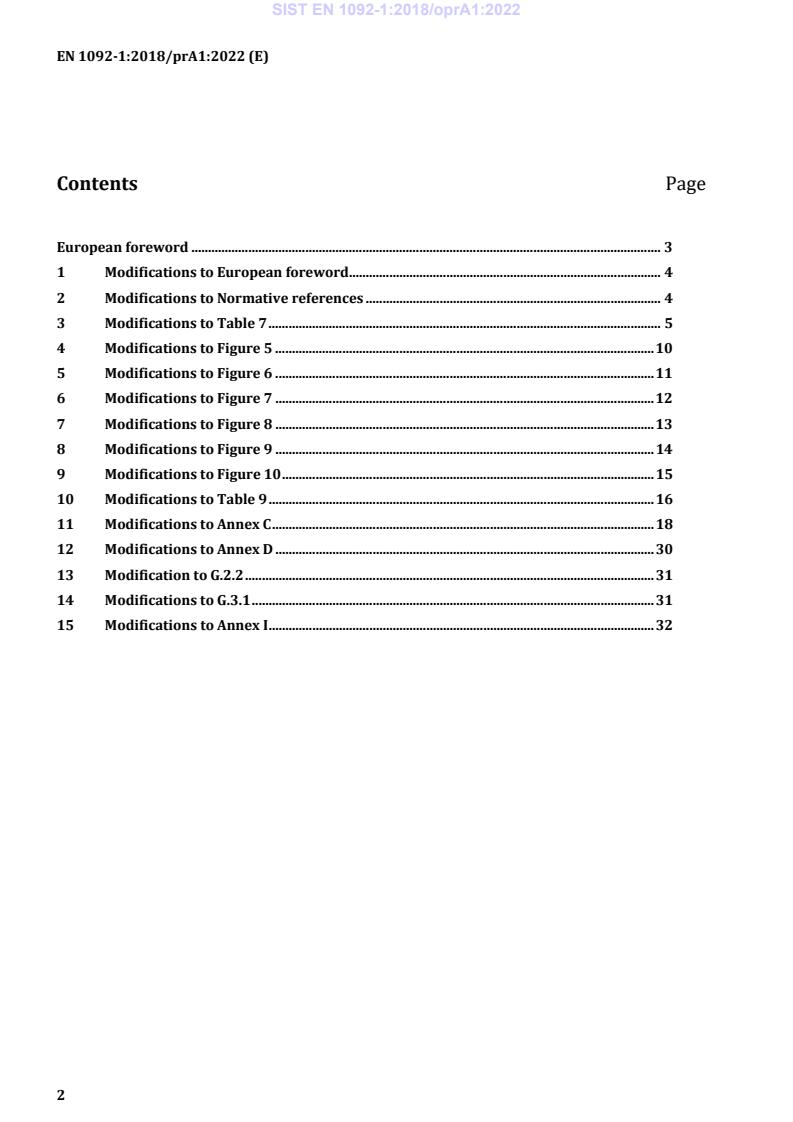
Contents Page
European foreword . 3
1 Modifications to European foreword . 4
2 Modifications to Normative references . 4
3 Modifications to Table 7 . 5
4 Modifications to Figure 5 . 10
5 Modifications to Figure 6 . 11
6 Modifications to Figure 7 . 12
7 Modifications to Figure 8 . 13
8 Modifications to Figure 9 . 14
9 Modifications to Figure 10 . 15
10 Modifications to Table 9 . 16
11 Modifications to Annex C . 18
12 Modifications to Annex D . 30
13 Modification to G.2.2 . 31
14 Modifications to G.3.1 . 31
15 Modifications to Annex I . 32
SIST EN 1092-1:2018/oprA1:2022
EN 1092-1:2018/prA1:2022 (E)
European foreword
This document (EN 1092-1:2018/prA1:2022) has been prepared by Technical Committee CEN/TC 74
“Flanges and their joints”, the secretariat of which is held by DIN.
This document is currently submitted to the CEN Enquiry.
In comparison with the previous edition, the following technical modifications have been made:
— Editorial modifications
— Modification and update the clause “Normative references”
— Modifications to Table 7 “Synoptic table”
— Modifications on some figures
— Modifications to Annex C “Masses of flanges”
— Modifications to Annex D “Table D.1”
— Modifications to Annex G “G.3.1 General”
— Modifications to Annex I “Table I.3”
This document has been prepared under a mandate given to CEN by the European Commission and the
European Free Trade Association, and supports essential requirements of EU Directive(s).
For relationship with EU Directive(s), see informative Annex ZA, which is an integral part of
EN 1092-1:2018.
SIST EN 1092-1:2018/oprA1:2022
EN 1092-1:2018/prA1:2022 (E)
1 Modifications to European foreword
Change d) to the following:
“d) flanges Type 05 for PN 160 to PN 400 were implemented.”
2 Modifications to Normative references
Add the following:
EN 10222-4:2017+A1, Steel forgings for pressure purposes - Part 4: Weldable fine grain steels with high
proof strength
EN 10216-2:2013+A1:2019, Seamless steel tubes for pressure purposes - Technical delivery conditions -
Part 2: Non-alloy and alloy steel tubes with specified elevated temperature properties
EN 10216-5:2021, Seamless steel tubes for pressure purposes - Technical delivery conditions - Part 5:
Stainless steel tubes
EN 10217-3:2019, Welded steel tubes for pressure purposes - Technical delivery conditions - Part 3: Electric
welded and submerged arc welded alloy fine grain steel tubes with specified room, elevated and low
temperature properties
EN 10217-7:2021, Welded steel tubes for pressure purposes - Technical delivery conditions - Part 7:
Stainless steel tubes
EN 13445-3:2021, Unfired pressure vessels - Part 3: Design
EN ISO 3452-1:2021, Non-destructive testing - Penetrant testing - Part 1: General principles (ISO 3452-
1:2021)
EN ISO 6892-1:2019, Metallic materials - Tensile testing - Part 1: Method of test at room temperature (ISO
6892-1:2019)
EN ISO 11666:2018, Non-destructive testing of welds - Ultrasonic testing - Acceptance levels (ISO
11666:2018)
EN ISO 17640:2018, Non-destructive testing of welds - Ultrasonic testing - Techniques, testing levels, and
assessment (ISO 17640:2018)
SIST EN 1092-1:2018/oprA1:2022
EN 1092-1:2018/prA1:2022 (E)
3 Modifications to Table 7
Replace Table 7:
Table 7 — Synoptic table
DN
Flange type or collar type
PN
dimensions identical with PN 6 X
2,5
6 X X X X X X X X X X X X X X X X X X X X X X X X X X X X X
dimensions identical with dimensions identical with
10 X X X X X X X X X X X X X
PN 40 PN 16
dimensions identical with
16 X X X X X X X X X X X X X X X X X
PN 40
a) Type 01
25 dimensions identical with PN 40 X X X X X X X X X X
40 X X X X X X X X X X X X X X X X X
dimensions identical with
63 X X X X X X X X X X X
PN 100
100 X X X X X X X X X X X X X X X X
2,5 dimensions identical with PN 6
6 X X X X X X X X X X X X X X X X X X X X
dimensions identical with dimensions identical with
10 X X X X X X X X
PN 40 PN 16
dimensions identical with
16 X X X X X X X X X X X X X X
PN 40
b) Types 02 and 32
25 dimensions identical with PN 40 X X X X X X X X
40 X X X X X X X X X X X X X X X X X X X X
2,5 dimensions identical with PN 6
6 X X X X X X X X X X X X X X X X X X X X X X X X X
dimensions identical with dimensions identical with
10 X X X X X X X X X X X X X
PN 40 PN 16
1 000
1 200
1 400
1 600
1 800
2 000
2 200
2 400
2 600
2 800
3 000
3 200
3 400
3 600
3 800
4 000
SIST EN 1092-1:2018/oprA1:2022
EN 1092-1:2018/prA1:2022 (E)
DN
Flange type or collar type
PN
dimensions identical with
16 X X X X X X X X X X X X X X X X X
X
PN 40
25 dimensions identical with PN 40 X X X X X X X X X X X
40 X X X X X X X X X X X X X X X X X
c) Types 02 and 35
2,5 dimensions identical with PN 6
6 X X X X X X X X X X X X X X X X X X X
10 dimensions identical with PN 16 X X X X X
16 X X X X X X X X X X X X X X X X X
d) Type 02 and 36
dimensions
dimensions identical with PN 16 identical with
2,5
PN 10
dimensions
6 dimensions identical with PN 16 identical with
PN 10
e) Type 02 and 33/37
10 dimensions identical with PN 16 X X X
16 X X X X X X X X X X X X X
dimensions identical with dimensions identical with
10 X X X X X X X X
PN 40 PN 16
dimensions identical with
16 X X X X X X X X X X X X X X
PN 40
25 dimensions identical with PN 40 X X X X X X X X
f) Type 04 and 34
40 X X X X X X X X X X X X X X X X X
1 000
1 200
1 400
1 600
1 800
2 000
2 200
2 400
2 600
2 800
3 000
3 200
3 400
3 600
3 800
4 000
SIST EN 1092-1:2018/oprA1:2022
EN 1092-1:2018/prA1:2022 (E)
DN
Flange type or collar type
PN
2,5 dimensions identical with PN 6 X
6 X X X X X X X X X X X X X X X X X X X X X X X X X X X X X
dimensions identical with dimensions identical with
10 X X X X X X X X X X X X X
PN 40 PN 16
dimensions identical with
16 X X X X X X X X X X X X X X X X X X
PN 40
25 dimensions identical with PN 40 X X X X X X X X
40 X X X X X X X X X X X X X X X X X X X X
63 Use PN 100 X X X X X X X X X X X
100 X X X X X X X X X X X X X X X X
160 X X X X X X X X X X X X X
g) Type 05
250 X X X X X X X X X X X
320 X X X X X X X X X X X X
400 X X X X X X X X X X X
2,5 dimensions identical with PN 6 X X X X X X X X X X X X X X X X X
6 X X X X X X X X X X X X X X X X X X X X X X X X X X X X X X X X X X X X X
dimensions identical with dimensions identical with
10 X X X X X X X X X X X X X X X X X X X X X X
PN 40 PN 16
h) Type 11
dimensions identical with
16 X X X X X X X X X X X X X X X X X X X X X X
X
PN 40
dimensions identical with PN 10
1 000
1 200
1 400
1 600
1 800
2 000
2 200
2 400
2 600
2 800
3 000
3 200
3 400
3 600
3 800
4 000
SIST EN 1092-1:2018/oprA1:2022
EN 1092-1:2018/prA1:2022 (E)
DN
Flange type or collar type
PN
25 dimensions identical with PN 40 X X X X X X X X X X X X
40 X X X X X X X X X X X X X X X X X X X X
dimensions identical with
63 X X X X X X X X X X X
PN 100
100 X X X X X X X X X X X X X X X X
160 X X X X X X X X X X X X X
250 X X X X X X X X X X X
320 X X X X X X X X X X X X
400 X X X X X X X X X X X
6 X X X X X X X X X X X X X X X
dimensions identical with dimensions identical with
10 X X X X X X X X
PN 40 PN 16
dimensions identical with
16 X X X X X X X X X X X X X X X X X X
PN 40
25 dimensions identical with PN 40 X X X X X X X X
i) Type 12
40 X X X X X X X X X X X X X X X X X X X X
dimensions identical with
63 X X X X X X
PN 100
100 X X X X X X X X X X X X
dimensions identical with PN 10
1 000
1 200
1 400
1 600
1 800
2 000
2 200
2 400
2 600
2 800
3 000
3 200
3 400
3 600
3 800
4 000
SIST EN 1092-1:2018/oprA1:2022
EN 1092-1:2018/prA1:2022 (E)
DN
Flange type or collar type
PN
6 X X X X X X X X X X X X
dimensions identical with dimensions identical with
PN 40 PN 16
dimensions identical with
16 X X X X X X
PN 40
25 dimensions identical with PN 40
j) Type 13
40 X X X X X X X X X X X X
dimensions identical with
63 X X X X X X
PN 100
100 X X X X X X X X X X X X
2,5 X X X X X X X X X X X X X X X X X X X X X X X X
6 X X X X X X X X X X X X X X X X X X X X X X X X X X X X X
dimensions identical with dimensions identical with
10 X X X X X X X X X X X X X X X X X
PN 40 PN 16
dimensions identical with
16 X X X X X X X X X X X X X X X X X X X X X X X
PN 40
25 dimensions identical with PN 40 X X X X X X X X X X X X
40 X X X X X X X X X X X X X X X X X X X X
dimensions identical with
63 X X X X X X X X X X X
k) Type 21
PN 100
100 X X X X X X X X X X X X X X X X
160 X X X X X X X X X X X X X
250 X X X X X X X X X X X X X
320 X X X X X X X X X X X X
400 X X X X X X X X X X X
1 000
1 200
1 400
1 600
1 800
2 000
2 200
2 400
2 600
2 800
3 000
3 200
3 400
3 600
3 800
4 000
SIST EN 1092-1:2018/oprA1:2022
EN 1092-1:2018/prA1:2022 (E)
4 Modifications to Figure 5
Replace Figure 5:
a) b) Type 01 c)Type 05 d) Type 11 e) Type 02 and 35 f) Type 02 and 36 g) Type 02 and 37
This diagram illustrates the
arrangement but not necessarily the
correct number of bolt holes.
Refer to the column “Bolting
Number” in Table 10 for the actual
number.
h) Type 21
NOTE 1 Dimension N1 is measured at the intersection of the hub draft angle and the back face of the flange.
NOTE 2 For dimension Gmax, refer to NOTE 1 of 5.6.1.
Figure 5 — Dimensions of PN 2,5 flanges
SIST EN 1092-1:2018/oprA1:2022
EN 1092-1:2018/prA1:2022 (E)
5 Modifications to Figure 6
Replace Figure 6:
a) b) Type 01 c) Type 02 and 32 d) Type 02 and 33 e) Type 02 and 35 f) Type 02 and 36 g) Type 02 and 37
This diagram illustrates the
arrangement but not necessarily the
correct number of bolt holes.
Refer to the column “Bolting Number”
in Table 11 for the actual number.
h) Type 05 i) Type 11 j) Type 12 k) Type 13 l) Type 21
NOTE 1 Dimensions N1, N2 and N3 are measured at the intersection of the hub draft angle and the back face of the flange.
NOTE 2 For dimension d1, see Table 8.
NOTE 3 For dimensions G refer to NOTE 1 of 5.6.1.
max
NOTE 4 Type 33; lapped pipe end without determination of thickness and height.
Figure 6 — Dimensions of PN 6 flanges
SIST EN 1092-1:2018/oprA1:2022
EN 1092-1:2018/prA1:2022 (E)
6 Modifications to Figure 7
Replace Figure 7:
a) b) Type 01 c) Type 02 and 32 d) Type 02 and 33 e) Type 02 and 35 f) Type 02 and 36 g) Type 02 and 37
This diagram illustrates the
arrangement but not
necessarily the correct number
of bolt holes.
Refer to the column “Bolting
Number” in Table 12 for the
actual number.
h) Type 04 and 34 i) Type 05 j) Type 11 k) Type 12 l) Type 13 m) Type 21
NOTE 1 Dimensions N , N and N are measured at the intersection of the hub draft angle and the back face of the flange.
1 2 3
NOTE 2 For dimension d1, see Table 8.
NOTE 3 For dimensions Gmax refer to NOTE 1 of 5.6.1.
NOTE 4 Type 33; lapped pipe end without determination of thickness and height.
Figure 7 — Dimensions of PN 10 flanges
---------------------- Page
...