


IEC 62820-1-2:2026
(Main)Building intercom systems - Part 1-2: System requirements - Building intercom systems using the Internet protocol (IP)
General Information
- Abstract
IEC 62820‑1‑2:2026 specifies the technical requirements for the composition, functions, performance and test methods of building intercom systems using the Internet protocol (IP), and it is a supplement to IEC 62820‑1‑1. This document is applicable to the IP building intercom systems for both residential and commercial buildings.
- Status
- Published
- Publication Date
- 26-Jul-2026
- Technical Committee
- TC 79 - Alarm and electronic security systems
- Drafting Committee
- WG 13 - TC 79/WG 13
- Current Stage
- PPUB - Publication issued
- Start Date
- 27-Jul-2026
- Completion Date
- 15-Jul-2026
Buy Documents
REDLINE IEC 62820-1-2:2026 RLV - Building intercom systems - Part 1-2: System requirements - Building intercom systems using the Internet protocol (IP)
iec62820-1-2{ed2.0}en - Building intercom systems - Part 1-2: System requirements - Building intercom systems using the Internet protocol (IP)

iec62820-1-2{ed2.0}fr - <p>Systemes d'interphone de bâtiment - Partie 1-2: Exigences du systeme - Systemes d'interphone de bâtiment utilisant le protocole internet (IP)</p>
Overview
IEC 62820-1-2:2026 is an international standard that defines system requirements for building intercom systems using Internet Protocol (IP). Developed by the International Electrotechnical Commission (IEC), this standard provides comprehensive technical requirements covering the composition, functionality, performance, and testing methods for IP-based intercom systems installed in both residential and commercial buildings. It serves as a supplement to IEC 62820-1-1 and addresses the specific needs and challenges of implementing IP communications for modern building intercom solutions.
Key Topics
- System Composition: Defines the structural components needed for IP building intercom systems, ensuring interoperability and reliable communication between devices.
- Functional Requirements: Covers both basic and enhanced functionalities such as bidirectional audio/video communication, messaging features, and remote configuration capabilities.
- Performance Criteria: Establishes benchmarks for audio and video quality, including loudness, echo adaptation, latency, switching times, image resolution, refresh rates, and synchronization between audio and video streams.
- Security Provisions: Specifies controls for network access and data integrity to protect against unauthorized access and ensure the confidentiality and reliability of transmitted information.
- Testing Methods: Outlines laboratory conditions and methodologies, including objective and subjective evaluations of audio/video performance and security features, to certify compliance with the standard.
Applications
The adoption of IEC 62820-1-2:2026 is essential for:
- Residential Buildings: Facilitating secure and reliable door communication, visitor identification, and access management for apartments, condominiums, and gated communities.
- Commercial Properties: Supporting communication and security in offices, schools, hospitals, hotels, and public buildings by integrating with broader security and building management systems.
- Remote Management: Enabling advanced functions such as offsite device monitoring, configuration, firmware updates, and secure video/image storage.
- System Integration: Ensuring compatibility between intercom devices, including audio and video units, call panels, and security management units across IP networks.
- Quality Assurance: Providing a framework for manufacturers and service providers to assess and validate the operational quality and security of their IP-based building intercom products.
Related Standards
For a holistic approach to building intercom system deployment and compliance, the following standards are closely related to IEC 62820-1-2:
- IEC 62820-1-1: Building intercom systems - System requirements - General requirements.
- IEC 62820-2: Building intercom systems - Requirements for advanced security building intercom systems (ASBIS).
- IEC 62820-3-1 and 3-2: Application guidelines, including general guidance and advanced security applications.
- ITU-T P.501: Test signals for use in telephony and other speech-based applications, referenced for audio testing.
- ISO/IEC Terminology Databases: For an up-to-date understanding of terms and definitions used in standardization, consult IEC Electropedia and the ISO Online Browsing Platform.
Practical Value
Complying with IEC 62820-1-2:2026 ensures interoperability, security, functionality, and high performance in IP building intercom systems. This benefits system integrators, manufacturers, facility managers, and end-users by:
- Increasing building security and communication reliability.
- Facilitating easier upgrades and integration with modern building networks.
- Supporting regulatory compliance and international market access for intercom products.
- Enabling future-proofed installations adaptable to technological advancements in network infrastructure and IoT devices.
By leveraging the guidelines and test methodologies defined in this standard, stakeholders can guarantee that their IP-based intercom solutions meet rigorous international quality benchmarks and respond effectively to the evolving needs of smart buildings and digital communication environments.
Relations
- Effective Date
- 05-Sep-2023
Buy Documents
REDLINE IEC 62820-1-2:2026 RLV - Building intercom systems - Part 1-2: System requirements - Building intercom systems using the Internet protocol (IP)
iec62820-1-2{ed2.0}en - Building intercom systems - Part 1-2: System requirements - Building intercom systems using the Internet protocol (IP)
iec62820-1-2{ed2.0}fr - <p>Systemes d'interphone de bâtiment - Partie 1-2: Exigences du systeme - Systemes d'interphone de bâtiment utilisant le protocole internet (IP)</p>
Get Certified
Connect with accredited certification bodies for this standard

CIS Institut d.o.o.
Personal Protective Equipment (PPE) certification body. Notified Body NB-2890 for EU Regulation 2016/425 PPE.

Kiwa BDA Testing
Building and construction product certification.
Kmetijski inštitut Slovenije
Agricultural Institute of Slovenia. Soil testing, plant health, agricultural product analysis.
Sponsored listings
Frequently Asked Questions
IEC 62820-1-2:2026 is a standard published by the International Electrotechnical Commission (IEC). Its full title is "Building intercom systems - Part 1-2: System requirements - Building intercom systems using the Internet protocol (IP)". This standard covers: IEC 62820‑1‑2:2026 specifies the technical requirements for the composition, functions, performance and test methods of building intercom systems using the Internet protocol (IP), and it is a supplement to IEC 62820‑1‑1. This document is applicable to the IP building intercom systems for both residential and commercial buildings.
IEC 62820‑1‑2:2026 specifies the technical requirements for the composition, functions, performance and test methods of building intercom systems using the Internet protocol (IP), and it is a supplement to IEC 62820‑1‑1. This document is applicable to the IP building intercom systems for both residential and commercial buildings.
IEC 62820-1-2:2026 is classified under the following ICS (International Classification for Standards) categories: 13.320 - Alarm and warning systems. The ICS classification helps identify the subject area and facilitates finding related standards.
IEC 62820-1-2:2026 has the following relationships with other standards: It is inter standard links to IEC 62820-1-2:2017. Understanding these relationships helps ensure you are using the most current and applicable version of the standard.
IEC 62820-1-2:2026 is available in PDF format for immediate download after purchase. The document can be added to your cart and obtained through the secure checkout process. Digital delivery ensures instant access to the complete standard document.
Standards Content (Sample)
IEC 62820-1-2 ®
Edition 2.0 2026-07
INTERNATIONAL
STANDARD
REDLINE VERSION
Building intercom systems -
Part 1-2: System requirements - Building intercom systems using the Internet
protocol (IP)
ICS 13.320 ISBN 978-2-8327-1419-5
All rights reserved. Unless otherwise specified, no part of this publication may be reproduced or utilized in any form or
by any means, electronic or mechanical, including photocopying and microfilm, without permission in writing from either
IEC or IEC's member National Committee in the country of the requester. If you have any questions about IEC copyright
or have an enquiry about obtaining additional rights to this publication, please contact the address below or your local
IEC member National Committee for further information.
IEC Secretariat Tel.: +41 22 919 02 11
3, rue de Varembé info@iec.ch
CH-1211 Geneva 20 www.iec.ch
Switzerland
About the IEC
The International Electrotechnical Commission (IEC) is the leading global organization that prepares and publishes
International Standards for all electrical, electronic and related technologies.
About IEC publications
The technical content of IEC publications is kept under constant review by the IEC. Please make sure that you have the
latest edition, a corrigendum or an amendment might have been published.
IEC publications search - IEC Products & Services Portal - products.iec.ch
webstore.iec.ch/advsearchform Discover our powerful search engine and read freely all the
The advanced search enables to find IEC publications by a publications previews, graphical symbols and the glossary.
variety of criteria (reference number, text, technical With a subscription you will always have access to up to date
committee, …). It also gives information on projects, content tailored to your needs.
replaced and withdrawn publications.
Electropedia - www.electropedia.org
The world's leading online dictionary on electrotechnology,
IEC Just Published - webstore.iec.ch/justpublished
Stay up to date on all new IEC publications. Just Published containing more than 22 500 terminological entries in English
details all new publications released. Available online and and French, with equivalent terms in 25 additional languages.
once a month by email. Also known as the International Electrotechnical Vocabulary
(IEV) online.
IEC Customer Service Centre - webstore.iec.ch/csc
If you wish to give us your feedback on this publication or
need further assistance, please contact the Customer
Service Centre: sales@iec.ch.
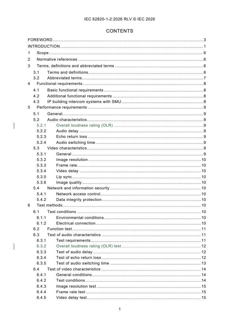
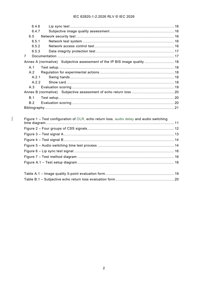
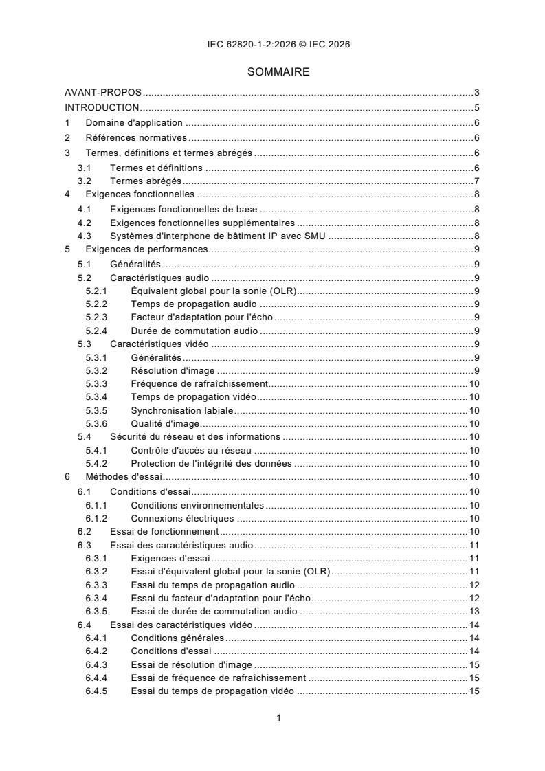
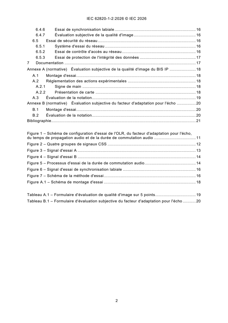
CONTENTS
FOREWORD . 3
INTRODUCTION . 1
1 Scope . 6
2 Normative references . 6
3 Terms, definitions and abbreviated terms . 6
3.1 Terms and definitions. 6
3.2 Abbreviated terms . 7
4 Functional requirements . 8
4.1 Basic functional requirements . 8
4.2 Additional functional requirements . 8
4.3 IP building intercom systems with SMU . 8
5 Performance requirements . 9
5.1 General . 9
5.2 Audio characteristics . 9
5.2.1 Overall loudness rating (OLR) . 9
5.2.2 Audio delay . 9
5.2.3 Echo return loss . 9
5.2.4 Audio switching time . 9
5.3 Video characteristics . 9
5.3.1 General . 9
5.3.2 Image resolution . 10
5.3.3 Frame rate . 10
5.3.4 Video delay . 10
5.3.5 Lip sync . 10
5.3.6 Image quality . 10
5.4 Network and information security . 10
5.4.1 Network access control . 10
5.4.2 Data integrity protection . 10
6 Test methods . 10
6.1 Test conditions . 10
6.1.1 Environmental conditions . 10
6.1.2 Electrical connection. 10
6.2 Function test . 11
6.3 Test of audio characteristics . 11
6.3.1 Test requirements . 11
6.3.2 Overall loudness rating (OLR) test . 12
6.3.3 Test of audio delay . 12
6.3.4 Test of echo return loss . 12
6.3.5 Test of audio switching time . 13
6.4 Test of video characteristics . 14
6.4.1 General conditions . 14
6.4.2 Test conditions . 14
6.4.3 Image resolution test . 15
6.4.4 Frame rate test . 15
6.4.5 Video delay test . 15
6.4.6 Lip sync test . 16
6.4.7 Subjective image quality assessment . 16
6.5 Network security test . 16
6.5.1 Network test system . 16
6.5.2 Network access control test . 16
6.5.3 Data integrity protection test . 17
7 Documentation . 17
Annex A (normative) Subjective assessment of the IP BIS image quality . 18
A.1 Test setup . 18
A.2 Regulation for experimental actions . 18
A.2.1 Swing hands . 18
A.2.2 Show card . 18
A.3 Evaluation scoring . 19
Annex B (normative) Subjective assessment of echo return loss . 20
B.1 Test setup . 20
B.2 Evaluation scoring . 20
Bibliography . 21
Figure 1 – Test configuration of OLR, echo return loss, audio delay and audio switching
time diagram . 11
Figure 2 – Four groups of CSS signals. 12
Figure 3 – Test signal A . 13
Figure 4 – Test signal B . 14
Figure 5 – Audio switching time test process . 14
Figure 6 – Lip sync test signal . 16
Figure 7 – Test method diagram . 16
Figure A.1 – Test setup diagram . 18
Table A.1 – Image quality 5-point evaluation form . 19
Table B.1 – Subjective echo return loss evaluation form . 20
INTERNATIONAL ELECTROTECHNICAL COMMISSION
____________
Building intercom systems -
Part 1-2: System requirements -
Building intercom systems using the Internet protocol (IP)
FOREWORD
1) The International Electrotechnical Commission (IEC) is a worldwide organization for standardization comprising all
national electrotechnical committees (IEC National Committees). The object of IEC is to promote international co-
operation on all questions concerning standardization in the electrical and electronic fields. To this end and in addition
to other activities, IEC publishes International Standards, Technical Specifications, Technical Reports, Publicly
Available Specifications (PAS) and Guides (hereafter referred to as "IEC Publication(s)"). Their preparation is
entrusted to technical committees; any IEC National Committee interested in the subject dealt with may participate
in this preparatory work. International, governmental and non-governmental organizations liaising with the IEC also
participate in this preparation. IEC collaborates closely with the International Organization for Standardization (ISO)
in accordance with conditions determined by agreement between the two organizations.
2) The formal decisions or agreements of IEC on technical matters express, as nearly as possible, an international
consensus of opinion on the relevant subjects since each technical committee has representation from all interested
IEC National Committees.
3) IEC Publications have the form of recommendations for international use and are accepted by IEC National
Committees in that sense. While all reasonable efforts are made to ensure that the technical content of IEC
Publications is accurate, IEC cannot be held responsible for the way in which they are used or for any
misinterpretation by any end user.
4) In order to promote international uniformity, IEC National Committees undertake to apply IEC Publications
transparently to the maximum extent possible in their national and regional publications. Any divergence between
any IEC Publication and the corresponding national or regional publication shall be clearly indicated in the latter.
5) IEC itself does not provide any attestation of conformity. Independent certification bodies provide conformity
assessment services and, in some areas, access to IEC marks of conformity. IEC is not responsible for any services
carried out by independent certification bodies.
6) All users should ensure that they have the latest edition of this publication.
7) No liability shall attach to IEC or its directors, employees, servants or agents including individual experts and
members of its technical committees and IEC National Committees for any personal injury, property damage or other
damage of any nature whatsoever, whether direct or indirect, or for costs (including legal fees) and expenses arising
out of the publication, use of, or reliance upon, this IEC Publication or any other IEC Publications.
8) Attention is drawn to the Normative references cited in this publication. Use of the referenced publications is
indispensable for the correct application of this publication.
9) IEC draws attention to the possibility that the implementation of this document may involve the use of (a) patent(s).
IEC takes no position concerning the evidence, validity or applicability of any claimed patent rights in respect thereof.
As of the date of publication of this document, IEC had received notice of a patent, which may be required to
implement this document. However, implementers are cautioned that this may not represent the latest information,
which may be obtained from the patent database available at https://patents.iec.ch. IEC shall not be held responsible
for identifying any or all such patent rights.
This redline version of the official IEC Standard allows the user to identify the changes made to
the previous edition IEC 62820-1-2:2017. A vertical bar appears in the margin wherever a change
has been made. Additions are in green text, deletions are in strikethrough red text.
IEC 62820-1-2 has been prepared by IEC technical committee 79: Alarm and electronic security
systems. It is an International Standard.
This second edition cancels and replaces the first edition published in 2017. This edition
constitutes a technical revision.
This edition includes the following significant technical changes with respect to the previous edition:
a) addition of the requirement for overall loudness rating (OLR) when the screen size of the hands-
free intercom unit is larger than 10 inches at the test distance of 30 cm;
b) addition of the requirement for test conditions when the test distance is 30 cm or longer;
c) addition of the method of testing overall loudness rating (OLR) when the screen size of the
hands-free intercom unit is larger than 10 inches.
The text of this International Standard is based on the following documents:
Draft Report on voting
79/721/CDV 79/729A/RVC
Full information on the voting for its approval can be found in the report on voting indicated in the
above table.
The language used for the development of this International Standard is English.
This document was drafted in accordance with ISO/IEC Directives, Part 2, and developed in
accordance with ISO/IEC Directives, Part 1 and ISO/IEC Directives, IEC Supplement, available at
www.iec.ch/members_experts/refdocs. The main document types developed by IEC are described
in greater detail at www.iec.ch/publications.
A list of all parts in the IEC 62820 series, published under the general title Building intercom
systems, can be found on the IEC website.
The committee has decided that the contents of this document will remain unchanged until the
stability date indicated on the IEC website under webstore.iec.ch in the data related to the specific
document. At this date, the document will be
– reconfirmed,
– withdrawn, or
– revised.
INTRODUCTION
The IEC 62820 series of standards set out the technical requirements for the composition,
functions, performance, and test methods of building intercom systems for building entry and
application guidelines and consist of five parts:
Part 1-1: System requirements - General
Part 1-2: System requirements - Building intercom systems using the internet protocol (IP)
Part 2: Requirements for advanced security building intercom systems (ASBIS)
Part 3-1: Application guidelines - General
Part 3-2: Application guidelines - Advanced security building intercom systems (ASBIS)
1 Scope
IEC 62820-1-2 specifies the technical requirements for the composition, functions, performance
and test methods of building intercom systems using the Internet protocol (IP), and it is a
supplement to IEC 62820-1-1.
This document is applicable to the IP building intercom systems for both residential and
commercial buildings.
NOTE A BIS that has a mixture of IP and non-IP connections is not covered by IEC 62820-1-2 but covered by
IEC 62820-1-1.
2 Normative references
The following documents are referred to in the text in such a way that some or all of their content
constitutes requirements of this document. For dated references, only the edition cited applies.
For undated references, the latest edition of the referenced document (including any amendments)
applies.
IEC 62820-1-1:20162026, Building intercom systems - Part 1-1: System requirements - General
ITU-T P.501, Test signals for use in telephonometry telephony and other speech-based
applications
3 Terms, definitions and abbreviated terms
3.1 Terms and definitions
For the purposes of this document, the terms and definitions given in IEC 62820-1-1 and the
following apply.
ISO and IEC maintain terminology databases for use in standardization at the following addresses:
– IEC Electropedia: available at https://www.electropedia.org/
– ISO Online browsing platform: available at https://www.iso.org/obp
3.1.1
audio delay
audio latency
one way delay (OWD) time of the transmitted audio signal from the microphone of one intercom
unit through other components in the system to the loudspeaker of other intercom unit
3.1.2
audio switching time
time, from one transmission direction to the other, measured from the removal of the signal in the
first direction until the level in the second direction reaches 3 dB below its final value
3.1.3
echo return loss
ability of the local intercom unit to avoid retransmitting the audio signal received from the far
intercom unit back again to it
3.1.4
intercom unit
device that is able to establish an audio connection or an audio and video connection between
each other (SMU, VCU and URU) and is specifically designed to be a component of a BIS
Note 1 to entry: Devices which can be connected to IP transmission network such as smartphones or tablets are not
considered as intercom units.
3.1.5
Internet protocol
IP
network layer-3 protocol in the OSI model containing addressing and control information to enable
data packets to be routed in a network and primary network layer protocol in the TCP/IP protocol
suite according to IETF RFC 791 and IETF RFC 2460 and any subsequent evolution
3.1.6
IP transmission network
communication network used to achieve the relevant functions of IP BIS, such as data transmission
and control
3.1.7
lip sync
temporal relationship between transmitted audio signal and video signal
Note 1 to entry: Lip sync value is used to demonstrate the relationship between audio and video signal synchronization.
3.1.8
single talk
type of non simultaneous 2 way speech in which two parties communicate by alternating speech
spurts without interrupting each other
3.1.9
double talk
type of non simultaneous 2 way speech in which two parties communicate by alternating speech
spurts in which both parties may can interrupt each other
3.1.10
subjective image quality assessment
method where people, as observers, evaluate the image quality
Note 1 to entry: Test environment, observer and evaluation method shall comply with certain standards, in the same
way the methodology for the subjective assessment of the quality of the television pictures adopted ITU-R BT.500-13
(01/2012).
3.1.11
video delay
one way delay (OWD) time of the transmitted video signal from the camera of one intercom unit
through other components to the display on the other intercom unit
3.2 Abbreviated terms
ACR absolute category rating
BIS building intercom system
CSS composite source signal
DCR degradation category rating
EUT equipment under test
FPS frames per second
FR frame rate
IP Internet protocol
LED light-emitting diode
LIG LED image generator
LRGP loudness rating guard-ring position
MRP mouth reference point
OLR overall loudness rating
OSI open systems interconnection
OWD one way delay
PSG programmable signal generator
QoS quality of service
SMU security management unit
TVL television lines
URU user receiver unit
VCD video capture device
VCU visitor call unit
VRD video receiver device
4 Functional requirements
4.1 Basic functional requirements
Basic functional requirements of IP BIS shall comply with the requirements specified in
IEC 62820-1-1:20162026, 4.1.
4.2 Additional functional requirements
In addition to the additional functional requirements specified in IEC 62820-1-1:20162026, 4.2, an
IP building intercom system may can comply with the following requirements:
a) Intercom unit to intercom unit speech
URU may can be able to make addressing calls to other URU and conduct two-way speech.
b) Voice message function
IP building intercom system may can allow the caller to leave voice messages from the VCU.
c) Intercom unit to intercom unit video and speech
URU may can be able to conduct two-way video and audio communication with other URU.
d) Video and voice messages function
IP building intercom system may can allow the caller to leave video and voice messages from
the VCU.
4.3 IP building intercom systems with SMU
In addition to the functional requirements specified in 4.1 and 4.2, IP building intercom systems
with SMU may can comply with the following requirements:
a) Automatic detection of device status
The SMU may can detect the status of other devices in the system.
b) Remote configuration and update
The SMU may can remotely configure the operating mode of the devices and update the
firmware and software of the devices.
c) Image storing and replaying function
When the URU with video function is communicating with an SMU equipped with a camera, it
may can be able to store and replay the images captured by the SMU.
5 Performance requirements
5.1 General
The performance requirements of IP BIS shall comply with the requirements specified in
IEC 62820-1-1:20162026, Clause 5.
The following requirements shall be fulfilled when the intercom devices are linked in a local network,
wired or wireless. In case some devices are linked through a public network (i.e. Internet), where
it is not possible to guarantee QoS, the requirements do not apply.
5.2 Audio characteristics
5.2.1 Overall loudness rating (OLR)
When the screen size of the hands-free unit is greater than 10 inches, the test distance can be
adjusted to 30 cm. In this case, the overall loudness rating (OLR) shall comply with the following
requirements:
+10
a) at the VCU: 25 dB;
−5
+10
b) at the hands-free URU and hands-free SMU: 28 dB.
−5
NOTE This document does not limit the maximum size of the intercom terminal screen. In theory, the user can choose
30 cm test distance according to the size of the screen, but this document only gives the OLR value based on 30 cm
test.
5.2.2 Audio delay
Audio delay between two intercom units shall not be more than 300 ms.
5.2.3 Echo return loss
This requirement may can be evaluated in two ways.
a) Objective evaluation
Hands-free units: the echo return loss shall not be less than 45 dB.
Handset unit: the echo return loss shall not be less than 46 dB.
NOTE Non-simultaneous systems are evaluated by subjective test.
b) Subjective evaluation
The subjective evaluation of echo return loss shall be not less than 3 points.
5.2.4 Audio switching time
The audio switching time shall not be more than 200 ms.
NOTE This requirement does not apply to simultaneous talk and single talk BIS.
5.3 Video characteristics
5.3.1 General
Video characteristics of IP BIS shall comply with the requirements specified in
IEC 62820-1-1:20162026, 5.2.2 to 5.2.5 and the following.
5.3.2 Image resolution
Image resolution (measured at the centre of the image) of IP BIS shall not be less than 130 TVL
for the visible area smaller than 4,0 inches (10,16 cm), not be less than 240 TVL for the visible
area equal or larger than 4,0 inches (10,16 cm) and smaller than 7,0 inches (17,78 cm), and not
be less than 320 TVL for the visible area of 7,0 inches (17,78 cm) or larger.
5.3.3 Frame rate
Frame rate of digital video signals shall not be less than 15 FPS.
5.3.4 Video delay
The unit-to-unit Video delay between two intercom units shall not be more than 300 ms.
5.3.5 Lip sync
Relative time difference of video and audio signal concurrent transmission should be between –
185 ms and +90 ms.
NOTE This only applies to audio-video systems and not to audio only systems.
5.3.6 Image quality
Images shall not present obvious phenomenon such as image blur, mosaic effect or image fracture.
The average subjective image quality assessment shall not be less than 3 points.
5.4 Network and information security
5.4.1 Network access control
When a user or device accesses the network of IP BIS or manages the system, the system shall
identify the user or device, determine if access is granted as well as the access right. Identification
ways can vary, measures other than identification may can be used provided that they protect the
system from unauthorized access.
5.4.2 Data integrity protection
The IP BIS may can detect the integrity of the users' alarm and unlocking control data. It also may
can offer protection for the integrity of the users' data by encryption or other ways.
6 Test methods
6.1 Test conditions
6.1.1 Environmental conditions
Temperature: 15 ºC to 35 ºC.
Relative humidity: 25 % to 75 %.
Atmospheric pressure: 86 kPa to 106 kPa.
6.1.2 Electrical connection
The EUT shall be connected according to the manufacturer's recommendations for the basic
configuration of the test. The EUT configuration should shall meet the requirements to realize the
system functions.
6.2 Function test
The EUT shall be operated according to the product instruction manual. The functions of the
system shall be checked item by item and shall comply with the requirements specified in Clause
4.
6.3 Test of audio characteristics
6.3.1 Test requirements
Unless otherwise stated, test conditions shall comply with the requirements as specified in
IEC 62820-1-1:20162026, Clause A.1, and the additional below requirements:
a) The CSS signal defined by ITU-T P.501 shall be adopted. It is recommended to use 48 kHz
sampling rate sequence of pseudo random noise. Every CSS signal consists of 248,62 ms
excitation signal and 101,38 ms pause. The average sound pressure generated by the test
signal in MRP should be –4,7 dB Pa.
b) When testing the echo return loss and audio switching time, it is required to measure the audio
transmission at both ends. The centre of both the artificial mouth and the standard half-inch
(1,27 cm) free field microphone shall point towards the centre of the EUT with 16° deviated
from the central axis of the EUT as shown in Figure 1. In case of handset unit, the supporting
panel shall be replaced by fixing the artificial mouth and standard half-inch (1,27 cm) free field
microphone at the LRGP.
c) When the 30 cm test distance is adopted, the centre of the lip ring of the artificial mouth and
the centre of the standard half-inch free-field microphone shall be placed 30 cm right in front
of the central axis of the EUT enclosure surface, and all audio characteristic tests shall be
carried out in an anechoic chamber environment.
NOTE This document does not limit the maximum size of the intercom unit screen. In theory, the user can choose the
30 cm test distance according to the size of the screen, but this document only gives the test method based on 10 cm
or 30 cm test.
Dimensions in metres
R can be 10 cm or 30 cm. When the screen size of the EUT is greater than 10 inches, R shall be 30 cm, and when the
screen size of the EUT is less than or equal to 10 inches, R shall be 10 cm. Please note that the R on both sides should
be consistent during each test.
Figure 1 – Test configuration of OLR, echo return loss, audio delay and audio switching
time diagram
6.3.2 Overall loudness rating (OLR) test
If the screen size of the EUT is no more than 10 inches, the OLR test method is carried out in
accordance with the test method set forth in IEC 62820-1-1:2026, Annex A. If the screen size of
the hands-free intercom unit is greater than 10 inches, the overall loudness rating (OLR) test
method set forth in IEC 62820-1-1:2026, Annex A, should be carried out, but the centre of the lip
ring of the artificial mouth and the standard half-inch free field microphone shall be in a place
30 cm right in front of the centre of the enclosure surface of the hands-free EUT and as shown in
Figure 1. The test result should meet the requirements of 5.2.1.
6.3.3 Test of audio delay
The test signal consists of four groups of CSS signals (see Figure 2). The first three groups of
CSS signals are used for training, which makes the channel stable. The continuous excitation
signal of the fourth CSS signal is used for audio delay measuring.
The audio signal generator shall generate the CSS test signal through the artificial mouth to initiate
the audio in the local terminal. Use an audio analyser to compare the time difference between the
fourth pulse of the test signal and the test signal transmitted through the BIS from terminal to
terminal. The time difference is the audio delay.
The test should consist of 10 measurements. Each time the communication should be reconnected.
The average value of 10 measurements is the audio delay result. The test result should meet the
requirements of 5.2.2.
Figure 2 – Four groups of CSS signals
6.3.4 Test of echo return loss
6.3.4.1 Objective test of echo return loss
a) The test environmental noise shall not exceed 30 dB(A). It is recommended to conduct the test
in a full-anechoic chamber or semi-anechoic chamber. If the EUT has the volume control, it
shall be set to the maximum level before the Larsen effect appears. The CSS test signal
illustrated in Figure 2 shall be used. During the test, the communication of the EUT shall not
be interrupted.
b) The total time of two-way point-to-point audio delays, T, shall be tested separately and recorded
according to 6.3.3. If the total time of the two-way transmission of the EUT is less than 100 ms,
there is no need to do this test.
c) The audio signal generator shall generate the CSS test signal through the artificial mouth to
initiate audio in the local terminal. The test signal is transmitted from the local unit to the remote
unit. When the test signal returns back, it is measured by the microphone at the local unit after
a delay T.
d) Use an acoustic measurement analyser in 1/3 octave frequency interval to measure and record
the ear bearing pressure Pi of the last 100 ms from the fourth CSS signal group within 200 Hz
to 4 000 Hz. The echo return loss at the remote unit shall be calculated by differentials between
sound pressure of the MRP at the sending unit and the voice signal average sound pressure
from the remote unit, using the following formula:
Echo loss=−4,7− 20lg Pi
∑
i=4
where
i is the serial number of frequency. The corresponding central frequency shall comply with
IEC 62820-1-1:20162026, Table A.1;
Pi is the average sound pressure on the frequency bandwidth.
e) Based on the test method mentioned in c) to d), repeat the test measurement for 10 times
continuously and take the average as the test result shall meet the requirements of 5.2.3.
NOTE The suggested interval between two measurements is over 1,5 s.
6.3.4.2 Subjective evaluation of echo return loss
The subjective evaluation of echo return loss shall comply with Annex B.
6.3.5 Test of audio switching time
a) This test shall use two groups of test signals A and B. The test signal A shall use 10 continuous
CSS signals, where the duration shall be longer than the expected time that the single direction
transmission of BIS can become stable (see Figure 3). Test signal B shall consists of four CSS
signals, the first pulse of the CSS signal is used for measurement (see Figure 4).
b) Figure 5 shows the audio switching time progress. Separately measure the audio time delay
from one terminal to the other in both directions based on the test method specified in 6.3.3.
c) The audio signal generator shall generate test signal A through the artificial mouth to initiate
the audio transmission in the local terminal and record the initial time. When the remote
th
terminal finishes playing the 10 CSS pulse the MRP of the remote terminal shall generate the
test signal B.
d) Use microphone in the local terminal to record the output signal coming from the remote
terminal and measure the time, T , from the start of the first CSS signal B until it reaches
DS
3 dB below the average normal audio transmission amplitude. The audio switching time T is
S
calculated by the difference between T and T . The test result shall meet the requirements
DS D2
of 5.2.4.
Figure 3 – Test signal A
Figure 4 – Test signal B
Key
T Delay time of testing signal from local terminal to remote terminal
D1
T Delay time of testing signal from remote terminal to local terminal
D2
T Audio switching time
s
Figure 5 – Audio switching time test process
6.4 Test of video characteristics
6.4.1 General conditions
Test conditions of 5.3 specified in this document shall conform to the requirements as specified in
Clause B.1 of IEC 62820-1-1:20162026, and the test conditions of 6.4.3 to 6.4.6 should conform
to 6.4.2.
6.4.2 Test conditions
Unless stated, environmental noise at the test site shall not exceed 40 dB(A).
Video characteristic tests should use a LED image generator (LIG) as test signal resource.
The LED image generator (LIG) consists of 10 × 10 LEDs matrix and a programmable signal
generator (PSG). The LED matrix is used to generate stroboscopic images. The PSG will control
the LED matrix to generate the appropriate pattern; a single LED as a basic unit is activated every
time and it shall be able to roll horizontally and then vertically. The LIG test unit shall be equipped
with two falling edge synchronous outputs interface. In order to avoid that audio signal affects the
video test, it is suggested that LIG is able to control two identical LED matrixes simultaneously.
LED matrix A is placed in front of the VCD camera as the test signal source; LED matrix B is placed
close to the VRD where a digital video camera can capture pictures of both the VRD display and
LED matrix B.
By adjusting the distance between the LED matrix and VCD, the LED matrix image shall fill out the
display on VRD for both vertical and horizontal axis and stay focused.
Additionally, a digital video camera shall be used with adjustable frame rate and support external
synchronize signal input function.
6.4.3 Image resolution test
Test methods specified in IEC 62820-1-1:20162026, Clause B.3 shall be followed. The test results
shall comply with the requirements set forth in 5.3.2.
6.4.4 Frame rate test
a) The test signal shall be generated by continuously activating the 10 horizontal LEDs at the
centre of the LIG device.
b) Adjust the frequency of the LIG (f) from 1 Hz (each led is activated once every second with a
flash time of 1/ (10f) s) upward so the 10 LEDs will light up one by one horizontally according
to the frequency set. Watch the image on the VRD and stop increasing the frequency of the
LIG when the LEDs appear to stop moving on the VRD. This state shall be maintained over
10 s without any drop to ensure its validity.
c) Record the value of frequency on the LIG. This value is the frame rate (fr). The test result shall
conform to the requirements set forth in 5.3.3.
6.4.5 Video delay test
a) This test should be carried out after 6.4.4, using the frame rate (fr) of EUT as the frequency f
of LIG. Use the continuously changing image generated by the LIG on the 10 × 10 LED matrixes
as the test signal.
b) The tested VCD shall capture the image generated by LIG A. At the receiver end, a digital
video camera shall continuously capture image frames, with a frame rate fr during 3 s, of the
received video image on the VRD display together with the image generated by LIG B.
c) For each captured image frame within the 3 s, compare the location of active LED on the LIG
B and on the VRD display in the same frame and count the number of the LEDs (n) difference
between them. Video delay of this picture is (1 000 × n) / fr (ms).
d) Filter the values discarding the 10 % of higher values. The resulting highest value is the video
delay. The test result shall conform to the requirements set forth in 5.3.4.
NOTE If the BIS is able to mute audio or reduce audio volume to avoid Larsen effect, the test can be conducted with
only one LED matrix, locating it in front of the VCD and beside the VRD. It will represent LIG A or B indistinctly in the
test description.
6.4.6 Lip sync test
The test condition and method should meet the requirements of both 6.3.3 and 6.4.5.
The audio signal generator plays ten groups of test signals, each one with four CSS pulses
(Figure 6), and each group separated by a pause of 400 ± 0,1 ms, with a total test signal length of
16 586,2 ms. The first three CSS signals in each group are used for training; the fourth will be
used to measure the audio delay (as described in 6.3.3) and also to trigger, in the falling edge, the
digital video camera to capture one image simultaneously. Therefore, a measurement of audio
delay and video delay are taken at the end of every group test signal, i.e. 10 measurements in
total.
Calculate the video delay according to the video delay method (6.4.5).
Calculate the audio delay according to the audio delay method (6.3.3).
Pair the audio and video delay measurements that are synchronously captured and calculate:
Lip sync = video delay – audio delay
A positive value means that audio is advanced with respect to video.
Filter the values of lip sync measurements discarding the highest and lowest values. The rest of
the values shall conform to the requirements set forth in 5.3.5.
Figure 6 – Lip sync test signal
6.4.7 Subjective image quality assessment
Subjective image quality assessment shall be carried out as described in Annex A.
6.5 Network security test
6.5.1 Network test system
The network test system is shown in Figure 7.
Figure 7 – Test method diagram
6.5.2 Network access control test
Identification should be prior to when users access the IP BIS. The system only offers functional
operation for authorized users. The test result should satisfy the requirements as specified in 5.4.1.
6.5.3 Data integrity protection test
Adopt a network protocol analyser software (such as a software packet sniffer) to capture
communicating data packets. It will be checked whether the IP BIS is equipped with measures
such as encryption, digital signature and Hash function to detect the integrity of the users data
storage and the alarm and unlocking control data. The test result should satisfy the requirements
as specified in 5.4.2.
7 Documentation
The documentation of the IP BIS shall comply with the requirements specified in
IEC 62820-1-1:20162026, Clause 7.
Annex A
(normative)
Subjective assessment of the IP BIS image quality
A.1 Test setup
The test can be arranged as shown in Figure A.1. Specified methods are as follows:
Figure A.1 – Test setup diagram
a) The tested system can consist of the VCU, URU, SMU and IP transmission network.
b) There shall be at least one laboratory person taking part in the test. The number of scoring
persons shall not be less than three skilled persons.
c) The laboratory person shall look at the camera of the VCD horizontally, with a suitable distance
between 30 cm and 50 cm.
d) The scoring person shall look at the display of the VRD horizontally, with a suitable distance.
e) The test actions as ruled by the laboratory person include at least the following: greetings, self-
introduction, show identity cards and thank you. The above operation will be repeated at least
three times.
f) Scoring values are introduced individually and grading personnel observe and rate image
quality on the basis of Table A.1 under the five-grade marking system.
A.2 Regulation for experimental actions
A.2.1 Swing hands
The experimenter shall swing the hand about 2 times/s.
A.2.2 Show card
The experimenter shall put the name card or ID card in front of the VCD camera as closely as
possible and the image transferred to the VRD shall show the card on the screen covering as much
area as possible without losing focus and keep it standstill f
...
IEC 62820-1-2 ®
Edition 2.0 2026-07
INTERNATIONAL
STANDARD
Building intercom systems -
Part 1-2: System requirements - Building intercom systems using the Internet
protocol (IP)
ICS 13.320 ISBN 978-2-8327-1305-1
All rights reserved. Unless otherwise specified, no part of this publication may be reproduced or utilized in any form or
by any means, electronic or mechanical, including photocopying and microfilm, without permission in writing from either
IEC or IEC's member National Committee in the country of the requester. If you have any questions about IEC copyright
or have an enquiry about obtaining additional rights to this publication, please contact the address below or your local
IEC member National Committee for further information.
IEC Secretariat Tel.: +41 22 919 02 11
3, rue de Varembé info@iec.ch
CH-1211 Geneva 20 www.iec.ch
Switzerland
About the IEC
The International Electrotechnical Commission (IEC) is the leading global organization that prepares and publishes
International Standards for all electrical, electronic and related technologies.
About IEC publications
The technical content of IEC publications is kept under constant review by the IEC. Please make sure that you have the
latest edition, a corrigendum or an amendment might have been published.
IEC publications search - IEC Products & Services Portal - products.iec.ch
webstore.iec.ch/advsearchform Discover our powerful search engine and read freely all the
The advanced search enables to find IEC publications by a publications previews, graphical symbols and the glossary.
variety of criteria (reference number, text, technical With a subscription you will always have access to up to date
committee, …). It also gives information on projects, content tailored to your needs.
replaced and withdrawn publications.
Electropedia - www.electropedia.org
The world's leading online dictionary on electrotechnology,
IEC Just Published - webstore.iec.ch/justpublished
Stay up to date on all new IEC publications. Just Published containing more than 22 500 terminological entries in English
details all new publications released. Available online and and French, with equivalent terms in 25 additional languages.
once a month by email. Also known as the International Electrotechnical Vocabulary
(IEV) online.
IEC Customer Service Centre - webstore.iec.ch/csc
If you wish to give us your feedback on this publication or
need further assistance, please contact the Customer
Service Centre: sales@iec.ch.
CONTENTS
FOREWORD . 3
INTRODUCTION . 5
1 Scope . 6
2 Normative references . 6
3 Terms, definitions and abbreviated terms . 6
3.1 Terms and definitions. 6
3.2 Abbreviated terms . 7
4 Functional requirements . 8
4.1 Basic functional requirements . 8
4.2 Additional functional requirements . 8
4.3 IP building intercom systems with SMU . 8
5 Performance requirements . 9
5.1 General . 9
5.2 Audio characteristics . 9
5.2.1 Overall loudness rating (OLR) . 9
5.2.2 Audio delay . 9
5.2.3 Echo return loss . 9
5.2.4 Audio switching time . 9
5.3 Video characteristics . 9
5.3.1 General . 9
5.3.2 Image resolution . 10
5.3.3 Frame rate . 10
5.3.4 Video delay . 10
5.3.5 Lip sync . 10
5.3.6 Image quality . 10
5.4 Network and information security . 10
5.4.1 Network access control . 10
5.4.2 Data integrity protection . 10
6 Test methods . 10
6.1 Test conditions . 10
6.1.1 Environmental conditions . 10
6.1.2 Electrical connection. 10
6.2 Function test . 11
6.3 Test of audio characteristics . 11
6.3.1 Test requirements . 11
6.3.2 Overall loudness rating (OLR) test . 12
6.3.3 Test of audio delay . 12
6.3.4 Test of echo return loss . 12
6.3.5 Test of audio switching time . 13
6.4 Test of video characteristics . 14
6.4.1 General conditions . 14
6.4.2 Test conditions . 14
6.4.3 Image resolution test . 15
6.4.4 Frame rate test . 15
6.4.5 Video delay test . 15
6.4.6 Lip sync test . 16
6.4.7 Subjective image quality assessment . 16
6.5 Network security test . 16
6.5.1 Network test system . 16
6.5.2 Network access control test . 16
6.5.3 Data integrity protection test . 17
7 Documentation . 17
Annex A (normative) Subjective assessment of the IP BIS image quality . 18
A.1 Test setup . 18
A.2 Regulation for experimental actions . 18
A.2.1 Swing hands . 18
A.2.2 Show card . 18
A.3 Evaluation scoring . 19
Annex B (normative) Subjective assessment of echo return loss . 20
B.1 Test setup . 20
B.2 Evaluation scoring . 20
Bibliography . 21
Figure 1 – Test configuration of OLR, echo return loss, audio delay and audio switching
time diagram . 11
Figure 2 – Four groups of CSS signals. 12
Figure 3 – Test signal A . 13
Figure 4 – Test signal B . 14
Figure 5 – Audio switching time test process . 14
Figure 6 – Lip sync test signal . 16
Figure 7 – Test method diagram . 16
Figure A.1 – Test setup diagram . 18
Table A.1 – Image quality 5-point evaluation form . 19
Table B.1 – Subjective echo return loss evaluation form . 20
INTERNATIONAL ELECTROTECHNICAL COMMISSION
____________
Building intercom systems -
Part 1-2: System requirements -
Building intercom systems using the Internet protocol (IP)
FOREWORD
1) The International Electrotechnical Commission (IEC) is a worldwide organization for standardization comprising all
national electrotechnical committees (IEC National Committees). The object of IEC is to promote international co-
operation on all questions concerning standardization in the electrical and electronic fields. To this end and in addition
to other activities, IEC publishes International Standards, Technical Specifications, Technical Reports, Publicly
Available Specifications (PAS) and Guides (hereafter referred to as "IEC Publication(s)"). Their preparation is
entrusted to technical committees; any IEC National Committee interested in the subject dealt with may participate
in this preparatory work. International, governmental and non-governmental organizations liaising with the IEC also
participate in this preparation. IEC collaborates closely with the International Organization for Standardization (ISO)
in accordance with conditions determined by agreement between the two organizations.
2) The formal decisions or agreements of IEC on technical matters express, as nearly as possible, an international
consensus of opinion on the relevant subjects since each technical committee has representation from all interested
IEC National Committees.
3) IEC Publications have the form of recommendations for international use and are accepted by IEC National
Committees in that sense. While all reasonable efforts are made to ensure that the technical content of IEC
Publications is accurate, IEC cannot be held responsible for the way in which they are used or for any
misinterpretation by any end user.
4) In order to promote international uniformity, IEC National Committees undertake to apply IEC Publications
transparently to the maximum extent possible in their national and regional publications. Any divergence between
any IEC Publication and the corresponding national or regional publication shall be clearly indicated in the latter.
5) IEC itself does not provide any attestation of conformity. Independent certification bodies provide conformity
assessment services and, in some areas, access to IEC marks of conformity. IEC is not responsible for any services
carried out by independent certification bodies.
6) All users should ensure that they have the latest edition of this publication.
7) No liability shall attach to IEC or its directors, employees, servants or agents including individual experts and
members of its technical committees and IEC National Committees for any personal injury, property damage or other
damage of any nature whatsoever, whether direct or indirect, or for costs (including legal fees) and expenses arising
out of the publication, use of, or reliance upon, this IEC Publication or any other IEC Publications.
8) Attention is drawn to the Normative references cited in this publication. Use of the referenced publications is
indispensable for the correct application of this publication.
9) IEC draws attention to the possibility that the implementation of this document may involve the use of (a) patent(s).
IEC takes no position concerning the evidence, validity or applicability of any claimed patent rights in respect thereof.
As of the date of publication of this document, IEC had received notice of a patent, which may be required to
implement this document. However, implementers are cautioned that this may not represent the latest information,
which may be obtained from the patent database available at https://patents.iec.ch. IEC shall not be held responsible
for identifying any or all such patent rights.
IEC 62820-1-2 has been prepared by IEC technical committee 79: Alarm and electronic security
systems. It is an International Standard.
This second edition cancels and replaces the first edition published in 2017. This edition
constitutes a technical revision.
This edition includes the following significant technical changes with respect to the previous edition:
a) addition of the requirement for overall loudness rating (OLR) when the screen size of the hands-
free intercom unit is larger than 10 inches at the test distance of 30 cm;
b) addition of the requirement for test conditions when the test distance is 30 cm or longer;
c) addition of the method of testing overall loudness rating (OLR) when the screen size of the
hands-free intercom unit is larger than 10 inches.
The text of this International Standard is based on the following documents:
Draft Report on voting
79/721/CDV 79/729A/RVC
Full information on the voting for its approval can be found in the report on voting indicated in the
above table.
The language used for the development of this International Standard is English.
This document was drafted in accordance with ISO/IEC Directives, Part 2, and developed in
accordance with ISO/IEC Directives, Part 1 and ISO/IEC Directives, IEC Supplement, available at
www.iec.ch/members_experts/refdocs. The main document types developed by IEC are described
in greater detail at www.iec.ch/publications.
A list of all parts in the IEC 62820 series, published under the general title Building intercom
systems, can be found on the IEC website.
The committee has decided that the contents of this document will remain unchanged until the
stability date indicated on the IEC website under webstore.iec.ch in the data related to the specific
document. At this date, the document will be
– reconfirmed,
– withdrawn, or
– revised.
INTRODUCTION
The IEC 62820 series of standards set out the technical requirements for the composition,
functions, performance, and test methods of building intercom systems for building entry and
application guidelines and consist of five parts:
Part 1-1: System requirements - General
Part 1-2: System requirements - Building intercom systems using the internet protocol (IP)
Part 2: Requirements for advanced security building intercom systems (ASBIS)
Part 3-1: Application guidelines - General
Part 3-2: Application guidelines - Advanced security building intercom systems (ASBIS)
1 Scope
IEC 62820-1-2 specifies the technical requirements for the composition, functions, performance
and test methods of building intercom systems using the Internet protocol (IP), and it is a
supplement to IEC 62820-1-1.
This document is applicable to the IP building intercom systems for both residential and
commercial buildings.
NOTE A BIS that has a mixture of IP and non-IP connections is not covered by IEC 62820-1-2 but covered by
IEC 62820-1-1.
2 Normative references
The following documents are referred to in the text in such a way that some or all of their content
constitutes requirements of this document. For dated references, only the edition cited applies.
For undated references, the latest edition of the referenced document (including any amendments)
applies.
IEC 62820-1-1:2026, Building intercom systems - Part 1-1: System requirements - General
ITU-T P.501, Test signals for use in telephony and other speech-based applications
3 Terms, definitions and abbreviated terms
3.1 Terms and definitions
For the purposes of this document, the terms and definitions given in IEC 62820-1-1 and the
following apply.
ISO and IEC maintain terminology databases for use in standardization at the following addresses:
– IEC Electropedia: available at https://www.electropedia.org/
– ISO Online browsing platform: available at https://www.iso.org/obp
3.1.1
audio delay
audio latency
one way delay (OWD) time of the transmitted audio signal from the microphone of one intercom
unit through other components in the system to the loudspeaker of other intercom unit
3.1.2
audio switching time
time, from one transmission direction to the other, measured from the removal of the signal in the
first direction until the level in the second direction reaches 3 dB below its final value
3.1.3
echo return loss
ability of the local intercom unit to avoid retransmitting the audio signal received from the far
intercom unit back again to it
3.1.4
intercom unit
device that is able to establish an audio connection or an audio and video connection between
each other (SMU, VCU and URU) and is specifically designed to be a component of a BIS
Note 1 to entry: Devices which can be connected to IP transmission network such as smartphones or tablets are not
considered as intercom units.
3.1.5
Internet protocol
IP
network layer-3 protocol in the OSI model containing addressing and control information to enable
data packets to be routed in a network and primary network layer protocol in the TCP/IP protocol
suite according to IETF RFC 791 and IETF RFC 2460 and any subsequent evolution
3.1.6
IP transmission network
communication network used to achieve the relevant functions of IP BIS, such as data transmission
and control
3.1.7
lip sync
temporal relationship between transmitted audio signal and video signal
Note 1 to entry: Lip sync value is used to demonstrate the relationship between audio and video signal synchronization.
3.1.8
single talk
type of non simultaneous 2 way speech in which two parties communicate by alternating speech
spurts without interrupting each other
3.1.9
double talk
type of non simultaneous 2 way speech in which two parties communicate by alternating speech
spurts in which both parties can interrupt each other
3.1.10
subjective image quality assessment
method where people, as observers, evaluate the image quality
Note 1 to entry: Test environment, observer and evaluation method shall comply with certain standards, in the same
way the methodology for the subjective assessment of the quality of the television pictures adopted ITU-R BT.500-13
(01/2012).
3.1.11
video delay
one way delay (OWD) time of the transmitted video signal from the camera of one intercom unit
through other components to the display on the other intercom unit
3.2 Abbreviated terms
ACR absolute category rating
BIS building intercom system
CSS composite source signal
DCR degradation category rating
EUT equipment under test
FPS frames per second
IP Internet protocol
LED light-emitting diode
LIG LED image generator
LRGP loudness rating guard-ring position
MRP mouth reference point
OLR overall loudness rating
OSI open systems interconnection
OWD one way delay
PSG programmable signal generator
QoS quality of service
SMU security management unit
TVL television lines
URU user receiver unit
VCD video capture device
VCU visitor call unit
VRD video receiver device
4 Functional requirements
4.1 Basic functional requirements
Basic functional requirements of IP BIS shall comply with the requirements specified in
IEC 62820-1-1:2026, 4.1.
4.2 Additional functional requirements
In addition to the additional functional requirements specified in IEC 62820-1-1:2026, 4.2, an IP
building intercom system can comply with the following requirements:
a) Intercom unit to intercom unit speech
URU can be able to make addressing calls to other URU and conduct two-way speech.
b) Voice message function
IP building intercom system can allow the caller to leave voice messages from the VCU.
c) Intercom unit to intercom unit video and speech
URU can be able to conduct two-way video and audio communication with other URU.
d) Video and voice messages function
IP building intercom system can allow the caller to leave video and
...
IEC 62820-1-2 ®
Edition 2.0 2026-07
NORME
INTERNATIONALE
Systèmes d'interphone de bâtiment -
Partie 1-2: Exigences du système - Systèmes d'interphone de bâtiment utilisant
le protocole internet (IP)
ICS 13.320 ISBN 978-2-8327-1305-1
Droits de reproduction réservés. Sauf indication contraire, aucune partie de cette publication ne peut être reproduite ni
utilisée sous quelque forme que ce soit et par aucun procédé, électronique ou mécanique, y compris la photocopie et
les microfilms, sans l'accord écrit de l'IEC ou du Comité national de l'IEC du pays du demandeur. Si vous avez des
questions sur le copyright de l'IEC ou si vous désirez obtenir des droits supplémentaires sur cette publication, utilisez
les coordonnées ci-après ou contactez le Comité national de l'IEC de votre pays de résidence.
IEC Secretariat Tel.: +41 22 919 02 11
3, rue de Varembé info@iec.ch
CH-1211 Geneva 20 www.iec.ch
Switzerland
A propos de l'IEC
La Commission Electrotechnique Internationale (IEC) est la première organisation mondiale qui élabore et publie des
Normes internationales pour tout ce qui a trait à l'électricité, à l'électronique et aux technologies apparentées.
A propos des publications IEC
Le contenu technique des publications IEC est constamment revu. Veuillez vous assurer que vous possédez l’édition la
plus récente, un corrigendum ou amendement peut avoir été publié.
Recherche de publications IEC - IEC Products & Services Portal - products.iec.ch
webstore.iec.ch/advsearchform Découvrez notre puissant moteur de recherche et consultez
La recherche avancée permet de trouver des publications gratuitement tous les aperçus des publications, symboles
IEC en utilisant différents critères (numéro de référence, graphiques et le glossaire. Avec un abonnement, vous aurez
texte, comité d’études, …). Elle donne aussi des toujours accès à un contenu à jour adapté à vos besoins.
informations sur les projets et les publications remplacées
ou retirées. Electropedia - www.electropedia.org
Le premier dictionnaire d'électrotechnologie en ligne au
IEC Just Published - webstore.iec.ch/justpublished monde, avec plus de 22 500 articles terminologiques en
Restez informé sur les nouvelles publications IEC. Just anglais et en français, ainsi que les termes équivalents
dans 25 langues additionnelles. Egalement appelé
Published détaille les nouvelles publications parues.
Disponible en ligne et une fois par mois par email. Vocabulaire Electrotechnique International (IEV) en ligne.
Service Clients - webstore.iec.ch/csc
Si vous désirez nous donner des commentaires sur cette
publication ou si vous avez des questions contactez-
nous: sales@iec.ch.
SOMMAIRE
AVANT-PROPOS . 3
INTRODUCTION . 5
1 Domaine d'application . 6
2 Références normatives . 6
3 Termes, définitions et termes abrégés . 6
3.1 Termes et définitions . 6
3.2 Termes abrégés . 7
4 Exigences fonctionnelles . 8
4.1 Exigences fonctionnelles de base . 8
4.2 Exigences fonctionnelles supplémentaires . 8
4.3 Systèmes d'interphone de bâtiment IP avec SMU . 8
5 Exigences de performances . 9
5.1 Généralités . 9
5.2 Caractéristiques audio . 9
5.2.1 Équivalent global pour la sonie (OLR) . 9
5.2.2 Temps de propagation audio . 9
5.2.3 Facteur d'adaptation pour l'écho . 9
5.2.4 Durée de commutation audio . 9
5.3 Caractéristiques vidéo . 9
5.3.1 Généralités . 9
5.3.2 Résolution d'image . 9
5.3.3 Fréquence de rafraîchissement. 10
5.3.4 Temps de propagation vidéo . 10
5.3.5 Synchronisation labiale . 10
5.3.6 Qualité d'image. 10
5.4 Sécurité du réseau et des informations . 10
5.4.1 Contrôle d'accès au réseau . 10
5.4.2 Protection de l'intégrité des données . 10
6 Méthodes d'essai . 10
6.1 Conditions d'essai . 10
6.1.1 Conditions environnementales . 10
6.1.2 Connexions électriques . 10
6.2 Essai de fonctionnement . 10
6.3 Essai des caractéristiques audio . 11
6.3.1 Exigences d'essai . 11
6.3.2 Essai d'équivalent global pour la sonie (OLR) . 11
6.3.3 Essai du temps de propagation audio . 12
6.3.4 Essai du facteur d'adaptation pour l'écho . 12
6.3.5 Essai de durée de commutation audio . 13
6.4 Essai des caractéristiques vidéo . 14
6.4.1 Conditions générales . 14
6.4.2 Conditions d'essai . 14
6.4.3 Essai de résolution d'image . 15
6.4.4 Essai de fréquence de rafraîchissement . 15
6.4.5 Essai du temps de propagation vidéo . 15
6.4.6 Essai de synchronisation labiale . 16
6.4.7 Évaluation subjective de la qualité d'image . 16
6.5 Essai de sécurité du réseau . 16
6.5.1 Système d'essai du réseau . 16
6.5.2 Essai de contrôle d'accès au réseau . 16
6.5.3 Essai de protection de l'intégrité des données . 17
7 Documentation . 17
Annexe A (normative) Évaluation subjective de la qualité d'image du BIS IP . 18
A.1 Montage d'essai . 18
A.2 Réglementation des actions expérimentales . 18
A.2.1 Signe de main . 18
A.2.2 Présentation de carte . 18
A.3 Évaluation de la notation . 19
Annexe B (normative) Évaluation subjective du facteur d'adaptation pour l'écho . 20
B.1 Montage d'essai . 20
B.2 Évaluation de la notation . 20
Bibliographie . 21
Figure 1 – Schéma de configuration d'essai de l'OLR, du facteur d'adaptation pour l'écho,
du temps de propagation audio et de la durée de commutation audio . 11
Figure 2 – Quatre groupes de signaux CSS . 12
Figure 3 – Signal d'essai A . 13
Figure 4 – Signal d'essai B . 14
Figure 5 – Processus d'essai de la durée de commutation audio . 14
Figure 6 – Signal d'essai de synchronisation labiale . 16
Figure 7 – Schéma de la méthode d'essai . 16
Figure A.1 – Schéma de montage d'essai . 18
Tableau A.1 – Formulaire d'évaluation de qualité d'image sur 5 points . 19
Tableau B.1 – Formulaire d'évaluation subjective du facteur d'adaptation pour l'écho . 20
Annexe ACOMMISSION ÉLECTROTECHNIQUE INTERNATIONALE
____________
Systèmes d'interphone de bâtiment -
Partie 1-2: Exigences du système -
Systèmes d'interphone de bâtiment utilisant le protocole Internet (IP)
AVANT-PROPOS
1) La Commission Électrotechnique Internationale (IEC) est une organisation mondiale de normalisation composée de
l'ensemble des comités électrotechniques nationaux (Comités nationaux de l'IEC). L'IEC a pour objet de favoriser la
coopération internationale pour toutes les questions de normalisation dans les domaines de l'électricité et de
l'électronique. À cet effet, l'IEC – entre autres activités – publie des Normes internationales, des Spécifications
techniques, des Rapports techniques, des Spécifications accessibles au public (PAS) et des Guides (ci-après
dénommés "Publication(s) de l'IEC"). Leur élaboration est confiée à des comités d'études, aux travaux desquels tout
Comité national intéressé par le sujet traité peut participer. Les organisations internationales, gouvernementales et
non gouvernementales, en liaison avec l'IEC, participent également aux travaux. L'IEC collabore étroitement avec
l'Organisation Internationale de Normalisation (ISO), selon des conditions fixées par accord entre les deux
organisations.
2) Les décisions ou accords officiels de l'IEC concernant les questions techniques représentent, dans la mesure du
possible, un accord international sur les sujets étudiés, étant donné que les Comités nationaux de l'IEC intéressés
sont représentés dans chaque comité d'études.
3) Les Publications de l'IEC se présentent sous la forme de recommandations internationales et sont agréées comme
telles par les Comités nationaux de l'IEC. Tous les efforts raisonnables sont entrepris afin que l'IEC s'assure de
l'exactitude du contenu technique de ses publications; l'IEC ne peut pas être tenue responsable de l'éventuelle
mauvaise utilisation ou interprétation qui en est faite par un quelconque utilisateur final.
4) Dans le but d'encourager l'uniformité internationale, les Comités nationaux de l'IEC s'engagent, dans toute la mesure
possible, à appliquer de façon transparente les Publications de l'IEC dans leurs publications nationales et régionales.
Toutes divergences entre toutes Publications de l'IEC et toutes publications nationales ou régionales
correspondantes doivent être indiquées en termes clairs dans ces dernières.
5) L'IEC elle-même ne fournit aucune attestation de conformité. Des organismes de certification indépendants
fournissent des services d'évaluation de conformité et, dans certains secteurs, accèdent aux marques de conformité
de l'IEC. L'IEC n'est responsable d'aucun des services effectués par les organismes de certification indépendants.
6) Tous les utilisateurs doivent s'assurer qu'ils sont en possession de la dernière édition de cette publication.
7) Aucune responsabilité ne doit être imputée à l'IEC, à ses administrateurs, employés, auxiliaires ou mandataires, y
compris ses experts particuliers et les membres de ses comités d'études et des Comités nationaux de l'IEC, pour
tout préjudice causé en cas de dommages corporels et matériels, ou de tout autre dommage de quelque nature que
ce soit, directe ou indirecte, ou pour supporter les coûts (y compris les frais de justice) et les dépenses découlant
de la publication ou de l'utilisation de cette Publication de l'IEC ou de toute autre Publication de l'IEC, ou au crédit
qui lui est accordé.
8) L'attention est attirée sur les références normatives citées dans cette publication. L'utilisation de publications
référencées est obligatoire pour une application correcte de la présente publication.
9) L'IEC attire l'attention sur le fait que la mise en application du présent document peut entraîner l'utilisation d'un ou
de plusieurs brevets. L'IEC ne prend pas position quant à la preuve, à la validité et à l'applicabilité de tout droit de
brevet revendiqué à cet égard. À la date de publication du présent document, l'IEC n'a pas reçu notification qu'un
ou plusieurs brevets pouvaient être nécessaires à sa mise en application. Toutefois, il y a lieu d'avertir les
responsables de la mise en application du présent document que des informations plus récentes sont susceptibles
de figurer dans la base de données de brevets, disponible à l'adresse https://patents.iec.ch. L'IEC ne saurait être
tenue pour responsable de ne pas avoir identifié de tels droits de brevets.
L'IEC 62820-1-2 a été établie par le comité d'études 79 de l'IEC: Systèmes d'alarme et de sécurité
électroniques. Il s'agit d'une Norme internationale.
Cette deuxième édition annule et remplace la première édition parue en 2017. Cette édition
constitue une révision technique.
Cette édition inclut les modifications techniques significatives suivantes par rapport à l'édition
précédente:
a) ajout de l'exigence d'équivalent global pour la sonie (OLR) lorsque la taille de l'écran de l'unité
d'interphone mains libres est supérieure à 10 pouces à la distance d'essai de 30 cm;
b) ajout de l'exigence pour les conditions d'essai lorsque la distance d'essai est d'une longueur
supérieure ou égale à 30 cm;
c) ajout d'une méthode pour réaliser les essais d'équivalent global pour la sonie (OLR) lorsque
la taille de l'écran de l'unité d'interphone mains libres est supérieure à 10 pouces.
Le texte de cette Norme internationale est issu des documents suivants:
Projet Rapport de vote
79/721/CDV 79/729A/RVC
Le rapport de vote indiqué dans le tableau ci-dessus donne toute information sur le vote ayant
abouti à son approbation.
La langue employée pour l'élaboration de cette Norme internationale est l'anglais.
Ce document a été rédigé selon les Directives ISO/IEC, Partie 2, il a été développé selon les
Directives ISO/IEC, Partie 1 et les Directives ISO/IEC, Supplément IEC, disponibles sous
www.iec.ch/members_experts/refdocs. Les principaux types de documents développés par l'IEC
sont décrits plus en détail sous www.iec.ch/publications.
Une liste de toutes les parties de la série IEC 62820, publiées sous le titre général Systèmes
d'interphone de bâtiment, se trouve sur le site web de l'IEC.
Le comité a décidé que le contenu de ce document ne sera pas modifié avant la date de stabilité
indiquée sur le site web de l'IEC sous webstore.iec.ch dans les données relatives au document
recherché. À cette date, le document sera:
– reconduit,
– supprimé, ou
– révisé.
INTRODUCTION
La série de normes IEC 62820 définit les exigences techniques relatives à la composition, aux
fonctions, aux performances et aux méthodes d'essais des systèmes d'interphone installés dans
les entrées de bâtiment, ainsi que les lignes directrices d'application. Elle est composée de cinq
parties:
Partie 1-1: Exigences du système - Généralités
Partie 1-2: Exigences du système - Systèmes d'interphone de bâtiment utilisant le protocole
Internet (IP)
Partie 2: Exigences pour les systèmes d'interphone de bâtiment à sécurité avancée (ASBIS)
Partie 3-1: Lignes directrices d'application - Généralités
Partie 3-2: Lignes directrices d'application - Systèmes d'interphone de bâtiment à sécurité
avancée (ASBIS)
1 Domaine d'application
L'IEC 62820-1-2 spécifie les exigences techniques relatives à la composition, aux fonctions, aux
performances, et aux méthodes d'essais des systèmes d'interphone de bâtiment utilisant le
protocole Internet (IP) et complète l'IEC 62820-1-1.
Le présent document s'applique aux systèmes d'interphone de bâtiment IP pour les bâtiments
résidentiels comme pour les bâtiments commerciaux.
NOTE Les systèmes d'interphone de bâtiment (BIS, Building Intercom System) comprenant à la fois des connexions
IP et des connexions non IP ne sont pas couverts par l'IEC 62820-1-2, mais par l'IEC 62820-1-1.
2 Références normatives
Les documents suivants sont cités dans le texte de sorte qu'ils constituent, pour tout ou partie de
leur contenu, des exigences du présent document. Pour les références datées, seule l'édition citée
s'applique. Pour les références non datées, la dernière édition du document de référence
s'applique (y compris les éventuels amendements).
IEC 62820-1-1:2026, Système d'interphone de bâtiment - Partie 1-1: Exigences du système -
Généralités
UIT-T P.501, Signaux d'essai à utiliser en téléphonie et dans d'autres applications vocales
3 Termes, définitions et termes abrégés
3.1 Termes et définitions
Pour les besoins du présent document, les termes et définitions de l'IEC 62820-1-1, ainsi que les
suivants s'appliquent.
L'ISO et l'IEC tiennent à jour des bases de données terminologiques destinées à être utilisées en
normalisation, consultables aux adresses suivantes:
– IEC Electropedia: disponible à l'adresse https://www.electropedia.org/
– ISO Online browsing platform: disponible à l'adresse https://www.iso.org/obp
3.1.1
temps de propagation audio
latence audio
temps de propagation unidirectionnel (OWD) du signal audio émis entre le microphone d'une unité
d'interphone et le haut-parleur d'une autre unité d'interphone par l'intermédiaire d'autres
composants dans le système
3.1.2
durée de commutation audio
durée, d'une direction de transmission à l'autre, mesurée à partir du retrait du signal dans la
première direction jusqu'à ce que le niveau dans la deuxième direction atteigne 3 dB en dessous
de sa valeur finale
3.1.3
facteur d'adaptation pour l'écho
capacité de l'unité d'interphone locale lui permettant d'éviter la retransmission du signal audio reçu
de l'unité d'interphone distante vers celle-ci
3.1.4
unité d'interphone
dispositif capable d'établir une connexion audio ou une connexion audio et vidéo entre eux (SMU,
VCU et URU) et spécifiquement conçu pour être un composant d'un BIS
Note 1 à l'article: Les dispositifs qui peuvent être connectés à un réseau de transmission IP comme les terminaux de
poche ou les tablettes ne sont pas considérés comme des unités d'interphone.
3.1.5
protocole Internet
IP
protocole de la couche 3 réseau dans le modèle OSI contenant des informations d'adressage et
de contrôle pour permettre d'acheminer des paquets de données dans un réseau et protocole de
couche réseau primaire dans la suite de protocoles TCP/IP selon l'IETF RFC 791 et
l'IETF RFC 2460 et leurs évolutions ultérieures
Note 1 à l'article: L'abréviation "IP" est dérivée du terme anglais développé correspondant "Internet Protocol".
3.1.6
réseau de transmission IP
réseau de communication utilisé pour obtenir les fonctions pertinentes du BIS IP, comme la
transmission et le contrôle de données
3.1.7
synchronisation labiale
relation temporelle entre le signal audio et le signal vidéo émis
Note 1 à l'article: La valeur de synchronisation labiale est utilisée pour démontrer la relation de synchronisation entre
les signaux audio et vidéo.
3.1.8
conversation simple
type de communication vocale bidirectionnelle non simultanée dans laquelle deux parties
communiquent sous la forme de courts échanges de paroles alternés sans s'interrompre l'une
l'autre
3.1.9
conversation simultanée
type de communication vocale bidirectionnelle non simultanée dans laquelle deux parties
communiquent sous la forme de courts échanges de paroles alternés au cours desquels les deux
parties peuvent s'interrompre l'une l'autre
3.1.10
évaluation subjective de la qualité d'image
méthode selon laquelle les personnes, en tant qu'observateurs, évaluent la qualité de l'image
Note 1 à l'article: L'environnement d'essai, l'observateur et la méthode d'évaluation doivent satisfaire à certaines
normes, de la même manière la méthodologie pour l'évaluation subjective de la qualité des images télévisées a adopté
la norme UIT-R BT.500-13 (01/2012).
3.1.11
temps de propagation vidéo
temps de propagation unidirectionnel (OWD) du signal vidéo émis par la caméra d'une unité
d'interphone à l'écran de l'autre unité d'interphone par l'intermédiaire d'autres composants
3.2 Termes abrégés
ACR Absolute Category Rating (évaluation par catégories absolues)
BIS Building Intercom System (système d'interphone de bâtiment)
CSS Composite Source Signal (signal de source composite)
DCR Degradation Category Rating (évaluation par catégories de dégradation)
EUT Equipment Under Test (équipement soumis à essai)
FPS Frames Per Second (images par seconde)
IP Internet Protocol (protocole Internet)
LED Light-Emitting Diode (diode électroluminescente)
LIG LED Image Generator (générateur d'image LED)
LRGP Loudness Rating Guard-ring Position (position de l'anneau de garde pour l'évaluation de
l'équivalent pour la sonie)
MRP Mouth Reference Point (point de référence bouche)
OLR Overall Loudness Rating (équivalent global pour la sonie)
OSI Open Systems Interconnection (interconnexion de systèmes ouverts)
OWD One Way Delay (temps de propagation unidirectionnel)
PSG Programmable Signal Generator (générateur de signal programmable)
QoS Quality of Service (qualité du service)
SMU Security Management Unit (unité de gestion de la sécurité)
TVL TeleVision Lines (lignes TV)
URU User Receiver Unit (unité de réception d'utilisateur)
VCD Video Capture Device (dispositif de capture vidéo)
VCU Visitor Call Unit (unité d'appel du visiteur)
VRD Video Receiver Device (dispositif de réception vidéo)
4 Exigences fonctionnelles
4.1 Exigences fonctionnelles de base
Les exigences fonctionnelles de base d'un BIS IP doivent être conformes aux exigences spécifiées
dans l'IEC 62820-1-1:2026, 4.1.
4.2 Exigences fonctionnelles supplémentaires
Outre les exigences fonctionnelles supplémentaires spécifiées dans l'IEC 62820-1-1:2026, 4.2, un
système d'interphone de bâtiment IP peut satisfaire aux exigences suivantes:
a) Communication vocale d'unité d'interphone vers unité d'interphone
L'URU peut être capable d'adresser des appels à une autre URU et d'établir une
communication vocale bidirectionnelle.
b) Fonction de messagerie vocale
Un système d'interphone de bâtiment IP peut permettre à l'appelant de laisser des messages
vocaux depuis la VCU.
c) Communication vocale et vidéo d'unité d'interphone vers unité d'interphone
L'URU peut être capable d'établir une communication vocale et vidéo bidirectionnelle avec une
autre URU.
d) Fonction de messagerie vidéo et vocale
Un système d'interphone de bâtiment IP peut permettre à l'appelant de laisser des messages
vidéo et vocaux depuis la VCU.
4.3 Systèmes d'interphone de bâtiment IP avec SMU
Outre les exigences fonctionnelles spécifiées en 4.1 et 4.2, les systèmes d'interphone de bâtiment
IP avec SMU peuvent satisfaire aux exigences suivantes:
a) Détection automatique de l'état du dispositif
La SMU peut détecter l'état d'autres dispositifs dans le système.
b) Configuration et mise à jour à distance
La SMU peut configurer à distance le mode de fonctionnement des dispositifs et mettre à jour
le microprogramme et les logiciels des dispositifs.
c) Fonction de stockage et de lecture d'images
Lorsque l'URU dotée d'une fonction vidéo communique avec une SMU équipée d'une caméra,
elle peut permettre de stocker et de lire les images capturées par la SMU.
5 Exigences de performances
5.1 Généralités
Les exigences de performances d'un BIS IP doivent être conformes aux exigences spécifiées dans
l'IEC 62820
...