

EN 17038-3:2026
(Main)Pumps - Methods of qualification of the Energy Efficiency Index for rotordynamic pump units - Part 3: Testing and calculation of energy efficiency index (EEI) of booster sets
- Abstract
This document specifies methods and procedures for testing, calculating and determining the energy efficiency index (EEI) of booster sets.
A booster set is either a single pump unit or an assembly of pump units connected in parallel with a maximum hydraulic power of 150 kW, a minimum rated flow of 6 m3/h (0,001 667 m3/s), operated with backflow prevention and additional components influencing hydraulic performance and with components necessary to control pressure or provide flow in open loops inside buildings and which is placed on the market and/or put into service as one single product and its intended use is to pump clean water and does not have a self-priming functionality.
A booster set with a rated flow below 6 m3/h is composed using pumps that comply with EN 17038 2.
- Status
- Published
- Publication Date
- 15-Sep-2026
- Technical Committee
- CEN/TC 197 - Pumps
- Drafting Committee
- CEN/TC 197/SC 3/WG 1 - Water pumps efficiency
- Current Stage
- 6060 - Definitive text made available (DAV) - Publishing
- Start Date
- 16-Sep-2026
- Due Date
- 25-Jun-2025
- Completion Date
- 16-Sep-2026

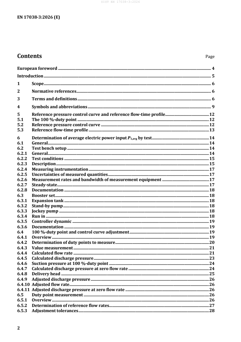
EN 17038-3:2026 is a European Standard from CEN on testing and calculating the Energy Efficiency Index (EEI) of booster sets. It specifies how to determine EEI for rotordynamic pump units used to pump clean water in buildings, either by test or by a semi-analytical model (SAM). The result is a comparative efficiency indicator for manufacturers, installers, and companies placing booster sets on the market or into service, and it does not replace a lifetime cost analysis.
What does EN 17038-3:2026 specify?
EN 17038-3:2026 specifies the methods and procedures for testing, calculating, and determining the EEI of booster sets. In practice, it gives one common way to compare different booster set configurations, including sets with fixed-speed pumps, variable-speed pumps, or a mix of both.
The scope covers booster sets with a maximum hydraulic power of 150 kW and a minimum rated flow of 6 m3/h, intended for open-loop pressure or flow control inside buildings. The document also makes clear that the booster set is a single marketed and/or commissioned product, used for clean water, and without self-priming functionality. Booster sets below 6 m3/h are handled using pumps that comply with EN 17038-2.
The document is organized as follows:
- Clauses 1-4 cover scope, normative references, terms, and symbols.
- Clause 5 defines the reference pressure control curve and the reference flow-time profile.
- Clause 6 gives the test-based method for determining average electric power input.
- Clause 7 gives the SAM-based method for determining average electric power input.
- Clause 8 defines the reference electric power input.
- Clause 9 gives the EEI calculation.
- Annexes A-D provide supporting information on configurations, control behavior, control deviations, and uncertainty.
| Annex | What it covers |
|---|---|
| Annex A | Configurations and modes of operation and control |
| Annex B | Effect of operation mode and type of pressure control on EEI |
| Annex C | Effect of control deviations on EEI |
| Annex D | Uncertainties and tolerances of EEI |
What are the key requirements of EN 17038-3:2026?
EN 17038-3:2026 is built around a reference operating pattern and two ways of determining average electric power input. The practical point is that the EEI is not based on a single operating point - it is based on how the booster set behaves over representative load conditions.
Reference curve and duty point
Clause 5 defines the 100%-duty point as the duty point with maximum hydraulic power at nominal booster set speed. From that point, the standard derives the reference control curve and the reference flow-time profile.
That matters because the 100%-duty point anchors the whole EEI calculation. If the duty point is determined differently, the resulting EEI can change, so the test or SAM must identify it consistently.
Test-based determination of average electric power input
Clause 6 gives the route based on testing a real booster set. The company placing the set on the market or into service performs performance tests, using a test bench, specified instrumentation, and documented uncertainty control.
This matters in practice because the measured flow rate, suction pressure, discharge pressure, and electric power input are used to build the average electric power input for the EEI calculation. Clause 6 also covers how to treat accessible and non-accessible duty points, how to correct suction and discharge pressures, and how to apply penalties and adjusted values where needed.
SAM-based determination of average electric power input
Clause 7 gives the alternative route using a semi-analytical model (SAM). EN 17038-3:2026 treats the booster set as a combination of pump models, electric motor or power drive system models, internal piping and valve losses, auxiliary electrical losses, and pressure/switching control.
This matters because the EEI can be determined without testing every complete booster set, provided the component characteristics are known in the relevant operating range. Clause 7 distinguishes only two operating modes for the calculation - all pumps at fixed speed, or one pump at variable speed - and it also sets the switching logic for fixed-speed and variable-speed booster sets.
Reference operating data and weighting
Clause 7 also uses the reference flow-time profile to calculate a weighted average electric power input. That means the standard does not treat all flows equally - it weights them according to a defined pattern of operation.
For users, this makes the result closer to real service behavior. It also means that increasing and decreasing flow conditions are both relevant for fixed-speed booster sets, while variable-speed booster sets are treated with a correction for control deviations.
Reference electric power input and EEI
Clause 8 defines the reference electric power input using a virtual reference booster set with two fixed-speed pumps, defined pump and motor characteristics, and no auxiliary electrical losses. Clause 9 then calculates EEI as the ratio of average electric power input to reference electric power input.
That ratio is the final result used to rate the booster set. Because the document rounds EEI to two decimal places, small differences in test quality, model quality, or control behavior can affect the final declared value.
Uncertainty and tolerances
Annex D addresses measurement uncertainty, model uncertainty, and total tolerance. This is important for declarations of EEI, especially when a company is reporting a series value or comparing close-performing products.
What terms does EN 17038-3:2026 define?
- Booster set - A single pump unit or a parallel assembly of pump units with backflow prevention and pressure or flow control components, intended to pump clean water in buildings.
- Fixed speed pump - A pump unit without an electronic power converter such as a frequency converter.
- Variable speed pump - A pump unit equipped with an electronic power converter such as a frequency converter.
- Stand-by pump - A pump added for redundancy, beyond the normal demand.
- Jockey pump - A much smaller pump used only for leakage flows or very small demand during cut-in of another pump.
- Reference control curve - The representative pressure control curve defined relative to the 100%-duty point.
- Flow-time profile - The relation between defined flow-rate intervals and relative operating time.
- Complete drive module (CDM) - An electronic power converter with connected extensions such as protection devices, transformers, and auxiliaries.
- Power drive system (PDS) - A combination of a CDM and an electric motor.
Who uses EN 17038-3:2026?
EN 17038-3:2026 is used by manufacturers, system integrators, installers, and other companies that place booster sets on the market or put them into service. It is also relevant to engineering and quality teams that need a repeatable way to measure or model efficiency performance.
In practice, users apply it when they:
- test booster sets and document performance values for EEI calculation,
- build SAMs for product families or configured systems,
- compare fixed-speed and variable-speed booster set designs,
- define control strategies and switching behavior,
- prepare technical documentation for declared efficiency values.
The standard is mainly used in the pumps and building water-supply field, especially for open-loop pressure and flow control inside buildings.
Which standards are used with EN 17038-3:2026?
| Standard | What it contributes |
|---|---|
| EN ISO 9906:2012 | Hydraulic performance acceptance tests for rotodynamic pumps, used as the test basis for measured hydraulic performance |
| EN ISO 17769-1 | General pump terms, definitions, quantities, symbols, and units |
| EN ISO 17769-2 | Pumping system terms, definitions, quantities, symbols, and units |
| EN 60034-1 | Ratings and performance of rotating electrical machines |
| EN IEC 60034-2-1 | Standard methods for determining losses and efficiency of rotating electrical machines |
| EN 60038:2011 | CENELEC standard voltages |
| EN 61800-9-2 | Energy efficiency indicators for adjustable speed power drive systems and motor starters |
| EN IEC 61800-2 | General requirements and rating specifications for low-voltage adjustable speed AC power drive systems |
| EN 17038-1:2019 | The EEI framework referenced for the EEI definition and calculation context |
| EN 17038-2:2019 | The SAM basis for single pump units and related modelling methods used by analogy here |
| EN 16480 | The efficiency reference used in the reference pump definition in Clause 8 |
| EN 60034-30-1 | Motor efficiency class reference used for the reference motor definition in Clause 8 |
What does the EN 17038-3:2026 document contain?
EN 17038-3:2026 contains the reference control curve, the reference flow-time profile, and the procedures for finding the 100%-duty point. It also contains the test-bench requirements, measurement conditions, instrumentation guidance, and the correction steps used to turn test data into average electric power input.
The document further contains the SAM structure for pumps, motors, PDSs, internal piping losses, and auxiliary electrical losses. Tables 1-4 define symbols and indices, Table 5 defines the flow-time profile, and Figures 1-2 illustrate the control curve and flow-time profile. Annex D gives the uncertainty and tolerance framework used when results are measured or modeled.
Get Certified
Connect with accredited certification bodies for this standard

Institut za varilstvo d.o.o. (Welding Institute)
Slovenia's leading welding institute since 1952. ISO 3834, EN 1090, pressure equipment certification, NDT personnel, welder qualification. Only IIW Au
Sponsored listings
Frequently Asked Questions
EN 17038-3:2026 is a standard published by the European Committee for Standardization (CEN). Its full title is "Pumps - Methods of qualification of the Energy Efficiency Index for rotordynamic pump units - Part 3: Testing and calculation of energy efficiency index (EEI) of booster sets". This standard covers: This document specifies methods and procedures for testing, calculating and determining the energy efficiency index (EEI) of booster sets. A booster set is either a single pump unit or an assembly of pump units connected in parallel with a maximum hydraulic power of 150 kW, a minimum rated flow of 6 m3/h (0,001 667 m3/s), operated with backflow prevention and additional components influencing hydraulic performance and with components necessary to control pressure or provide flow in open loops inside buildings and which is placed on the market and/or put into service as one single product and its intended use is to pump clean water and does not have a self-priming functionality. A booster set with a rated flow below 6 m3/h is composed using pumps that comply with EN 17038 2.
This document specifies methods and procedures for testing, calculating and determining the energy efficiency index (EEI) of booster sets. A booster set is either a single pump unit or an assembly of pump units connected in parallel with a maximum hydraulic power of 150 kW, a minimum rated flow of 6 m3/h (0,001 667 m3/s), operated with backflow prevention and additional components influencing hydraulic performance and with components necessary to control pressure or provide flow in open loops inside buildings and which is placed on the market and/or put into service as one single product and its intended use is to pump clean water and does not have a self-priming functionality. A booster set with a rated flow below 6 m3/h is composed using pumps that comply with EN 17038 2.
EN 17038-3:2026 is classified under the following ICS (International Classification for Standards) categories: 23.080 - Pumps. The ICS classification helps identify the subject area and facilitates finding related standards.
EN 17038-3:2026 is available in PDF format for immediate download after purchase. The document can be added to your cart and obtained through the secure checkout process. Digital delivery ensures instant access to the complete standard document.
Standards Content (Sample)
SLOVENSKI STANDARD
01-november-2026
Črpalke - Metode za opredelitev indeksa energijske učinkovitosti centrifugalnih
črpalk - 3. del: Preskušanje in računanje indeksa energijske učinkovitosti (IEE)
ojačevalnih agregatov
Pumps - Methods of qualification of the Energy Efficiency Index for rotordynamic pump
units - Part 3: Testing and calculation of energy efficiency index (EEI) of booster sets
Pumpen - Methoden zur Qualifikation des Energieeffizienzindexes für Kreiselpumpen -
Teil 3: Prüfung und Berechnung des Energieeffizienzindexes (EEI) von
Druckerhöhungsanlagen
Pompes - Méthodes de qualification de l’indice de rendement énergétique des groupes
motopompes rotodynamiques - Partie 3 : Essais et calcul de l’indice de rendement
énergétique (EEI) des groupes de surpression
Ta slovenski standard je istoveten z: EN 17038-3:2026
ICS:
23.080 Črpalke Pumps
2003-01.Slovenski inštitut za standardizacijo. Razmnoževanje celote ali delov tega standarda ni dovoljeno.
EN 17038-3
EUROPEAN STANDARD
NORME EUROPÉENNE
September 2026
EUROPÄISCHE NORM
ICS 23.080
English Version
Pumps - Methods of qualification of the Energy Efficiency
Index for rotordynamic pump units - Part 3: Testing and
calculation of energy efficiency index (EEI) of booster sets
Pompes - Méthodes de qualification de l'indice de Pumpen - Methoden zur Qualifikation des
rendement énergétique des groupes motopompes Energieeffizienzindexes für Kreiselpumpen - Teil 3:
rotodynamiques - Partie 3 : Essais et calcul de l'indice Prüfung und Berechnung des Energieeffizienzindexes
de rendement énergétique (EEI) des groupes de (EEI) von Druckerhöhungsanlagen
surpression
This European Standard was approved by CEN on 3 August 2026.
CEN members are bound to comply with the CEN/CENELEC Internal Regulations which stipulate the conditions for giving this
European Standard the status of a national standard without any alteration. Up-to-date lists and bibliographical references
concerning such national standards may be obtained on application to the CEN-CENELEC Management Centre or to any CEN
member.
This European Standard exists in three official versions (English, French, German). A version in any other language made by
translation under the responsibility of a CEN member into its own language and notified to the CEN-CENELEC Management
Centre has the same status as the official versions.
CEN members are the national standards bodies of Austria, Belgium, Bulgaria, Croatia, Cyprus, Czech Republic, Denmark, Estonia,
Finland, France, Germany, Greece, Hungary, Iceland, Ireland, Italy, Latvia, Lithuania, Luxembourg, Malta, Netherlands, Norway,
Poland, Portugal, Republic of North Macedonia, Romania, Serbia, Slovakia, Slovenia, Spain, Sweden, Switzerland, Türkiye and
United Kingdom.
EUROPEAN COMMITTEE FOR STANDARDIZATION
COMITÉ EUROPÉEN DE NORMALISATION
EUROPÄISCHES KOMITEE FÜR NORMUNG
CEN-CENELEC Management Centre: Rue de la Science 23, B-1040 Brussels
© 2026 CEN All rights of exploitation in any form and by any means reserved Ref. No. EN 17038-3:2026 E
worldwide for CEN national Members.
Contents Page
European foreword . 4
Introduction . 5
1 Scope . 6
2 Normative references . 6
3 Terms and definitions . 6
4 Symbols and abbreviations . 9
5 Reference pressure control curve and reference flow-time profile . 12
5.1 The 100 %-duty point . 12
5.2 Reference pressure control curve . 12
5.3 Reference flow-time profile . 13
6 Determination of average electric power input P by test . 14
1,avg
6.1 General. 14
6.2 Test bench setup . 14
6.2.1 General. 14
6.2.2 Test conditions . 15
6.2.3 Description . 15
6.2.4 Measuring instrumentation . 17
6.2.5 Uncertainties of measured quantities . 17
6.2.6 Measurement rates and bandwidth of measurement equipment . 17
6.2.7 Steady-state . 17
6.2.8 Documentation . 18
6.3 Booster set . 18
6.3.1 Expansion tank . 18
6.3.2 Stand-by pump . 18
6.3.3 Jockey pump . 18
6.3.4 Run in . 18
6.3.5 Controller dynamic . 19
6.3.6 Documentation . 19
6.4 100 %-duty point and control curve adjustment . 19
6.4.1 Overview . 19
6.4.2 Determination of duty points to measure . 20
6.4.3 Value measurement . 21
6.4.4 Calculated flow rate . 21
6.4.5 Calculated discharge pressure . 23
6.4.6 Suction pressure at 100 %-duty point . 24
6.4.7 Calculated discharge pressure at zero flow rate . 24
6.4.8 Delivery head . 25
6.4.9 Adjusted discharge pressure . 26
6.4.10 Adjusted flow rate. 26
6.4.11 Adjusted discharge pressure at zero flow rate . 26
6.5 Duty point measurement . 26
6.5.1 Overview . 26
6.5.2 Determination of reference flow rates . 27
6.5.3 Adjustment tolerances . 28
6.5.4 Value measurement . 29
6.5.5 Duty point not accessible . 30
6.6 Evaluation calculation . 30
6.6.1 Overview . 30
6.6.2 Suction pressure correction . 31
6.6.3 Discharge pressure correction (penalty). 32
6.6.4 Representing values per measured duty point. 34
6.6.5 Flow rate correction . 35
6.6.6 Calculation of P1,avg . 37
7 Determination of average electric power input P by the means of a semi-analytical
1,avg
model (SAM) . 38
7.1 General . 38
7.1.1 General . 38
7.1.2 Stand-by pump . 38
7.1.3 Jockey pump . 38
7.2 General . 38
7.3 Pre-defined mode of operation and version of pressure and switching control. 39
7.4 The semi-analytical model of pumps . 41
7.5 The semi-analytical model of electric motors or of power drive systems (PDSs) . 41
7.6 Modelling internal piping and valve losses . 41
7.7 Auxiliary electrical losses . 42
7.8 Calculation of Q and H . 42
100 % 100 %
7.9 Calculation of P dependent on Q/Q . 43
1 100 %
7.9.1 Booster sets operated at fixed speed . 43
7.9.2 Booster sets operated at variable speed . 46
7.10 Calculation of P . 49
1,avg
8 Determination of reference electric power input P . 50
1,ref
8.1 Definition . 50
8.2 Reference pump hydraulic power . 51
8.3 Reference pump efficiency . 51
8.4 Reference pump shaft power . 51
8.5 Reference motor efficiency . 52
8.6 Reference electric power input . 52
9 Calculation of energy efficiency index (EEI) . 53
Annex A (informative) Configurations and modes of operation and control . 54
Annex B (informative) Effect of operation mode and type of pressure control on EEI . 57
Annex C (informative) Effect of control deviations on EEI . 59
Annex D (informative) Uncertainties and tolerances of EEI . 61
Bibliography . 68
European foreword
This document (EN 17038-3:2026) has been prepared by Technical Committee CEN/TC 197 “Pumps”,
the secretariat of which is held by AFNOR.
This European Standard shall be given the status of a national standard, either by publication of an
identical text or by endorsement, at the latest by March 2027, and conflicting national standards shall be
withdrawn at the latest by March 2027.
Attention is drawn to the possibility that some of the elements of this document may be the subject of
patent rights. CEN shall not be held responsible for identifying any or all such patent rights.
Any feedback and questions on this document should be directed to the users’ national standards body.
A complete listing of these bodies can be found on the CEN website.
According to the CEN-CENELEC Internal Regulations, the national standards organisations of the
following countries are bound to implement this European Standard: Austria, Belgium, Bulgaria, Croatia,
Cyprus, Czech Republic, Denmark, Estonia, Finland, France, Germany, Greece, Hungary, Iceland, Ireland,
Italy, Latvia, Lithuania, Luxembourg, Malta, Netherlands, Norway, Poland, Portugal, Republic of North
Macedonia, Romania, Serbia, Slovakia, Slovenia, Spain, Sweden, Switzerland, Türkiye and the United
Kingdom.
Introduction
This document is the third part of a series of standards describing a methodology to evaluate energy
efficiency performance of booster sets, comprising one or more pump(s), the motor(s) with or without
frequency converter, and additional components influencing hydraulic performance. It is based on a non-
dimensional numerical value called energy efficiency index (EEI). An EEI allows the comparison of
different configurations with one common indicator. Physical influences such as number and size of the
incorporated pump(s), pump unit part-load operation, motor-efficiency characteristic and frequency
converter influence are implemented into this metric.
Specific requirements for testing and a calculation method for EEI, the so-called semi-analytical model
(SAM) of a complete booster set, a specific flow-time profile and a reference control curve are given in
this part of the series of standard.
EEI is an index to rate booster sets according to their energy efficiency but does not replace the need to
do a life-time cost analysis regarding energy consumption over the lifetime of the booster set.
1 Scope
This document specifies methods and procedures for testing, calculating and determining the energy
efficiency index (EEI) of booster sets.
A booster set is either a single pump unit or an assembly of pump units connected in parallel with a
3 3
maximum hydraulic power of 150 kW, a minimum rated flow of 6 m /h (0,001 667 m /s), operated with
backflow prevention and additional components influencing hydraulic performance and with
components necessary to control pressure or provide flow in open loops inside buildings and which is
placed on the market and/or put into service as one single product and its intended use is to pump clean
water and does not have a self-priming functionality.
A booster set with a rated flow below 6 m /h is composed using pumps that comply with EN 17038-2.
2 Normative references
The following documents are referred to in the text in such a way that some or all of their content
constitutes requirements of this document. For dated references, only the edition cited applies. For
undated references, the latest edition of the referenced document (including any amendments) applies.
EN ISO 9906:2012, Rotodynamic pumps — Hydraulic performance acceptance tests — Grades 1, 2 and 3
(ISO 9906:2012)
EN ISO 17769-1, Liquid pumps and installation — General terms, definitions, quantities, letter symbols and
units — Part 1: Liquid pumps (ISO 17769-1)
EN ISO 17769-2, Liquid pumps and installation — General terms, definitions, quantities, letter symbols and
units — Part 2: Pumping System (ISO 17769-2)
EN 60034-1, Rotating electrical machines — Part 1: Rating and performance (IEC 60034-1)
EN IEC 60034-2-1, Rotating electrical machines — Part 2-1: Standard methods for determining losses and
efficiency from tests (excluding machines for traction vehicles) (IEC 60034-2-1)
EN 60038:2011, CENELEC standard voltages (IEC 60038:2009)
EN 61800-9-2, Adjustable speed electrical power drive systems — Part 9-2: Ecodesign for power drive
systems, motor starters, power electronics and their driven applications — Energy efficiency indicators for
power drive systems and motor starters
EN IEC 61800-2, Adjustable speed electrical power drive systems — Part 2: General requirements — Rating
specifications for low voltage adjustable speed AC power drive systems (IEC 61800-2)
3 Terms and definitions
For the purposes of this document, the terms and definitions given in EN ISO 17769-1, EN ISO 17769-2
and the following apply.
ISO and IEC maintain terminology databases for use in standardization at the following addresses:
— ISO Online browsing platform: available at https://www.iso.org/obp/
— IEC Electropedia: available at https://www.electropedia.org/
3.1
booster set
single pump unit or assembly of pump units connected in parallel with a maximum hydraulic power of
3 3
150 kW, a minimum rated flow of 6 m /h (0,001 667 m /s), operated with backflow prevention and
additional components influencing hydraulic performance and with components necessary to control
pressure or provide flow in open loops inside buildings and which is placed on the market and/or put
into service as one single product and its intended use is to pump clean water and does not have a self-
priming functionality
Note 1 to entry: “Clean water” means water with a maximum non-absorbent free solid content of 0,25 kg/m , and
with a maximum dissolved solid content of 50 kg/m , provided that the total gas content of the water does not
exceed the saturation volume. Any additives that are needed to avoid water freezing down to – 10° C shall not be
considered.
[SOURCE: Regulation (EU) 547/2012]
3.2
expansion tank
tank partially filled with air, whose compressibility cushions pressure deviations under balancing small
water volumes between the tank and the connected system
3.3
fixed speed pump
pump unit without an electronic power converter (e.g. frequency converter)
3.4
variable speed pump
pump unit equipped with an electronic power converter (e.g. frequency converter)
3.5
stand-by pump
pump unit which intentionally increases the number of pumps in booster set (3.1) compared to the
installation demand for redundancy reasons
3.6
jockey pump
pump unit sized for considerably less flow than other pumps of the booster set (3.1) and intended only to
handle leakage flows and/or small flows during cut-in of another pump
3.7
suction pressure
pressure at the inlet of a booster set (3.1)
Note 1 to entry: Pressures are gauge pressures (relative to the atmospheric pressure).
3.8
discharge pressure
pressure at the outlet of a booster set (3.1)
Note 1 to entry: Pressures are gauge pressures (relative to the atmospheric pressure).
3.9
total differential head
height at which the water is raised vertically by the booster set (3.1)
3.10
hydraulic power
power of the pumped water transferred by a pump, defined mainly by flow rate and total differential head
(3.9)
3.11
nominal booster set flow rate
design operation flow rate of the booster set (3.1), typically defined by nominal booster set speed (3.12)
and high booster set efficiency, e.g. the best efficiency point of the booster set (resp. the best efficiency
point of one pump multiplied by the pump number)
3.12
nominal booster set speed
maximum speed that the booster set (3.1) is designed to run continuously
3.13
best efficiency point
BEP
pump or booster set (3.1) duty point with highest total efficiency “wire to water”
3.14
100% duty point
duty point of maximum value of the hydraulic power (3.10) at nominal booster set speed (3.12)
Note 1 to entry: It is to be expected more or less close to the nominal booster set duty point.
3.15
control curve
adjusted discharge pressure (3.8) dependent on flow rate of a booster set (3.1)
Note 1 to entry: See also A.2.1.
3.16
reference control curve
representative pressure control curve defined relatively by the 100%-duty point (3.14)
3.17
reference total differential head
total differential head (3.9) defined by the reference control curve (3.16) and the reference flow rate (3.18)
3.18
reference flow rate
flow rate defined by the 100%-duty point (3.14) and the flow-time profile (3.19)
3.19
flow-time profile
relation between defined flow rate intervals and relative operation time
3.20
complete drive module
CDM
electronic power converter connected between the electric supply and a motor as well as extensions such
as protection devices, transformers and auxiliaries
Note 1 to entry: The complete drive module shall be according to EN IEC 61800-2.
3.21
power drive system
PDS
combination of a CDM (3.20) and an electric motor
4 Symbols and abbreviations
The symbols and units given in Tables 1 and 2 and the indices given in Tables 3 and 4 apply.
Table 1 — Symbols and units
Symbol Designation Unit
-
E Uncertainty
(dimensionless)
EEI Energy efficiency index -
EEI Base value of EEI -
base
Η Motor efficiency -
m
Η Pump efficiency -
pump
g Gravitational acceleration m/s
H Total differential head m
H100 %,loss Total differential head loss at 100 %-duty point m
I Duty point -
M Sample number -
n Pump specific speed 1/min
s
K Pressure ratio -
P Electric power input kW
P Average electric power input kW
1,avg
P Reference electric power input kW
1,ref
P Discharge-pressure-corrected electric power input kW
1,pd-corr
P Suction-pressure-corrected electric power input kW
1,ps-corr
P Flow-rate-corrected electric power input kW
1,Q-corr
P Reference pump shaft power kW
2,ref
P Hydraulic power kW
hyd
p Discharge pressure Pa
d
p Suction pressure Pa
s
Symbol Designation Unit
Q Flow rate m /h
z Number of relevant booster set pumps -
Δt / t Time ratio -
tot
ρ Water density kg/m
U Voltage V
I Current A
T63 % Time constant s
A B C D Polynomial parameters hydraulic power -
p p p p
A B C D Polynomial parameters measured discharge pressure -
pd pd pd pd
A B C D Polynomial parameters measured suction pressure -
ps ps ps ps
Table 2 — Additional symbols and units for Clause 7 (SAM)
Symbol Designation Unit
p Minimum pressure Pa
min
p Maximum pressure Pa
max
Q Hysteresis of flow switching from pump II to pump I m /h
II→I
Q Threshold flow when a pump is triggered to switched off m /h
off
Q Steady-state flow after pump switching off m /h
tr
n Rotational pump speed 1/min
j p (1p, 2p, 3p) Booster set characteristic for j running pump -
H Total, internal hydraulic loss m
L,tot
P Pump shaft power kW
P Auxiliary electric losses kW
el,aux
ζ Loss coefficient of the non-return valves -
n.r.v
ζ Loss coefficient of cut-off valves -
c.o.v
ζ Loss coefficient of piping element i -
piping element i
A Nominal suction and discharge cross sections m
N,PU
A Inner cross section of a pipe element i m
i
Q Flow rate of piping element i m /h
piping element i
Q Flow rate of the pump unit m /h
PU
H Total differential head of the pump unit m
PU
A , B , C , D , Polynomial parameters of relative hydraulic power -
hyd hyd hyd hyd
a , b , c , d Polynomial parameters of relative total differential head -
H H H H
s Relative flow factor of running pumps -
Symbol Designation Unit
j Number of actually running pumps -
k Correction factor -
corr
a , b , c , d Polynomial parameters of shaft power -
P P P P
P Nominal motor shaft power kW
N,M
T Shaft torque Nm
D Impeller diameter m
imp
Δt/100 Time ratio -
CD Correction factor for control deviation -
corr
F Sensitivity factor -
t Manufacturing tolerance -
EEI
Table 3 — Indices
Indices Designation
0 % At zero flow rate
10 % At 10 %-duty point
… …
100 % At 100 %-duty point
adj Adjusted
BEP Best efficiency point
calc Calculated
dec Decreasing flow measurement
exp Expected
i At duty point i
i+10 % At duty point i+10 %
inc Increasing flow measurement
meas Measured
rate Rated
ref Reference
Table 4 — Additional indices for Clause 7 (SAM)
Indices Designation
N_PU Nominal pump unit
tot Total
L Loss
PU Pump unit
Indices Designation
hyd Hydraulic
inc Referring to increasing quantities
dec Referring to decreasing quantities
var Variable speed pump
fix Fixed speed pump
5 Reference pressure control curve and reference flow-time profile
5.1 The 100 %-duty point
The 100 %-duty point is defined as duty point of maximum hydraulic power at nominal booster set speed,
see 3.11.
The flow rate at 100 %-duty point Q is defined as flow rate of that duty point.
100 %
The total differential head at 100 %-duty point H is defined as total differential head of the that same
100 %
duty point.
For details of determination see Clause 6.
5.2 Reference pressure control curve
The reference control curve for booster sets is defined by Formula (1):
Q
HH ⋅ 0,,75+⋅0 25 (1)
ref 100%
Q
100%
where
H is the reference total differential head in m;
ref
H is the total differential head at 100 %-duty point in m;
100 %
Q is the flow rate in m /h;
Q is the flow rate at 100 %-duty point in m /h.
100 %
See Figure 1 for illustration of a Q-H-curve field of an example booster set with three pumps.
=
Key
100 % 100 % duty point
p reference discharge pressure in Pa
d,ref
Figure 1 — Reference pressure control curve
NOTE Annex A and Annex C describe the different control methods for booster sets. Sets with only fixed speed
pumps will follow a curve of higher pressure based on the Q-H-curve of the pumps and the constant (minimum)
pressure setting of the control. Sets which can follow the reference pressure control curve will show a better energy
efficiency index (EEI). Sets with fixed speed pumps programmed to follow the reference pressure control (as best
they can) will have a better energy efficiency index (EEI) than if programmed for constant pressure.
5.3 Reference flow-time profile
The reference flow-time profile for booster sets is defined in Table 5.
Table 5 — Reference flow-time profile for booster sets
Duty point i 10 % 20 % 30 % 50 % 60 % 70 % 80 % 90 % 100 %
%
Q / Q 40
100 %
Flow ratio 10 % 20 % 30 % 50 % 60 % 70 % 80 % 90 % 100 %
%
Δt / t 19
tot
Time ratio 6 % 21 % 26 % 12 % 6 % 4 % 3 % 2 % 1 %
%
See Figure 2 for a diagram showing the flow-time profile.
Key
Δt / ttot time ratio
Q / Q100 % flow ratio
Figure 2 — Flow-time profile
6 Determination of average electric power input P by test
1,avg
6.1 General
This clause specifies performance tests and evaluations on booster sets which are carried out by a
company which places the booster set on the market and/or puts it into service; Such tests shall provide
the necessary information on the actual performance values of test booster sets needed for the calculation
of the EEI-value according to its definition given in EN 17038-1:2019 , Clause 4.
6.2 Test bench setup
6.2.1 General
All provisions for the test concerning the booster set (taken as “black box” and treated as a pump unit
such as described in EN 17038-2) shall be in accordance with EN ISO 9906, grade 2. The exception for
power of 10 kW and below (as allowed for the application of EN ISO 9906 on acceptance tests) shall not
be valid.
All provisions for the test concerning electric motors if they are part of the booster set and are fed directly
from an electric grid shall be in accordance with EN IEC 60034-2-1.
All provisions for the test concerning a power drive system if is part of the booster set shall be in
accordance with EN 61800-9-2.
As impacted by EN 17038-1:2019/AC:2021.
6.2.2 Test conditions
Tests shall be carried out with clean cold water, that means:
–6 2
— a maximum kinematic viscosity of 1,5 × 10 m /s;
— a maximum density of 1 050 kg/m ; and
— a maximum temperature of 40° C.
To obtain repeatable results, test duration shall be sufficient as well as it is recommended to keep stable
test conditions; especially run-in and warming-up effects of the electric and electronic components of the
unit shall be considered. Run-in effects can take up to one day operating time.
The electric power supply of the test installation shall fulfil the requirements as specified in EN 60034-1.
This requires that:
— the voltage shall be in accordance with EN 60038:2011, 7.2, and EN 60034-1,
— the frequency shall be within ± 0,3 % of the rated frequency during measurements.
6.2.3 Description
An open loop test bench design shall be used, either with supply tank as illustrated in Figure 3, or with
sufficient fresh water supply.
Key
P1 electric power input
pd discharge pressure
ps suction pressure
Q flow rate
Figure 3 — Test bench design
The pressure sensors at suction and discharge side shall be as close as possible to the booster set, but
negative flow impact e.g. by swirls shall be avoided.
As the pressure difference is evaluated, both pressure measuring instruments shall be at the same
geodetic height, especially with booster set manifolds at different geodetic heights. If necessary, value-
offsetting is allowed to equalize both pressure sensor values in unpressurized state.
The flow measurement inlet and outlet distances shall be kept. Preferred positioning is on booster set
suction side.
The suction pressure shall be atmospheric pressure. Further the suction pressure shall be independent
of the flow. Choose a test bench design with low piping losses on suction side (short pipe lengths and big
pipe diameter). If necessary, position the flow measurement at booster set discharge side.
NOTE Booster sets are operated in open loop systems with geodetic head. In the case of large geodetic height
not all operating points are accessible for fixed speed pumps due to the switching of the pumps. To keep the gaps in
the accessible flow as small as possible, a hydraulic loop without geodetic head is used for the determination of EEI.
Then, the resistance curves which determine the operating points of the booster set are purely parabolic (without
geodetic part).
In practical booster set operation in a test bench there is typically a certain suction pressure. Further the
suction pressure is impacted by hydraulic losses of the test bench, resulting in higher suction pressure
values at part load. As the reference pressure control curve remains fixed, deviating suction pressure
leads to deviating delivery head, see Figure 4.
Figure 4 — Suction pressure deviation
To be independent of test bench behaviour, the suction pressure at 100 %-duty point p is
s,100 %
determined and considered as constant for later calculation, see subclause 6.4.6.
Deviating suction pressure from this suction pressure at 100 %-duty point p is corrected by
s,100 %
electrical power scaling, see subclause 6.6.2. The booster set efficiency is assumed to be constant.
However, the booster set efficiency is assumed to be constant for scaling, any suction pressure variation
from the 100 %-suction pressure at 100 %-duty point p shall not exceed 20 % of the total differential
s,100 %
head of the booster set H , see Formula (2).
100 %
p − p ≤ 02, ⋅ρ ⋅gH ⋅ (2)
s,100%%s,meas 100
where
p is the suction pressure at 100 %-duty point in Pa;
s,100 %
p is the measured suction pressure in Pa;
s,meas
ρ is the water density at 20° C temperature, 998,2 kg/m ;
g is the gravitational acceleration, 9,81 m/s;
H is the total differential head at 100 %-duty point in m .
100 %
6.2.4 Measuring instrumentation
Measuring instrumentation is needed for the determination of:
— the flow rate Q;
— the suction pressure p ;
s
— the discharge pressure p ;
d
— the electric power input P .
The measuring equipment needed to determine the flow rate Q, the suction pressure p and the discharge
s
pressure p shall be selected in accordance with EN ISO 9906:2012.
d
Detailed information is given in EN ISO 9906:2012, Annex A.1.
Since instrument accuracy is generally expressed as a percentage of full scale, the range of the
instruments chosen shall be as small as practical.
The electric power input P of the booster set is determined based on input voltages U and input
currents I. All requirements concerning the instrumentation for the measurements of electric power
input P shall be fulfilled according to EN IEC 60034-2-1.
6.2.5 Uncertainties of measured quantities
The total measurement uncertainties of:
— the flow rate Q;
— the suction pressure p ;
s
— the discharge pressure p ;
d
— the electric power input P .
result from the combined effects of the measurement device uncertainty and of the random uncertainty
and can be determined as described in EN 17038-1:2019, Annex D.
NOTE For tests done by a company which is responsible for the qualification of booster sets (see
EN 17038-1:2019, Clause 5) it is advisable to achieve total measurement uncertainties to be as small as possible, i.e.
smaller than the maximum permissible values specified by standards.
6.2.6 Measurement rates and bandwidth of measurement equipment
All measurement devices shall have a time constant (T ) in the range between (0,1 – 0,6) s.
63 %
6.2.7 Steady-state
All measurements shall be made under hydraulic and thermal steady-state conditions, see
— EN ISO 9906;
— EN IEC 60034-2-1;
— EN 60034-2-2;
— EN IEC 60034-2-3; and
— EN 61800-9-2.
NOTE EN 61800-9-2 requests thermal stability for the PDS for measuring the maximum duty point. All other
points can be measured quickly after measuring maximum load without waiting for the thermal stability.
6.2.8 Documentation
All measured and calculated values shall be documented.
6.3 Booster set
6.3.1 Expansion tank
If an expansion tank is integrated in the booster set, it shall be deactivated except in case the volume of
the tank is below ten litres plus one litre per every m /h of the flow rate at 100 %-duty point Q . As
100 %
this 100 %-duty point Q is not yet determined at this time, the nominal booster set flow as defined in
100 %
3.11 may be used as representative.
See the example cases in Table 6.
Table 6 — Expansion tank size example cases
Flow rate at 100 %- Integrated expansion tank Action for
duty point Q measurements
100 %
Allowed maximum volume Installed volume
8 m /h 18 l (10 + 8) 12 l Activation
13 m /h 23 l (10 + 13) 25 l Deactivation
NOTE An expansion tank of the maximum allowed volume defined above could be necessary during tests in
respect to the time-transient behaviour of the pressure control of variable speed booster sets.
6.3.2 Stand-by pump
If a stand-by pump as defined in 3.5 is integrated in the booster set, it shall be taken as one of the total
numbers of normal operating pumps for the determination of energy efficiency index (EEI).
6.3.3 Jockey pump
If in the booster set a jockey pump as defined in 3.6 is installed it shall be deactivated and isolated for test
purposes.
6.3.4 Run in
Run-in effects may affect the power consumption of a booster set during its initial operation.
To ensure a representative electric power input a run in of the booster is necessary.
Run in effects can take up to one day operating time.
It is possible to run in the booster set with all pumps running at maximum speed and at different flows.
6.3.5 Controller dynamic
Booster sets to be operated inside buildings typically have default control settings according to building
characteristics. The test bench shall represent the building installation but of course differs in terms of
water volume and installation dynamic. This deviation may lead to unwanted dynamic control effects.
The booster set controller dynamic like PID-parameters may be adjusted according to the particular test
bench to prevent these unwanted dynamic control effects. The adjustment shall be the same for all
measured duty points.
NOTE PID refers to the Proportional – Integral – Derivative gains of the pressure control loop.
6.3.6 Documentation
All booster set adjustments like deactivated expansion tank, jockey pump deactivation, control curve
adjustment and controller dynamic shall be documented.
6.4 100 %-duty point and control curve adjustment
6.4.1 Overview
The reference pressure control curve as described in 5.2 is defined as straight line between two duty
points as shown in Figure 5:
— The 100 %-duty point as duty point of maximum hydraulic power (Q = Q , H = H ).
100 % 100 %
This duty point shall be determined by test in advance. It goes along with the booster set operated with
all relevant booster pumps1 at nominal booster set speed2;
— The zero-flow rate duty point with reduced delivery head (Q = 0 ; H = 0,75 H100 %).
For EEI-determination, this duty point is not evaluated. But if the booster set is able to operate in variable
pressure control as described in A.2.1, it needs to be determined for correct control curve
adjustment.
Key
100 % 100 %-duty point
0 % zero flow rate
Q flow rate
H total differential head
p reference discharge pressure in Pa
d,ref
Figure 5 — Reference pressure control curve
The main steps of determination and adjustment are:
— Measure several duty points around an expected 100 %-duty point at maximum speed.
— Calculate the hydraulic power and find the maximum by approximating a polynom function.
— Determine the flow rate, the discharge pressure and the suction pressure at 100 %-duty point.
— Adjust the booster set control curve according to the calculated values.
NOTE 1 See handling of standby-pumps in subclause 6.3.2 and handling of jockey pumps in subclause 6.3.3.
NOTE 2 See definition in 3.12.
6.4.2 Determination of duty points to measure
To determine the flow rate of 100 %-duty point Q by measurement, duty points around an expected
100 %
flow rate of 100 %-duty point Q are measured and the hydraulic power evaluated.
100 %,exp
The flow rate of the 100 %-duty point Q can be expected close to the booster set nominal duty point
100 %
flow rate given by booster set designation, documentation or nameplate. Alternatively, the booster set
nominal flow rate can also be estimated by the product of pump number and nominal pump flow rate
given by the pump designation, documentation or nameplate.
It is important to take measurement data in a sufficiently large flow rate range around the expected value
of Q .
100 %,exp
Recommended
...