

SIST EN 18208:2027
(Main)Liquid-to-liquid single-phase heat exchangers - Test procedure for determining performance
- Abstract
This document defines the general terms and the calculations used to determine the thermohydraulic performance of heat exchangers. It includes the general test procedure and related theories.
This document is intended to be used for acceptance-testing heat exchangers in test facilities such as laboratories, manufacturer test facilities and final installation site.
This document specifies three acceptance levels:
— level 1 for minimum tolerances;
— level 2 for nominal tolerances;
— level 3 for maximum tolerances;
This document constitutes an application-specific standard in line with EN 305 and EN 306.
- Status
- Published
- Public Enquiry End Date
- 30-Sep-2025
- Publication Date
- 11-Nov-2026
- Technical Committee
- OGS - Heating for buildings
- Current Stage
- 6060 - National Implementation/Publication (Adopted Project)
- Start Date
- 11-Nov-2026
- Due Date
- 16-Jan-2027
- Completion Date
- 12-Nov-2026

SIST EN 18208:2027 is a Slovenian standard for liquid-to-liquid single-phase heat exchangers, published by SIST. It specifies the test procedure for determining thermohydraulic performance, including the calculations, measurement methods and acceptance levels used for acceptance testing by laboratories, manufacturers and users.
What does SIST EN 18208:2027 specify?
SIST EN 18208:2027 defines the general terms and calculations used to determine the thermohydraulic performance of liquid-to-liquid single-phase heat exchangers. It also sets out the general test procedure and the related theory for acceptance testing.
The document is intended for use in laboratories, manufacturer test facilities and at the final installation site. It also specifies three acceptance levels - minimum, nominal and maximum tolerances - so the parties to a test can agree how strict the evaluation should be.
SIST EN 18208:2027 is organized into clauses 1 to 6, followed by three informative annexes and a bibliography. The structure matters because the main clauses cover definitions, performance calculation, test practice and reporting, while the annexes give supporting calculation and reporting material.
| Annex | What it covers |
|---|---|
| Annex A | Calculation of thermal performance uncertainty according to the LMTD method |
| Annex B | Test report template |
| Annex C | Example of test |
What are the key requirements of SIST EN 18208:2027?
SIST EN 18208:2027 focuses on how to define a test case, measure performance, judge acceptability and report the result. In practice, the standard links the thermal design point, the test bench and the uncertainty budget so that the result can be compared with the required performance.
Clause 5.1.2 defines the rated conditions used to describe a heat exchanger: liquid type, mass flow rate, inlet and outlet temperatures, pressures, pressure drops, liquid properties, material properties, fouling state, auxiliary equipment and environmental constraints. This matters because the test result is only meaningful when it is tied to a clearly stated operating condition.
Clause 5.1.2.5 gives the fouling expressions for fouling thermal resistance, excess surface heat transfer coefficient and cleanliness factor. For new heat exchangers, the cleanliness factor is taken as 1. In practice, this lets a user compare a clean test with a fouled design state and quantify degradation.
Clause 5.2 defines hydraulic performance through pressure drop and velocity relations based on Bernoulli's theorem. This is the basis for checking whether the exchanger meets the allowed pressure-loss limit in the plant.
Clause 5.3.1 to 5.3.4 define the thermal performance calculation using energy balance, heat transfer rate, heat transfer coefficients and heat transfer surface. The document recommends using the overall heat transfer coefficient, which matters because it combines convection and conduction effects into one value for comparison.
Clause 5.3.5 presents two calculation routes: LMTD and NTU. The LMTD method is used to determine transfer surface or thermal performance from inlet and outlet temperatures, while the NTU method is used once geometry is established, especially for simulations. This gives users a consistent way to design, test and model the same exchanger.
Clause 6.1 sets the test procedure and test bench conditions. The exchanger should be tested under conditions close to the reference state, with appropriate auxiliary equipment, sealing, purging and sensor installation. The test programme must be agreed by the customer, manufacturer and verifier, and it must include a risk and opportunity analysis, the loop description and the performance test procedure.
Clause 6.1.2 and 6.1.3 define acceptance criteria and steady-state test conditions. The document uses customer-agreed tolerances, stability checks and quality criteria comparing primary and secondary heat transfer rates. The test period starts only after steady-state has been reached and should run long enough to record repeatable data.
Clause 6.2 sets measurement and uncertainty expectations. Instruments are to be calibrated, documented and used according to the required acceptance level. The standard distinguishes laboratory, factory and in situ measurements and gives allowable fluctuation and overall uncertainty ranges for flow, pressure, temperature, hydraulic performance and thermal performance.
Clause 6.3 explains how to transpose results to reference conditions. For new or replacement heat exchangers and for exchangers already in use, the document gives a way to adjust test results using thermal and hydraulic correlations and a model coefficient. This is important when the test cannot exactly match the design conditions.
What terms does SIST EN 18208:2027 define?
SIST EN 18208:2027 uses a set of terms that are central to testing and comparing exchanger performance.
- Thermohydraulic performance of a heat exchanger - the performance expressed through measured or calculated temperatures, flow rates, pressures, pressure drops, heat transfer rate, heat transfer coefficient and fouling factors.
- Primary liquid - the hotter liquid, which acts as the heat source.
- Secondary liquid - the cooler liquid, which acts as the heat sink.
- Fouling - an unwanted deposit layer that increases resistance to heat transfer.
- Pinch temperature - the minimum temperature difference between the primary and secondary liquids.
- Design state (reference conditions) - the operating conditions used to determine the required thermal performance.
- LMTD (log mean temperature difference) - the temperature-difference value used in the LMTD thermal method.
- NTU (number of thermal transfer units) - a dimensionless measure used in the NTU method and in simulation.
Who uses SIST EN 18208:2027?
SIST EN 18208:2027 is used by heat exchanger manufacturers, customers, laboratories and verifiers. It is also relevant to users who need acceptance testing of exchangers in operation or at the installation site.
Manufacturers use it to define the rated conditions, prepare the test programme and transpose test results to design conditions. Customers use it to set acceptance levels and thermal or hydraulic criteria. Laboratories and verifiers use it to plan instrumentation, run the test, assess uncertainty and prepare the report. Site teams use it when the exchanger must be checked in situ, especially when reference conditions cannot be reproduced exactly.
Which standards are used with SIST EN 18208:2027?
SIST EN 18208:2027 refers to several standards that supply terminology, measurement methods and flow measurement guidance.
- EN 247 - provides the heat exchanger terminology used by the document.
- EN 305 - gives the general definitions of heat exchanger performance and the general test procedure framework.
- EN 306 - provides methods for measuring the parameters needed to establish performance.
- EN ISO 5167 (all parts) - gives the flow measurement method for pressure differential devices in full circular conduits.
- ISO/TR 12767 - gives guidance on the effect of departures from ISO 5167 specifications and operating conditions.
- EN ISO/IEC 17025 - is used in the measurement clauses for calibration and competence of testing and calibration laboratories.
- EN 307 - is listed in the references as guidance for installation, operating and maintenance instructions that help maintain performance.
What does the SIST EN 18208:2027 document contain?
SIST EN 18208:2027 contains the calculation framework, test procedure and reporting structure for performance testing of liquid-to-liquid single-phase heat exchangers. It includes formulas for fouling, pressure drop, energy balance, heat transfer rate, LMTD, NTU and thermal efficiency.
The document also contains figures for counter-current and co-current flow, plus diagrams for the relationship between efficiency, NTU and heat flow ratio. Tables set the acceptable amplitudes of fluctuations and overall uncertainties for the different acceptance levels.
Annex A gives an uncertainty calculation method for thermal performance based on the LMTD approach, including combined uncertainty treatment. Annex B provides a report template with the data and appendices to include. Annex C works through a complete water/water shell-and-tube example, including thermal performance, uncertainty evaluation, transposition to reference conditions and pressure-drop assessment.
Get Certified
Connect with accredited certification bodies for this standard

DNV
DNV is an independent assurance and risk management provider.

Lloyd's Register
Lloyd's Register is a global professional services organisation specialising in engineering and technology.
DNV Energy Systems
Energy and renewable energy certification.
Sponsored listings
Frequently Asked Questions
SIST EN 18208:2027 is a standard published by the Slovenian Institute for Standardization (SIST). Its full title is "Liquid-to-liquid single-phase heat exchangers - Test procedure for determining performance". This standard covers: This document defines the general terms and the calculations used to determine the thermohydraulic performance of heat exchangers. It includes the general test procedure and related theories. This document is intended to be used for acceptance-testing heat exchangers in test facilities such as laboratories, manufacturer test facilities and final installation site. This document specifies three acceptance levels: — level 1 for minimum tolerances; — level 2 for nominal tolerances; — level 3 for maximum tolerances; This document constitutes an application-specific standard in line with EN 305 and EN 306.
This document defines the general terms and the calculations used to determine the thermohydraulic performance of heat exchangers. It includes the general test procedure and related theories. This document is intended to be used for acceptance-testing heat exchangers in test facilities such as laboratories, manufacturer test facilities and final installation site. This document specifies three acceptance levels: — level 1 for minimum tolerances; — level 2 for nominal tolerances; — level 3 for maximum tolerances; This document constitutes an application-specific standard in line with EN 305 and EN 306.
SIST EN 18208:2027 is classified under the following ICS (International Classification for Standards) categories: 27.060.30 - Boilers and heat exchangers. The ICS classification helps identify the subject area and facilitates finding related standards.
SIST EN 18208:2027 is available in PDF format for immediate download after purchase. The document can be added to your cart and obtained through the secure checkout process. Digital delivery ensures instant access to the complete standard document.
Standards Content (Sample)
SLOVENSKI STANDARD
01-januar-2027
Enofazni prenosniki toplote tekočina-tekočina - Preskusni postopek za določanje
zmogljivosti
Liquid-to-liquid single-phase heat exchangers - Test procedure for determining
performance
Einphasen-flüssig/flüssig Wärmetauscher - Prüfverfahren zur Bestimmung der
Leistungskriterien
Echangeurs monophasiques liquide/liquide - Procédure d'essai pour la détermination de
la performance
Ta slovenski standard je istoveten z: EN 18208:2026
ICS:
27.060.30 Grelniki vode in prenosniki Boilers and heat exchangers
toplote
2003-01.Slovenski inštitut za standardizacijo. Razmnoževanje celote ali delov tega standarda ni dovoljeno.
EN 18208
EUROPEAN STANDARD
NORME EUROPÉENNE
October 2026
EUROPÄISCHE NORM
ICS 27.060.30
English Version
Liquid-to-liquid single-phase heat exchangers - Test
procedure for determining performance
Echangeurs monophasiques liquide/liquide - Einphasen-flüssig/flüssig Wärmetauscher -
Procédure d'essai pour la détermination de la Prüfverfahren zur Bestimmung der Leistungskriterien
performance
This European Standard was approved by CEN on 14 September 2026.
CEN members are bound to comply with the CEN/CENELEC Internal Regulations which stipulate the conditions for giving this
European Standard the status of a national standard without any alteration. Up-to-date lists and bibliographical references
concerning such national standards may be obtained on application to the CEN-CENELEC Management Centre or to any CEN
member.
This European Standard exists in three official versions (English, French, German). A version in any other language made by
translation under the responsibility of a CEN member into its own language and notified to the CEN-CENELEC Management
Centre has the same status as the official versions.
CEN members are the national standards bodies of Austria, Belgium, Bulgaria, Croatia, Cyprus, Czech Republic, Denmark, Estonia,
Finland, France, Germany, Greece, Hungary, Iceland, Ireland, Italy, Latvia, Lithuania, Luxembourg, Malta, Netherlands, Norway,
Poland, Portugal, Republic of North Macedonia, Romania, Serbia, Slovakia, Slovenia, Spain, Sweden, Switzerland, Türkiye and
United Kingdom.
EUROPEAN COMMITTEE FOR STANDARDIZATION
COMITÉ EUROPÉEN DE NORMALISATION
EUROPÄISCHES KOMITEE FÜR NORMUNG
CEN-CENELEC Management Centre: Rue de la Science 23, B-1040 Brussels
© 2026 CEN All rights of exploitation in any form and by any means reserved Ref. No. EN 18208:2026 E
worldwide for CEN national Members.
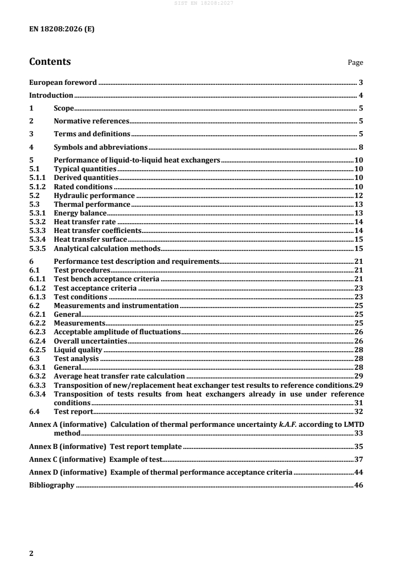
Contents Page
European foreword . 3
Introduction . 4
1 Scope . 5
2 Normative references . 5
3 Terms and definitions . 5
4 Symbols and abbreviations . 8
5 Performance of liquid-to-liquid heat exchangers . 10
5.1 Typical quantities . 10
5.1.1 Derived quantities . 10
5.1.2 Rated conditions . 10
5.2 Hydraulic performance . 12
5.3 Thermal performance . 13
5.3.1 Energy balance . 13
5.3.2 Heat transfer rate . 14
5.3.3 Heat transfer coefficients . 14
5.3.4 Heat transfer surface . 15
5.3.5 Analytical calculation methods . 15
6 Performance test description and requirements. 21
6.1 Test procedures . 21
6.1.1 Test bench acceptance criteria . 21
6.1.2 Test acceptance criteria . 23
6.1.3 Test conditions . 23
6.2 Measurements and instrumentation . 25
6.2.1 General. 25
6.2.2 Measurements . 25
6.2.3 Acceptable amplitude of fluctuations . 26
6.2.4 Overall uncertainties . 26
6.2.5 Liquid quality . 28
6.3 Test analysis . 28
6.3.1 General. 28
6.3.2 Average heat transfer rate calculation . 29
6.3.3 Transposition of new/replacement heat exchanger test results to reference conditions . 29
6.3.4 Transposition of tests results from heat exchangers already in use under reference
conditions . 31
6.4 Test report . 32
Annex A (informative) Calculation of thermal performance uncertainty k.A.F. according to LMTD
method . 33
Annex B (informative) Test report template . 35
Annex C (informative) Example of test . 37
Annex D (informative) Example of thermal performance acceptance criteria . 44
Bibliography . 46
European foreword
This document (EN 18208:2026) has been prepared by Technical Committee CEN/TC 110 “Heat
exchangers”, the secretariat of which is held by DIN.
This European Standard shall be given the status of a national standard, either by publication of an
identical text or by endorsement, at the latest by April 2027, and conflicting national standards shall be
withdrawn at the latest by April 2027.
Attention is drawn to the possibility that some of the elements of this document may be the subject of
patent rights. CEN shall not be held responsible for identifying any or all such patent rights.
Any feedback and questions on this document should be directed to the users’ national standards body.
A complete listing of these bodies can be found on the CEN website.
According to the CEN-CENELEC Internal Regulations, the national standards organisations of the
following countries are bound to implement this European Standard: Austria, Belgium, Bulgaria, Croatia,
Cyprus, Czech Republic, Denmark, Estonia, Finland, France, Germany, Greece, Hungary, Iceland, Ireland,
Italy, Latvia, Lithuania, Luxembourg, Malta, Netherlands, Norway, Poland, Portugal, Republic of North
Macedonia, Romania, Serbia, Slovakia, Slovenia, Spain, Sweden, Switzerland, Türkiye and the United
Kingdom.
Introduction
This document is designed to support a series of European standards dedicated to heat exchangers.
This document provides manufacturers and users with the information needed to present the
thermohydraulic performance characteristics of a heat exchanger. These characteristics form the basis
for evaluating the state of a heat exchanger, whether it is new/a replacement, or already in operation.
This document also provides a performance-based acceptance test procedure for a liquid-to-liquid single-
phase heat exchanger (sensor calibration, acknowledgement of uncertainties, standardization of physical
properties of liquids) and the possible transpositions under various rated conditions.
The customer's technical specification, referred to in this document, defines or adapts the level of
tolerance. It also defines thermal performance acceptance criteria. Examples are provided in Annex C.
Underlying assumption of this document is that the liquid is a Newtonian fluid in turbulent conditions.
This document may be adapted for other liquids or conditions, as agreed by parties involved in the
performance test.
1 Scope
This document defines the general terms and the calculations used to determine the thermohydraulic
performance of heat exchangers. It includes the general test procedure and related theories.
This document is intended to be used for acceptance-testing heat exchangers in test facilities such as
laboratories, manufacturer test facilities and final installation site.
This document specifies three acceptance levels:
— level 1 for minimum tolerances;
— level 2 for nominal tolerances;
— level 3 for maximum tolerances;
This document constitutes an application-specific standard in line with EN 305 and EN 306.
2 Normative references
The following documents are referred to in the text in such a way that some or all of their content
constitutes requirements of this document. For dated references, only the edition cited applies. For
undated references, the latest edition of the referenced document (including any amendments) applies.
EN 247, Heat exchangers — Terminology
EN 305, Heat exchangers — Definitions of performance of heat exchangers and the general test procedure
for establishing performance of all heat exchangers
EN 306, Heat exchangers — Methods of measuring the parameters necessary for establishing the
performance
EN ISO 5167 (all parts), Measurement of fluid flow by means of pressure differential devices inserted in
circular cross-section conduits running full
ISO/TR 12767, Measurement of fluid flow by means of pressure differential devices — Guidelines on the
effect of departure from the specifications and operating conditions given in ISO 5167
3 Terms and definitions
For the purposes of this document, the terms and definitions given in EN 247 and the following apply.
ISO and IEC maintain terminology databases for use in standardization at the following addresses:
— ISO Online browsing platform: available at https://www.iso.org/obp/
— IEC Electropedia: available at https://www.electropedia.org/
3.1
liquid
any type of liquid, such as water, used to transfer thermal energy (heat)
Note 1 to entry: There can be a combination of two or more types of liquids, all in the same phase state (single-
phase liquid).
3.2
primary liquid
hottest liquid, which serves as a heat source
3.3
secondary liquid
coolest liquid, which serves as a heat sink
3.4
mixture
liquid with two or more elements, all in the same phase state
3.5
heat exchanger
device designed to transfer heat between two physically separated liquids
3.6
thermohydraulic performance of a heat exchanger
heat exchanger thermohydraulic performance that can be established by measuring, or can be calculated
using measured parameters, and is expressed according to one or more of the following elements:
— temperature of primary/secondary liquid;
— flow rate of primary/secondary liquid;
— pressure of primary/secondary liquid;
— temperature difference;
— heat transfer coefficient;
— heat transfer rate transferred by primary liquid / captured by secondary liquid;
— pressure drops;
— fouling factors.
Note 1 to entry: These elements are identified per EN 305 and may be established by measuring per EN 306.
3.7
heat exchanger categories
classification of heat exchanger types based on design criteria, physical criteria, or a mix of the two
3.8
heating
temperature increase of a secondary liquid that does not change its phase state
3.9
cooling
temperature decrease of a primary liquid that does not change its phase state
3.10
fouling
deposit of a layer of unwanted materials entailing/causing resistance to the heat transfer
3.11
plugging
obstruction of one or more openings/channels in a heat exchanger where no primary or secondary liquid
can circulate, resulting in a decrease in the transfer surface and an increase in pressure drops
3.12
irreversible pressure drop
decrease of static pressure between inlet and outlet not including change of level
3.13
typical inlet
inlet considered the most representative of each heat exchanger, chosen by the manufacturer or in
accordance with the installation conditions
3.14
typical outlet
outlet considered the most representative of each heat exchanger, chosen by the manufacturer or in
accordance with the conditions of use
3.15
pinch temperature
minimum difference between the primary liquid and secondary liquid temperatures
3.16
customer
user
entity that purchases a good or service from a supplier
Note 1 to entry: For test of used heat exchangers, the user is responsible of the fouling of the heat exchanger. (i.e.
for cleaning it or defining the fouling resistance)
3.17
maker
manufacturer
supplier
entity that supplies goods to a user and guarantees the performance of the heat exchanger (sourcing,
manufacture, production inspection, packaging, storage, transport)
Note 1 to entry: For new heat exchangers, in the case of performance tests, they are also responsible for checking
heat exchanger cleanliness (initial cleanliness report), preparing the heat exchanger and its immediate environment
(e.g. anchoring, adapters, cradles, access scaffolding) and establishing the thermohydraulic criterion checking
report (by transposition if the conditions differ from the reference conditions, per 6.3).
3.18
verifier
laboratory
entity that verifies the equipment performance through one or more tests and ensures the exchanger test
measurements (calibration, test bench assembly, bench cleanliness check, sensor installation, liquid
analysis report, acquisition chain, test bench/heat exchanger adapters connection, performance test,
uncertainty calculations), including measurement uncertainties
3.19
design state
reference conditions
heat exchanger operating parameters that will determine the minimum k.A.F. coefficient required to
satisfy the customer's criterion
Note 1 to entry: This state is determined by the manufacturer based on the operating situations required by the
customer (mass flow rates and liquid temperatures, heat transfer rate to be transferred, etc.)
3.20
steady state
condition where the average value of all main variables of the heat exchanger (temperature, pressure,
flow rate) remains constant over time, and fluctuations are in the same order of magnitude of the
measuring sensor, given that external conditions and inputs are unchanging
Note 1 to entry: Steady-state criteria are expressed in 6.1.3.
3.21
required
thermohydraulic rated conditions according to customer requirements
4 Symbols and abbreviations
For the purposes of this document, the symbols, abbreviations and subscripts given in Table 1 apply.
Table 1 — Symbols, abbreviations, subscripts and units
Symbol Denomination Unit
A Reference heat transfer surface area m
C Hydraulic test factor —
DP
C Thermal test factor —
e
C Cleanliness factor —
foul
C Constant pressure specific heat capacity J/(kg °C)
p
F LMTD correction factor —
g Acceleration of gravity m/s
h Specific enthalpy J/kg
k Overall heat transfer coefficient W/(m °C)
k·A·F Heat exchanger thermal performance W/°C
LMTD Log mean temperature difference °C
NTU Number of thermal transfer units —
p Pressure Pa
q Mass flow kg/s
m
q c Heat capacity flow rate W/°C
m p
R Resistance (thermal) (m °C)/W
S Liquid flow section m
Symbol Denomination Unit
SM Excess surface heat transfer coefficient %
T Celsius temperature °C
U Absolute uncertainty —
v Velocity m/s
x Overall heat transfer coefficient margin %
y Heat flow ratio —
z Height m
α Convective heat transfer coefficient W/(m °C)
ε Thermal efficiency —
ζ Pressure drop coefficient —
λ Thermal conductivity W/(m °C)
µ Dynamic viscosity at liquid average temperature kg/(m.s)
µ Dynamic viscosity at temperature of wall in contact with liquid kg/(m.s)
w
Φ Heat transfer rate W
ρ Density kg/m
σ Experimental standard deviation —
Δ Difference —
Absolute —
abs
Clean —
clean
Fouled/fouling —
foul
Mass —
m
max Maximum —
Material in contact with liquid —
mat
Minimum —
min
Numerical —
num
Operational —
op
Relative —
rel
Design reference —
required
Test —
test
Transposed/transposition —
transpo
Primary side —
Secondary side —
Inlet conditions, primary side —
Outlet conditions, primary side —
Symbol Denomination Unit
Inlet conditions, secondary side —
Outlet conditions, secondary side —
NOTE The LMTD correction factor F depends on the type of heat exchanger and the flow configuration. This
factor is equal to or less than 1 (5.3.5.2).
5 Performance of liquid-to-liquid heat exchangers
5.1 Typical quantities
5.1.1 Derived quantities
When this document serves as the basis for establishing performance characteristics, the parts contained
in EN 305 shall be used (see Table 2).
Table 2 — Quantity used to establish performance characteristics
Quantity Designation Subclause
Fouling thermal resistance R 5.1.2.5
foul
Excess surface heat transfer coefficient SM 5.1.2.5
Cleanliness factor C 5.1.2.5
foul
Pressure drops (hydraulic performance) Δp 5.2
Heat transfer rate Φ 5.3.2
Overall heat transfer coefficient k 5.3.3
Heat transfer area A 5.3.4
Logarithmic mean temperature difference LMTD 5.3.5.2
Thermal performance k.A.F 5.3.5.2.3
Number of thermal transfer units NTU 5.3.5.2.4
Thermal efficiency ε 5.3.5.3.2
5.1.2 Rated conditions
5.1.2.1 General
The thermohydraulic performance of a heat exchanger shall be defined for rated conditions by:
— type of liquid;
— flow rate (primary and second liquid mass flow rate);
— temperature (at primary and secondary liquid inlet and/or outlet);
— total pressure (at primary and secondary liquid inlet and/or outlet);
— pressure drops (of primary and secondary liquids);
— physical properties of liquid (density, enthalpy and/or specific heat capacity, thermal conductivity,
dynamic viscosity) and chemical composition of liquids involved (calculated at primary and
secondary mean temperature);
— physical properties of material used at the average temperature of the material;
— fouling state of heat transfer surfaces;
— auxiliary equipment requirements (e.g. purges, level controls, pumps);
— environmental constraints (e.g. ambient temperature, humidity, contamination);
— operating frequency (for regenerative heat exchangers).
NOTE The physical and thermodynamic properties of the liquids use international standards such as IAPWS
IF95/97 for standard water and IAPWS 08 for seawater. In the absence of an international standard, an appropriate
thermodynamic model to estimate the physical properties of the liquids can be proposed.
Fouling kinetics, whether asymptotic (soft, fragile deposits such as particulate fouling) or not (hard,
adhesive deposits such as scale), shall be taken in account at the design phase.
For the single-phase liquid system of a heat exchanger, multiplying the specific heat capacity by the
temperature difference on the primary and/or secondary side may be equivalent to the specific enthalpy
difference of the liquid in J/kg. It shall be checked according to the fluid properties and the difference
between both methods shall be less than aimed uncertainties to use heat capacity method.
EXAMPLE For liquid water, if the temperature is above 250°C, it is better to use the enthalpy balance.
5.1.2.2 Flow
Flow should be viewed as the mass flow rate q relative to the normal entry or outlet.
m
5.1.2.3 Temperature
The average inlet temperature shall refer to the heat exchanger inlet. The average outlet temperature
shall refer to the heat exchanger outlet.
5.1.2.4 Pressure
The total inlet pressure shall be expressed as the average absolute total pressure relative to the inlet.
The total outlet pressure shall be expressed as the average absolute total pressure relative to the outlet.
5.1.2.5 Fouling
The fouling thermal resistance (R and R ) of each side of the heat transfer wall is expressed as the
foul1 foul2
composite value R . Fouling can also be expressed in terms of the percentage difference on the overall
foul
heat transfer coefficient (k).
Fouling shall be calculated using the mean values obtained through the operating test data in accordance
with the following formulae:
— For fouling resistance, see Formula (1):
11 1
(1)
R =−=
foul
kk k
op clean foul
— For variations in heat transfer surface (deviation of value k), see Formula (2):
kk−
clean op
SM= 100 (2)
k
op
— For cleanliness factor (Cfoul), see Formula (3):
k
op
C = (3)
foul
k
clean
where
R is the total fouling resistance, in m °C/W;
foul
k is the overall heat transfer coefficient in operation, in W/m °C;
op
k is the overall heat transfer coefficient under cleanliness conditions, in W/m °C;
clean
k is the inverse of R , in W/m °C;
foul foul
SM is the excess surface heat transfer coefficient;
C is the cleanliness factor.
foul
NOTE 1 The cleanliness factor is not constant and depends on test conditions. It is preferable to use the concept
of fouling resistance, which is intrinsic to the heat exchanger and does not depend on test conditions.
NOTE 2 In the case of new/replacement heat exchangers, the cleanliness factor is equal to 1.
5.2 Hydraulic performance
According to Bernoulli's theorem, the formula is written in the general form between inlet and outlet of
a single flow in a facility; see Formula (4):
2 2
∆p ρ ⋅ v−ρ ⋅ v+−g ρρ⋅⋅z z+ p − p (4)
( ) ( )
( )
inlet inlet outlet outlet inlet inlet outlet outlet inlet outlet
where
ρ is the density of the liquid, in kg/m ;
v is the velocity of the liquid between points (inlet) and (outlet), in m/s;
g is the acceleration of gravity, in m/s (generally equal to 9,81);
z is the height of points (inlet) and (outlet), in m;
p is the static pressure of points (inlet) and (outlet), in Pa;
Δp is all the mechanical energy losses or pressure drops (regular and singular) between points
(inlet) and (outlet), in Pa.
q
m
Velocity v of the liquid is calculated using mass flow rate q , density ρ and flow section S, with v= .
m
ρS
=
5.3 Thermal performance
5.3.1 Energy balance
The energy balance allows the total energy at the heat exchanger inlet to be compared with the total
energy at its outlet, as shown in Figure 1.
This balance should be included in the test reports conducted on the heat exchangers to check the
measured results.
Figure 1 — Energy balance
In steady state, the enthalpy variation on the primary liquid side shall be equal to the enthalpy variation
on the secondary liquid side assuming no heat losses to the environment nor heat sources inside the
component. In general, the power (mechanical or electrical) supplied within the limits of the
measurements, and the heat transfer (heat gains or losses) between the heat exchanger and its
environment, should be considered.
Based on Figure 1, this relationship can be written in the theoretical form given in Formula (5):
q hh−+ΦΦ− q hh−−+Φ Φ (5)
( ) ( )
m1 11 12 p1 loss1 m2 22 21 p2 loss2
where
q is the mass flow rate of the primary liquid, in kg/s;
m1
q is the mass flow rate of the secondary liquid, in kg/s;
m2
h is the specific enthalpy of the primary liquid, at the inlet, in J/kg;
h is the specific enthalpy of the primary liquid, at the outlet, in J/kg;
h is the specific enthalpy of the secondary liquid, at the inlet, in J/kg;
h is the specific enthalpy of the secondary liquid, at the outlet, in J/kg;
Φ is the heat dissipation due to the head losses, primary side, in W;
p1
Φ is the heat dissipation due to the head losses, secondary side, in W;
p2
Φ are the heat losses (gains), primary side, in W;
loss1
are the heat losses (gains), secondary side, in W.
Φ loss2
=
Generally, the previous formula is simplified as follows because heat losses to surroundings and head
losses thermal impact are negligible, see Formula (6):
q hh−= q hh− (6)
( ) ( )
m1 11 12 m2 22 21
5.3.2 Heat transfer rate
The heat transfer rate of a single-phase heat exchanger (i.e. when the two liquids remain in liquid state)
is characterized by the following formulae: see Formula (7) for primary side and Formula (8) for
secondary side.
φφq××c TT− + (7)
( )
1 m1 p1 11 12 loss1
φφq××c TT− + (8)
( )
2 m2 p2 22 21 loss2
where
ϕ is the heat transfer rate, in W and is positive;
qm is the mass flow rate, in kg/s;
c is the specific heat capacity at constant pressure, in J/kg °C;
p
T is the temperature, in °C;
or is the subscript relative to the heat exchanger primary circuit or secondary circuit;
1 2
ϕ is the heat loss or gain due to the surrounding environment, in W.
loss
In this relationship, the heat exchanger heat balance describes the fact that the heat transferred by the
primary liquid is equal to the heat captured by the secondary liquid, adjusted for heat losses or gains
to/from the surrounding environment.
When the enthalpy function of the fluid is known, it shall be used to determine heat transfer rate as it is
more accurate than the heat capacity at average temperature.
5.3.3 Heat transfer coefficients
The heat transfer can be characterized by various types of heat transfer coefficients that express the heat
transfer rate per heat transfer surface area unit and per temperature difference unit.
The heat transfer coefficients shall be given separately for primary and secondary flows and aggregated
in an overall heat transfer coefficient. The overall heat transfer coefficient combines the effects of
convection and conduction between the two flows and the heat transfer surface of the heat exchanger,
and fouling.
The conditions for establishing the heat transfer coefficient — for example the conditions for establishing
the heat transfer surface area and the temperature difference — shall be described.
In this document, the overall heat transfer coefficient should be used. This coefficient is calculated based
on the log mean temperature difference (5.3.5.2) and the total heat transfer surface area in contact with
either liquid, by adding fins or any other type of additional surface.
Under normal operating conditions, the calculated values of the overall heat transfer coefficient might
need to be adjusted using the fouling coefficients from each side of the heat transfer wall, as shown in
5.1.2.5. The value of the overall heat transfer shall be specified at the time of purchase.
=
=
5.3.4 Heat transfer surface
The part of the surface of the heat exchanger channel walls that is involved in the heat transfer process is
called the heat transfer surface.
The heat transfer surface can have a specific shape with special accessories, e.g. fins, designed to increase
the heat transfer coefficient or the transfer surface area.
The method for determining the transfer surface shall be described if there are several possible ways to
calculate it. The correlation used to calculate the performance shall be defined accordingly to the chosen
heat transfer surface.
5.3.5 Analytical calculation methods
5.3.5.1 General
Two types of thermal calculations can be used to size a heat exchanger according to its use:
— Determination of transfer surface, A, knowing the heat transfer rate transferred and the inlet and
outlet temperatures of the two liquids (LMTD method);
— Determination of the liquid outlet temperatures knowing their inlet temperatures and the transfer
surface (NTU method).
NOTE ASME PTC 12.5 is based on the LMTD method and ANSI/AHRI Standard 401 is based on the NTU method.
5.3.5.2 LMTD method
5.3.5.2.1 General
The log mean temperature difference (LMTD) shall be calculated as the ratio of the deviation between
the temperature differences at the inlet and outlet, and the logarithm of the quotient of these two
temperature differences, determined by the temperature difference between the primary and secondary
sides along the length of the heat exchanger; see Formulae (9) and (10):
∆∆T − T
io
LMTD= if ∆T ≠ ∆T (9)
i o
∆T
i
ln
∆T
o
LMTD = ∆T = ∆T if ∆T = ∆T (10)
i o i o
where
LMTD is the log mean temperature difference, in °C;
ΔT is the temperature difference between the primary side inlet and the secondary side entry
i
or outlet, depending on the flow direction, in accordance with Figures 2 and 3;
ΔT is the temperature difference between the primary side outlet and the secondary side entry
o
or outlet, depending on the flow direction, in accordance with Figures 2 and 3.
Figure 2 — Counter-current flow
NOTE In this figure, the primary liquid is the limiting liquid (qmcp)min.
Figure 3 — Co-current flow
For other types of flows (e.g. cross or mixed flows), a correction factor, called F, strictly less than 1, shall
be applied to LMTD calculated using a counter-current flow approach and shall be applied to calculate
the heat transfer rate.
The pinch temperature shall be established by determining the difference between the primary circuit
outlet temperature and the secondary circuit inlet or outlet temperature, depending on the type of flow
(counter or co-current flow). For physical reasons, the final temperature difference, ΔT , is positive.
o
The LMTD method is generally used for heat exchanger design, to establish the heat exchanger geometry.
5.3.5.2.2 Relations between ϕ, k and LMTD
As a basic heat exchanger principle, heat transfer rate transfer is characterized by the transfer of a certain
quantity of heat per time unit, defined by the following formulae:
— For heat transfer rate, see Formula (11):
Φ= k.AF.LMTD (11)
where
Φ is the heat transfer rate, in W;
k is the overall heat transfer coefficient, in W/m °C;
A is the reference heat transfer surface area, in m ;
F is the LMTD correction factor;
LMTD is the log mean temperature difference, in K.
The mean power on the primary side and secondary side shall be considered; see Formula (12):
φφ+
φ = (12)
mean
— For the overall heat transfer coefficient, see Formula (13):
φ
mean
k= (13)
AF.LMTD
5.3.5.2.3 Thermal performance
The definition of the thermal performance of a heat exchanger is as follows; see Formula (14):
φ
mean
k.AF= (14)
LMTD
5.3.5.2.4 Required thermal performance
The required k.A.F, k.A.F (see 6.1.2) is calculated based on reference conditions and the
required
Formula (14). This is the minimum k.A.F that the heat exchanger shall achieve. This k.A.F may be
required
increased with margins such as:
— uncertainties provision for calculations;
— uncertainties provision for manufacture;
— uncertainties provision for performance acceptance tests;
— tube plugging margin.
There may be several k.A.F if there are several reference conditions (e.g. several operating points,
required
clean or fouled case).
5.3.5.3 NTU method
5.3.5.3.1 General
NTU (number of thermal transfer units) is a number with no dimension, often referred to as a “thermal
length” concept.
The NTU of a heat exchanger is calculated using Formula (15):
kA.kA kA.
NTU max NTU ,NTU max , (15)
( )
max 1 2
q c qc
qc
m1 p1 m2 p2 ( )
mp
min
The NTU method is generally used for simulations once the heat exchanger geometry is established.
===
5.3.5.3.2 Thermal efficiency
Heat exchanger efficiency is the ratio of heat transfer rate actually transferred relative to the maximum
heat transfer rate it is theoretically possible to transfer using ideal equipment (infinite exchange surface,
with no fouling), using the same liquids at the same mass flow rates and same inlet temperatures; see
Formulae (16), (17), (18) and (19).
The power transferred is at its maximum if one of the liquids undergoes a temperature variation equal to
the difference of the inlet temperatures of the two liquids. This maximum variation can only be
undergone by the liquid with the lowest q c value (Figures 4 and 5).
m p
max ∆∆TT;
( )
Φ
1 2
ε max(εε; ) (16)
Φ∆T
max max
Φ∆ qc× T qc×−T T (17)
( )
( ) ( )
max m p max m p 11 21
min min
TT− ∆T
11 12 1
ε (18)
∆T ∆T
max max
TT− ∆T
22 21 2
ε (19)
∆∆TT
max max
where
ε is the thermal efficiency;
Φ is the heat transfer rate transferred between the primary and secondary liquids, in W;
Φ is the maximum heat transfer rate transferred, in W;
max
q is the mass flow rate, in kg/s;
m
c is the specific heat capacity at constant pressure, in J/kg °C;
p
T is the inlet temperature, primary side, in °C;
T12 is the outlet temperature, primary side, in °C;
T is the inlet temperature, secondary side, in °C;
T is the outlet temperature, secondary side, in °C;
In practice, the efficiency of a heat exchanger is defined for main process liquid, i.e. the heated or cooled
liquid, for which q c is not necessarily the minimum. However, only the efficiency defined by the liquid
m p
for which q c is a minimum has physical meaning.
m p
==
==
= =
= ==
Figure 4 — Counter-current flow
Figure 5 — Co-current flow
5.3.5.3.3 Liquid heat flow ratio
The heat flow ratio of liquids, called y, is defined by the following formulae: see Formula (20).
qc
( )
mp
min
(20)
y min yy,
( )
1 2
qc
( )
mp
max
— For the primary liquid, see Formula (21).
q c
TT− ∆T
m1 p1
22 21 2
y (21)
qc T − T ∆T
m2 p2 11 12 1
— For the secondary liquid, see Formula (22).
qc
TT− ∆T
m2 p2
11 12 1
y (22)
q c T − T ∆T
m1 p1 22 21 2
===
===
==
5.3.5.3.4 Relationship between ε, NTU and y
In general, ε can be written as given in Formula (23).
ε
= f (NTU, y, flow configuration) (23)
This formula is valid for both liquids.
In the case of simple flows that are exclusively either counter or co-current flows, the formula is as
follows:
— exclusively counter-current flow, see Formulae (24) and (25).
−−NTU 1 y
( )
1− e
ε= for y≠1 (24)
−−NTU 1 y
( )
1−×y e
NTU
ε= for y = 1 (25)
NTU+ 1
— exclusively co-current flow, see Formula (26).
-NTU 1+ y
( )
1− e
ε= (26)
1+ y
where
ε is the thermal efficiency, in accordance with 5.3.5.3.2;
NTU is the number of thermal transfer units, in accordance with 5.3.5.2.4;
y is the heat flow ratio, in accordance with 5.3.5.3.3.
Efficiency ε can be included in a diagram according to the NTU for various values of y, as illustrated in
Figures 6 and 7.
Figure 6 — Counter-current flow
Figure 7 — Co-current flow
These diagrams are limited to values of y between 0 and 1.
For other types of flows, the formulae can be found in the literature referenced in the bibliography, and
the manufacturer should include them in their documentation.
6 Performance test description and requirements
6.1 Test procedures
6.1.1 Test bench acceptance criteria
6.1.1.1 General
This section gives several directives to manufacturers, test laboratories and users for preparing and
presenting the test procedures relative to the methods for measuring heat exchanger performance.
A heat exchanger intended to be installed in a given heat transfer system should be tested under similar
conditions with the auxiliary equipment required for its operation. Before commissioning, the heat
exchanger shall be identified and its conformity with design characteristics shall be checked.
The heat exchanger shall be connected to the test device, filled with the appropriate test liquids. Sealing
shall be checked, and its installation shall be guaranteed. Any air trapped in the system shall be purged
and sensors shall be installed per current standards.
To improve the heat balance, heat losses/gains to/from the environment should also be avoided.
Insulation can be used to avoid these heat exchanger heat losses/gains. It can also be used between the
heat exchanger to be tested and the temperature measurement stations.
Lastly, test bench start-up shall not disturb heat exchanger operation or its measurements. For example,
a pump installed very close to the heat exchanger can cause recirculating and inadequate distribution in
the heat exchanger.
The test bench shall never impact heat exchanger cleanliness, regardless of the test bench chosen (piping
material, equipment such as pump, heat exchanger, etc.).
6.1.1.2 Test method
The heat exchanger test method depends on the purpose of the test and shall therefore be chosen
according to whether the heat exchangers are new or already in use (operating).
1. A new heat exchanger is defined as a heat exchanger whose thermal and hydraulic characteristics
have not been altered by corrosion or deposits (i.e. clean).
A new heat exchanger intended to be installed in a given heat transfer system should be tested under
similar conditions with the auxiliary equipment required for its operation. Before start-up, the heat
exchanger shall be identified and its conformity with design characteristics shall be checked.
Sufficient performance data from near the theoretical point should be measured to predict the
performance characteristics under the reference conditions. The number of measurement points shall be
in accordance with EN 305 and EN 306.
2. Inversely, a heat exchanger that is already in use (operating) is a heat exchanger whose thermal
and/or hydraulic characteristics might have been altered due to corrosion and/or deposits, and
whose performance test is generally performed in situ.
Fouling is produced by several mechanisms including the formation of oxide scale, the calcination of
organic matter and the generalized deposit of organic and inorganic matter. It is important to have a
reference test of a new heat exchanger beforehand because it is difficult to characterize fouling. Regularly
testing heat exchangers that are already operating enable monitoring of their performance and indicate
when to perform cleaning or other necessary actions (plugging in the event of perforation), including
replacing the heat exchanger with a new device.
6.1.1.3 Test conditions
Test conditions shall be as close as possible as the reference condition. When it is not possible to match
references conditions, the following requirements shall be followed:
— Tests conditions shall include ± 20 % of Reynolds number conditions compared to the reference
conditions.
— To increase transposition accuracy, other tests points with varying Reynolds number (primary and
secondary sides) shall be included in the test programme.
Maximum transposition accuracy can be achieved by making Prandtl number vary for each Reynolds
number tested. (Variation of the test loop power)
Fluids used for the tests shall be as close as possible as fluids used in the plant.
6.1.1.4 Test programme
Given that performance tests are conducted with a clean heat exchanger, as part of the test programme,
the manufacturer shall establish and provide the customer with a method for transposing the test results
in order to obtain the performance in fouled state in design state.
The test programme shall include:
— a risk and opportunity analysis dedicated to the tests (identification, level of exposure with potential
consequences and probability of occurrence, as well as treatment, circuit leaks);
— the general description of the test loop (technicians, location, date, description of primary circuit and
secondary circuit (equipment), instrumentation positions and settings, etc.);
— the thermohydraulic performance test procedure (test steps, int
...