

oSIST prEN 16264:2026
(Main)Pyrotechnic articles - Other pyrotechnic articles - Cartridges for powder actuated tools
- Abstract
This document defines the procedures for classifying, testing and labelling of cartridges for powder actuated tools (PAT cartridges), as defined in Clause 3 of this document.
This document applies to PAT cartridges which are all classified as P1.
This document does not apply to pyrotechnic articles containing blasting agents and military explosives except black powder and flash composition.
PAT cartridges contain pyrotechnic composition(s) delivering mainly gases, intended to propel a piston. The piston propels fasteners (e.g. nails) or drives hard marking characters into appropriate materials.
This document also applies to PAT cartridges sold to persons younger than 18 years, if this is permitted by the Member State due to the low hazard of the PAT cartridges.
NOTE PAT cartridges can also be used for hard marking tools. Information on cartridge operated fixing and hard marking tools can be found in EN 15895:2025 [1].
This document applies to the cartridges listed in Table 1.
Table 1 — Lists of the established calibres for PAT cartridges
- Status
- Not Published
- Public Enquiry End Date
- 24-Sep-2026
- Technical Committee
- IEKS - Explosives
- Current Stage
- 4020 - Public enquire (PE) (Adopted Project)
- Start Date
- 21-Jul-2026
- Due Date
- 08-Dec-2026
- Completion Date
- 28-Sep-2026

oSIST prEN 16264:2026 is the Slovenian publication of the CEN draft European Standard prEN 16264 for cartridges for powder actuated tools (PAT cartridges). It specifies how these pyrotechnic cartridges are classified, tested and labelled, so manufacturers, importers, notified bodies and test laboratories can show whether a cartridge type is suitable for use with powder actuated fixing or hard marking tools.
What does oSIST prEN 16264:2026 specify?
oSIST prEN 16264:2026 covers PAT cartridges that are classified as P1 and sets the procedures used to classify, test and label them. It is limited to the cartridges listed in Table 1 and excludes pyrotechnic articles containing blasting agents and military explosives, except black powder and flash composition.
The document is organized into:
- Clause 1 Scope
- Clause 2 Normative references
- Clause 3 Terms and definitions
- Clause 4 Apparatus
- Clause 5 Requirements
- Clause 6 Categorization
- Clause 7 Minimum labelling
- Annexes A to F and Annex ZA
| Annex | What it covers |
|---|---|
| A | Type testing of cartridges for powder actuated tools |
| B | Example mechanical conditioning test apparatus |
| C | Graphical symbols for labelling and instructions |
| D | Batch testing and sampling plans |
| E | Determination of lead in the primer mix |
| F | Recommended energy ranges |
| ZA | Relationship with Directive 2013/29/EU |
What are the key requirements of oSIST prEN 16264:2026?
Clause 5 sets the technical evidence needed for a PAT cartridge type. In practice, this means the manufacturer must document the cartridge, prove it fits the declared tool system, and show by test that it behaves safely and consistently.
What documentation and product definition does Clause 5 require?
Clause 5.1 requires a minimum technical file for each cartridge type, including identification, the intended tool type, propellant and primer mix information, pressure, energy level, colour code and the manufacturer or importer details. Clause 5.2 ties the tested cartridges back to that documentation, so the sample under test has to match the declared design.
This matters because it is the basis for conformity assessment. A buyer or quality manager should look for a complete technical dossier rather than a loose product claim.
How are dimensions, pressure and energy checked?
Clause 5.3 checks the important cartridge dimensions against the fixed limits and the chamber gauges defined for the established calibres. This tells you whether the cartridge will physically enter the intended chamber and operate in the expected way.
Clause 5.4 verifies the maximum gas pressure in the test barrel, and Clause 5.5 verifies the energy level developed by the cartridge against the declared energy level. In practice, these two tests show whether the cartridge is strong enough to work correctly but not so energetic that it exceeds the allowed pressure or differs too far from its declared performance.
What do the collation and residue tests show?
Clause 5.6 applies to collated cartridges and checks that the cartridge collation works with the declared tool without cracking cases, breaking the collation system or affecting neighbouring cartridges. This matters for strip- or disc-fed systems, where a failed collation can stop the tool or create unsafe handling.
Clause 5.7 is a residue test for collated cartridges only. It measures unburned powder under a tool-independent rig that simulates use at minimum energy, and the average residue must stay below the stated limit.
What do the stability, mechanical conditioning and safety tests cover?
Clause 5.8 subjects cartridges in their primary pack to hot and cold conditioning, then repeats energy measurements. The point is to confirm that storage and normal environmental extremes do not make the cartridges ignite, damage them or move them outside their declared energy range.
Clause 5.9 checks resistance to normal handling and transport through a mechanical conditioning test. Clause 5.10 checks resistance to inadvertent ignition by dropping a steel ball onto a firing pin arrangement. Together, these tests show how the cartridge behaves when it is stored, transported or accidentally struck.
How are lead, disposal, categorization and labelling handled?
Clause 5.11 defines two lead-related classes: cartridges declared lead-free, and all other cartridges. The relevant limit is verified by the analytical methods in Annex E, so this clause is the one to check if a project has lead-content restrictions.
Clause 5.12 requires safe disposal information to be supported by the manufacturing documentation and by the tool instructions. Clause 6 then says cartridges that pass Clause 5 are categorized as P1, while cartridges that fail one or more type tests are not categorized.
Clause 7 sets minimum labelling. Single cartridges carry the manufacturer or importer identity, the calibre or commercial name for centrefire cartridges, and the energy level by number and colour; primary packs carry the use instructions, quantity, tool type for collated cartridges, energy level, calibre and, where applicable, the designation “lead-free”.
What terms does oSIST prEN 16264:2026 define?
- Acceptance quality limit (AQL) - the worst tolerable process average when a continuing series of lots is inspected by sampling.
- Calibre - the cartridge designation, normally expressed as body diameter over length.
- Cartridge - the pyrotechnic device that contains primer mix and propellant to drive the piston of a fixing or hard marking tool.
- Collated cartridge - a cartridge attached to others by a strip, disc or similar means.
- Energy level - the kinetic-energy range measured in joules and identified by a number and a colour.
- PAT - powder actuated tool, the tool driven by the hot combustion gases from the cartridge.
- Primer mix - the pyrotechnic composition in the rim or centre primer that ignites the propellant.
- Primary pack - the retail pack containing cartridges of the same calibre and energy colour.
Who uses oSIST prEN 16264:2026?
Manufacturers and importers use oSIST prEN 16264:2026 to design cartridge types, prepare the technical documentation and mark the product correctly. Notified bodies and test laboratories use it for type testing, batch testing and lead analysis.
Tool manufacturers and system integrators use it to confirm that a cartridge works with a declared fixing or hard marking tool. Quality managers, buyers and regulators use it to compare declared energy, packaging information, lead status and the test evidence behind the product.
What changed in oSIST prEN 16264:2026 from the previous edition?
This draft will supersede EN 16264:2014. The foreword lists these technical changes:
- the scope was streamlined by deleting obsolete cartridge calibres
- Clause 2 was updated with C.I.P. decisions
- Clause 3 was revised, including harmonized use of “energy level” and alignment with EN 15895:2025, prEN 16263:2026 and C.I.P. definitions
- the pressure measurement procedure in 5.4 was improved, and grease was deleted from the procedure
- the residue test wording and conditions were updated, and the number of test sequences was reduced
- the stability test procedures were redefined, and the former high temperature pressure test was deleted
- lead limits were introduced for lead-free and leaded cartridges
- safe disposal was added
- labelling was streamlined
- Annex C was aligned with EN ISO 7010:2020
- Annexes D, E and F were added
- Annex ZA was revised
Which standards are used with oSIST prEN 16264:2026?
- EN 15895:2025 - gives the safety requirements for powder actuated hand-held fixing and hard marking tools, and is the main companion standard for the tool side of the system.
- EN ISO 3611:2023 - supports micrometer design and metrological characteristics for dimensional checks.
- EN ISO 9237:1995 - gives the fabric air-permeability method used for the residue test collector bag.
- EN ISO 13385-1:2019 - supports calliper design and metrological characteristics for dimensional measurement.
- EN ISO 7010:2020 - provides the registered safety signs used for the graphical symbols in Annex C.
- ISO 22863-3:2020 - gives the atomic absorption method used in Annex E for lead analysis.
- ISO 22863-5:2021 - gives the ICP method used in Annex E for lead analysis.
- prEN 16263:2026 - is cited in the foreword as an alignment reference for related definitions and symbols.
What does the oSIST prEN 16264:2026 document contain?
The document contains test methods, apparatus descriptions, acceptance criteria, labelling rules and supporting annexes for PAT cartridges. Clause 5 includes the main procedures for dimensions, pressure, energy, collation, residue, stability, mechanical conditioning, safety and lead content.
It also contains the drawing-based and formula-based parts needed to run the tests: test barrels, plungers, cartridge chamber inserts, collector-bag rigs, impact apparatus, and the calculation steps for pressure outlier handling, energy evaluation, residue assessment and lead determination. Annex A sets the type-test matrix, Annex D gives batch testing and sampling guidance, and Annex E explains how to dissolve cartridges and measure lead by AAS or ICP-OES.
For everyday use, Annex C is the practical labelling annex, and Annex F links colours to recommended energy ranges. Annex ZA links the standard to Directive 2013/29/EU for users working in the EU conformity assessment framework.
Relations
- Effective Date
- 19-Jan-2023
Get Certified
Connect with accredited certification bodies for this standard

ECOCERT
Organic and sustainability certification.

Eurofins Food Testing Global
Global leader in food, environment, and pharmaceutical product testing.

Intertek Bangladesh
Intertek certification and testing services in Bangladesh.
Sponsored listings
Frequently Asked Questions
oSIST prEN 16264:2026 is a draft published by the Slovenian Institute for Standardization (SIST). Its full title is "Pyrotechnic articles - Other pyrotechnic articles - Cartridges for powder actuated tools". This standard covers: This document defines the procedures for classifying, testing and labelling of cartridges for powder actuated tools (PAT cartridges), as defined in Clause 3 of this document. This document applies to PAT cartridges which are all classified as P1. This document does not apply to pyrotechnic articles containing blasting agents and military explosives except black powder and flash composition. PAT cartridges contain pyrotechnic composition(s) delivering mainly gases, intended to propel a piston. The piston propels fasteners (e.g. nails) or drives hard marking characters into appropriate materials. This document also applies to PAT cartridges sold to persons younger than 18 years, if this is permitted by the Member State due to the low hazard of the PAT cartridges. NOTE PAT cartridges can also be used for hard marking tools. Information on cartridge operated fixing and hard marking tools can be found in EN 15895:2025 [1]. This document applies to the cartridges listed in Table 1. Table 1 — Lists of the established calibres for PAT cartridges
This document defines the procedures for classifying, testing and labelling of cartridges for powder actuated tools (PAT cartridges), as defined in Clause 3 of this document. This document applies to PAT cartridges which are all classified as P1. This document does not apply to pyrotechnic articles containing blasting agents and military explosives except black powder and flash composition. PAT cartridges contain pyrotechnic composition(s) delivering mainly gases, intended to propel a piston. The piston propels fasteners (e.g. nails) or drives hard marking characters into appropriate materials. This document also applies to PAT cartridges sold to persons younger than 18 years, if this is permitted by the Member State due to the low hazard of the PAT cartridges. NOTE PAT cartridges can also be used for hard marking tools. Information on cartridge operated fixing and hard marking tools can be found in EN 15895:2025 [1]. This document applies to the cartridges listed in Table 1. Table 1 — Lists of the established calibres for PAT cartridges
oSIST prEN 16264:2026 is classified under the following ICS (International Classification for Standards) categories: 71.100.30 - Explosives. Pyrotechnics and fireworks. The ICS classification helps identify the subject area and facilitates finding related standards.
oSIST prEN 16264:2026 has the following relationships with other standards: It is inter standard links to SIST EN 16264:2014. Understanding these relationships helps ensure you are using the most current and applicable version of the standard.
oSIST prEN 16264:2026 is associated with the following European legislation: EU Directives/Regulations: 2013/29/EU; Standardization Mandates: M/583. When a standard is cited in the Official Journal of the European Union, products manufactured in conformity with it benefit from a presumption of conformity with the essential requirements of the corresponding EU directive or regulation.
oSIST prEN 16264:2026 is available in PDF format for immediate download after purchase. The document can be added to your cart and obtained through the secure checkout process. Digital delivery ensures instant access to the complete standard document.
Standards Content (Sample)
SLOVENSKI STANDARD
01-september-2026
Pirotehnični izdelki - Drugi pirotehnični izdelki - Kartuše za orodja na smodniški
pogon
Pyrotechnic articles - Other pyrotechnic articles - Cartridges for powder actuated tools
Pyrotechnische Gegenstände - Sonstige pyrotechnische Gegenstände - Kartuschen für
kartuschenbetriebene handgehaltene Werkzeuge
Articles pyrotechniques - Autres articles pyrotechniques - Cartouches pour outils
actionnés par poudre
Ta slovenski standard je istoveten z: prEN 16264
ICS:
71.100.30 Eksplozivi. Pirotehnika in Explosives. Pyrotechnics and
ognjemeti fireworks
2003-01.Slovenski inštitut za standardizacijo. Razmnoževanje celote ali delov tega standarda ni dovoljeno.
DRAFT
EUROPEAN STANDARD
NORME EUROPÉENNE
EUROPÄISCHE NORM
July 2026
ICS 71.100.30 Will supersede EN 16264:2014
English Version
Pyrotechnic articles - Other pyrotechnic articles -
Cartridges for powder actuated tools
Articles pyrotechniques - Autres articles Pyrotechnische Gegenstände - Sonstige pyrotechnische
pyrotechniques - Cartouches pour outils actionnés par Gegenstände - Kartuschen für kartuschenbetriebene
poudre handgehaltene Werkzeuge
This draft European Standard is submitted to CEN members for enquiry. It has been drawn up by the Technical Committee
CEN/TC 212.
If this draft becomes a European Standard, CEN members are bound to comply with the CEN/CENELEC Internal Regulations
which stipulate the conditions for giving this European Standard the status of a national standard without any alteration.
This draft European Standard was established by CEN in three official versions (English, French, German). A version in any other
language made by translation under the responsibility of a CEN member into its own language and notified to the CEN-CENELEC
Management Centre has the same status as the official versions.
CEN members are the national standards bodies of Austria, Belgium, Bulgaria, Croatia, Cyprus, Czech Republic, Denmark, Estonia,
Finland, France, Germany, Greece, Hungary, Iceland, Ireland, Italy, Latvia, Lithuania, Luxembourg, Malta, Netherlands, Norway,
Poland, Portugal, Republic of North Macedonia, Romania, Serbia, Slovakia, Slovenia, Spain, Sweden, Switzerland, Türkiye and
United Kingdom.
Recipients of this draft are invited to submit, with their comments, notification of any relevant patent rights of which they are
aware and to provide supporting documentation.
Warning : This document is not a European Standard. It is distributed for review and comments. It is subject to change without
notice and shall not be referred to as a European Standard.
EUROPEAN COMMITTEE FOR STANDARDIZATION
COMITÉ EUROPÉEN DE NORMALISATION
EUROPÄISCHES KOMITEE FÜR NORMUNG
CEN-CENELEC Management Centre: Rue de la Science 23, B-1040 Brussels
© 2026 CEN All rights of exploitation in any form and by any means reserved Ref. No. prEN 16264:2026 E
worldwide for CEN national Members.
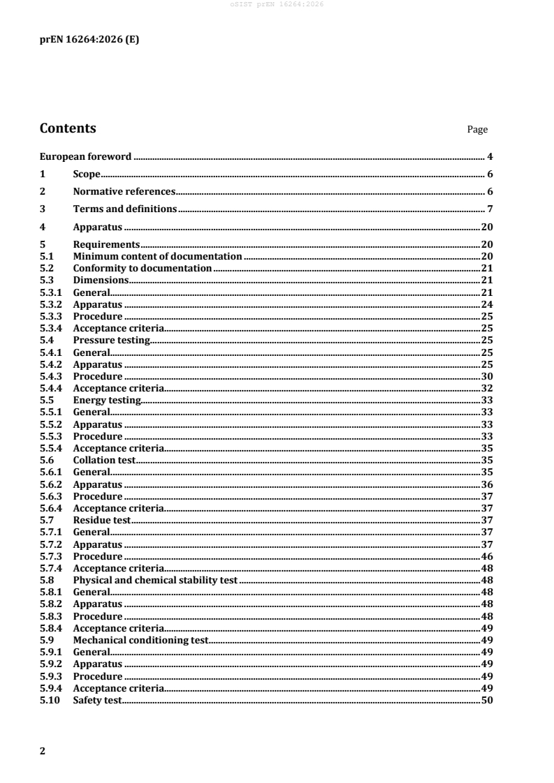
Contents Page
European foreword . 4
1 Scope . 6
2 Normative references . 6
3 Terms and definitions . 7
4 Apparatus . 20
5 Requirements . 20
5.1 Minimum content of documentation . 20
5.2 Conformity to documentation . 21
5.3 Dimensions. 21
5.3.1 General. 21
5.3.2 Apparatus . 24
5.3.3 Procedure . 25
5.3.4 Acceptance criteria. 25
5.4 Pressure testing . 25
5.4.1 General. 25
5.4.2 Apparatus . 25
5.4.3 Procedure . 30
5.4.4 Acceptance criteria. 32
5.5 Energy testing. 33
5.5.1 General. 33
5.5.2 Apparatus . 33
5.5.3 Procedure . 33
5.5.4 Acceptance criteria. 35
5.6 Collation test . 35
5.6.1 General. 35
5.6.2 Apparatus . 36
5.6.3 Procedure . 37
5.6.4 Acceptance criteria. 37
5.7 Residue test . 37
5.7.1 General. 37
5.7.2 Apparatus . 37
5.7.3 Procedure . 46
5.7.4 Acceptance criteria. 48
5.8 Physical and chemical stability test . 48
5.8.1 General. 48
5.8.2 Apparatus . 48
5.8.3 Procedure . 48
5.8.4 Acceptance criteria. 49
5.9 Mechanical conditioning test . 49
5.9.1 General. 49
5.9.2 Apparatus . 49
5.9.3 Procedure . 49
5.9.4 Acceptance criteria. 49
5.10 Safety test . 50
5.10.1 General . 50
5.10.2 Apparatus . 50
5.10.3 Firing unit . 51
5.10.4 Procedure . 53
5.10.5 Acceptance criteria . 53
5.11 Maximum content of lead in the primer mix . 54
5.11.1 General . 54
5.11.2 Procedure . 54
5.11.3 Acceptance criteria . 54
5.12 Safe disposal . 54
6 Categorization . 54
7 Minimum labelling . 55
7.1 Single cartridges . 55
7.1.1 General . 55
7.1.2 Marking of single cartridges . 55
7.2 Primary packs . 55
Annex A (normative) Testing of cartridges for powder actuated tools . 57
Annex B (informative) Mechanical conditioning test apparatus . 58
Annex C (normative) Graphical symbols . 61
Annex D (informative) Batch testing of cartridges for powder actuated tools . 63
Annex E (normative) Determination of lead in the primer mix of PAT cartridges . 65
Annex F (informative) Recommended energy ranges . 74
Annex ZA (informative) Relationship between this European Standard and the essential
requirements of Directive 2013/29/EU aimed to be covered . 76
Bibliography . 78
European foreword
This document (prEN 16264:2026) has been prepared by Technical Committee CEN/TC 212
“Pyrotechnic articles”, the secretariat of which is held by NEN.
This document is currently submitted to the CEN Enquiry.
This document will supersede EN 16264:2014.
In comparison with the previous edition, the following technical modifications have been made:
— the scope has been streamlined by deleting several obsolete cartridge calibres;
— Clause 2, the decisions of C.I.P. have been listed;
— Clause 3 have been updated. the definition for the energy developed by a cartridge and indicated by
colour marking has been harmonized across the document to “energy level”;
— Clause 3, some definitions and symbols have been aligned with those in EN 15895:2025,
prEN 16263:2026 [2], and the definitions of C.I.P.;
— Clause 3, the figures have been aligned with those of EN 15895:2025 or modernised;
— 5.4.2.6 and in 5.4.3.5, the description of the procedure for pressure measurement has been improved;
— 5.4.3.5, the use of grease in pressure measurement has been deleted in accordance with the
amendments adopted by C.I.P. in 2023;
— 5.6.4, the wording has been corrected to clearly indicated the combined requirements for passing the
test;
— 5.7.2, several design drawings have been completed by adding the necessary dimensional tolerances;
— 5.7.3, the prescribed test temperature and humidity ranges have been aligned with those of C.I.P.;
— 5.7.3, the number of test sequences in the residue test have been reduced from three to two;
— 5.7.3, the test procedure has been streamlined to better represent test rigs of different designs;
— 5.8, the test procedures for the high and low temperature stability tests have been redefined;
— the formerly prescribed high temperature pressure test has been deleted;
— 5.11, limit values for the content of lead have been defined for two classes of PAT cartridges, lead-
free and leaded;
— 5.12, safe disposal has been added;
— 7.2, the labelling requirements have been streamlined to those not already listed in the Directive;
— Annex C, the symbols used in labelling have been aligned with EN ISO 7010:2020;
— Annex D, batch testing of cartridges for powder actuated tools has been added;
— Annex E, analysis methods for the determination of the content of lead have been added;
— Annex F, recommended energy ranges has been added;
— Annex ZA has been revised.
NOTE Words in italics (apart from document titles) are defined in Clause 3.
This document has been prepared under a standardization request addressed to CEN by the European
Commission. The Standing Committee of the EFTA States subsequently approves these requests for its
Member States.
For relationship with EU Legislation, see informative Annex ZA, which is an integral part of this document.
1 Scope
This document defines the procedures for classifying, testing and labelling of cartridges for powder
actuated tools (PAT cartridges), as defined in Clause 3 of this document.
This document applies to PAT cartridges which are all classified as P1.
This document does not apply to pyrotechnic articles containing blasting agents and military explosives
except black powder and flash composition.
PAT cartridges contain pyrotechnic composition(s) delivering mainly gases, intended to propel a piston.
The piston propels fasteners (e.g. nails) or drives hard marking characters into appropriate materials.
This document also applies to PAT cartridges sold to persons younger than 18 years, if this is permitted
by the Member State due to the low hazard of the PAT cartridges.
NOTE PAT cartridges can also be used for hard marking tools. Information on cartridge operated fixing and
hard marking tools can be found in EN 15895:2025 [1].
This document applies to the cartridges listed in Table 1.
Table 1 — Lists of the established calibres for PAT cartridges
Type Calibre
Rimfire 5,5/16 (22 NC)
5,6/16 (22)
6,3/10
6,3/12
6,3/16
6,8/11
6,8/18
Centrefire 9 × 17 W
2 Normative references
The following documents are referred to in the text in such a way that some or all of their content
constitutes requirements of this document. For dated references, only the edition cited applies. For
undated references, the latest edition of the referenced document (including any amendments) applies.
EN 15895:2025, Powder actuated hand-held fixing and hard marking tools — Safety requirements
EN ISO 3611:2023, Geometrical product specifications (GPS) — Dimensional measuring equipment —
Design and metrological characteristics of micrometers for external measurements (ISO 3611:2023)
EN ISO 9237:1995, Textiles — Determination of permeability of fabrics to air (ISO 9237:1995)
EN ISO 13385-1:2019, Geometrical product specifications (GPS) — Dimensional measuring equipment —
Part 1: Design and metrological characteristics of callipers (ISO 13385-1:2019)
EN ISO 7010:2020, Graphical symbols — Safety colours and safety signs — Registered safety signs
(ISO 7010:2019)
ISO 22863-3:2020, Fireworks — Test methods for determination of specific chemical substances — Part 3:
Lead and lead compounds by atomic absorption
ISO 22863-5:2021, Fireworks — Test methods for determination of specific chemical substances — Part 5:
Analysis of lead and lead compounds by inductively coupled plasma spectrometry (ICP)
3 Terms and definitions
For the purposes of this document, the following terms and definitions apply.
ISO and IEC maintain terminology databases for use in standardization at the following addresses:
— ISO Online browsing platform: available at https://www.iso.org/obp/
— IEC Electropedia: available at https://www.electropedia.org/
3.1
acceptance quality limit
AQL
quality level that is the worst tolerable process average when a continuing series of lots is submitted for
acceptance sampling
3.2
base material
material into which the fastener or marking punch is driven
3.3
calibre
designation of a cartridge, normally expressed in the form “body diameter / length”
Note 1 to entry: See Scope for applicable cartridge calibres.
3.4
cartridge
device which contains a minor quantity of primer mix and a larger quantity of solid propellant used to
drive the piston of a fixing or hard marking tool
Note 1 to entry: See Figure 1.
As impacted by EN ISO 7010:2020/A1:2020, EN ISO 7010:2020/A2:2022, EN ISO 7010:2020/A3:2022,
EN ISO 7010:2020/A4:2023 EN ISO 7010:2020/A5:2023, EN ISO 7010:2020/A6:2023,
EN ISO 7010:2020/A7:2024, EN ISO 7010:2020/A8:2024, EN ISO 7010:2020/A9:2025
Figure 1 — Cartridge (example: calibre 6,8/11; external view and section)
3.5
single cartridge
loose cartridge
cartridge that is not mechanically attached to other cartridges and is inserted individually in the cartridge
chamber (by hand)
3.6
collated cartridge
cartridge that is contained with a number of others in a means of collation, e.g. a plastic collation strip or
a metal disc
3.7
cartridge chamber
essentially cylindrical or slightly conical bore which accommodates the cartridge before ignition; located
in the rear end of the piston guide of a cartridge operated tool; the dimensions of the cartridge chamber
correspond to cartridge calibre
3.8
powder actuated tool
PAT
tool with a piston powered by the hot combustion gases from a cartridge and comprising powder actuated
fixing and hard marking tools
[SOURCE: EN 15895:2025, 3.1]
3.9
cartridge case
closed container of essentially cylindrical shape made of metal or plastic forming the outer shell of a
cartridge and containing a primer or primer mix and propellant
3.10
cartridge type
set of cartridges defined by specific calibre and design, including pyrotechnic compositions and tolerances
3.11
centrefire cartridge
cartridge in which the primer is located in a primer cup (see 3.26)
3.12
coefficient of tolerance
coefficients of tolerance for n measurements with a statistical certainty of 95 % in K 90 % of cases,
3,n
where K = 2,36 for n=10
3,10
3.13
collation
means for attaching several cartridges to each other at regular distances
Note 1 to entry: Plastic strips and metal discs are commonly used for collation
3.14
combustion chamber
cavity adjoining to the cartridge chamber in which the combustion of the propellant takes place and
consisting of a bore connecting the cartridge chamber with the main cavity of piston guide, the free volume
of the piston guide itself behind the piston in its rearmost position, and sometimes a free volume in the
concave piston head
3.15
crimp
closed front end of a (metal) cartridge generated by radial deformation of the cylindrical body into tight
folds with an essentially star-shaped cross section
3.16
fastener
object intended for use in a cartridge operated fixing tool
Note 1 to entry: The object can be a nail, a threaded stud or similar object that is driven into the base material.
3.17
ignition pin
steel pin guided in a bore in the breech face igniting the primer mix of the cartridge by impacting on the
rim of the cartridge bottom or centre primer cup
3.18
lot
batch of cartridges of the same type, having homogeneous components, manufactured in series
production
3.19
piston
essentially cylindrical or shouldered element made of annealed steel, freely movable longitudinally in the
cylindrical piston guide (“barrel”) of a cartridge operated tool which is accelerated by the high pressure
in the combustion chamber at its rear and impacts on the fastener or marking head with its tip
3.20
piston guide
“barrel” of a cartridge operated tool which is essentially the cylindrical bore of a tool and containing the
piston
3.21
plunger
slug
brass or semi hardened steel cylinder used in pressure barrel, having different face dimensions to
reproduce the additional volume (V ), the equivalent to the minimum operational volume of the
a
combustion chamber in a tool
Note 1 to entry “Slug” is used as a synonym of “plunger” in the context of pressure measurement with a test
barrel.
3.22
primary pack
package of cartridges of the same calibre and energy (colour), offered for retail sale as a single unit
3.23
primer
cap containing pyrotechnic composition(s) for ignition, designed to ignite the propellant in a centrefire
cartridge case
3.24
primer mix
pyrotechnic composition located in the rim of the cartridge or in the centre primer which ignites the
propellant when the ignition pin deforms the rim of the cartridge or the centre primer cup and locally
compresses and ignites the primer mix
3.25
propellant
mostly nitrocellulose-based powder which fills the cartridge partly or totally, depending on cartridge
energy, the hot combustion gases of which accelerate the piston of a cartridge operated tool
3.26
pyrotechnic composition
explosive substance or mixture of explosive substances which is designed, on ignition or initiation, to
produce heat, light, sound, gas or smoke or a combination of such effects through self-sustained
exothermic chemical reactions
3.27
rim
circumferential outward bulge at the rear end of a cartridge generated by axial deformation of the
hemispherical end of the punch-drawn metal blank
3.28
rimfire cartridge
cartridge in which the primer mix is located in the rim of the cartridge case
3.29
test barrel
test equipment used to measure the gas pressure and energy of PAT cartridges
3.30
minimum volume
V
ET
volume of the smallest technically possible cartridge chamber for a given calibre and maximum length of
the open cartridge (L )
Note 1 to entry: See Figure 2.
a) minimum volume of the cartridge chamber (V )
ET
(tool for single cartridges)
b) minimum volume of the cartridge chamber (V )
ET
(tool for cartridges collated in disks)
c) minimum volume of the cartridge chamber (V )
ET
(tool for cartridges collated in strips)
Key
1 minimum volume of the cartridge chamber (V )
ET
L maximum length of the open cartridge
NOTE V and L are constant values for each calibre and are laid down in Table 2 and Table 3.
ET 3
Figure 2 — Minimum volume of the cartridge chamber (V )
ET
3.31
total volume
V
C
total volume of maximum cartridge as presented in Figure 3 in accordance with Table 2
Figure 3 — V
C
3.32
volume of the material of the case
V
m
volume of the material of the case (without primer mix where rimfire cartridges are concerned, with
primer where centrefire cartridges are concerned) as presented in Figure 4
Figure 4 — V
m
3.33
additional volume
V
a
volume consisting of the volume of the combustion chamber with the piston in its extreme top position
and the open volume in the piston head, if any
Note 1 to entry: See Figure 5.
a) Additional volume (V ) (tool for single cartridges)
a
(see Table 2 for L )
b) Additional volume (V ) (tool for cartridges collated in disks)
a
(see Table 2 for L )
c) Additional volume (V ) (tool for cartridges collated in strips)
a
(see Table 2 for L )
Key
1 additional volume (V )
a
L maximum length of the open cartridge
Figure 5 — Additional volume (V )
a
3.34
total volume
V
tot
sum of the volumes of the combustion chamber and the empty cartridge chamber as
determined from the design drawings or CAD models
Note 1 to entry: See Figure 6.
a) total volume (V ) (tool for single cartridges)
tot
b) total volume (V ) (tool for cartridges collated in disks)
tot
c) total volume (V ) (tool for cartridges collated in strips)
tot
Key
1 total volume Vtot
NOTE Vtot is a design-specific value.
Figure 6 — Total volume (V )
tot
3.35
reduced volume
*
V
h
volume of the minimum size cartridge chamber V minus the volumes of the
ET
cartridge casing V and the propellant
m
Note 1 to entry: See Figure 7.
*
a) reduced volume of the cartridge chamber V (tool for single cartridges)
h
(see Table 2 for L )
*
b) reduced volume of the cartridge chamber V (tool for cartridges collated in disks)
h
(see Table 2 for L )
*
c) reduced volume of the cartridge chamber V (tool for cartridges collated in strips)
h
(see Table 2 for L )
Key
*
1 reduced volume of the cartridge chamber V
h
(L3) maximum length of the open cartridge
NOTE 1 Shaded area inside the cartridge denotes empty space between grains of propellant.
*
NOTE 2 V is a constant value for a given calibre in accordance with Table 9.
h
*
Figure 7 — Reduced volume of the cartridge chamber V
h
3.36
reduced system testing volume
V
S
reduced volume of the combustion chamber for performing the collation test with
an overpressure of 1,10 or 1,15 times of the maximum gas pressure p , depending on the test
max
Note 1 to entry: To achieve an overpressure of 1,10 times, VS is calculated according to the following formula (see
5.6.2.2):
1b/ 1b/*
VV1,,10⋅+ 1 10−⋅1 V
( )
Sa h
Note 2 to entry: To achieve an overpressure of 1,15 times, V is calculated according to the following formula (see
S
5.6.2.3):
1 1
*
bb
VV1,,15⋅+ 1 15−⋅1 V
Sa h
*
Note 3 to entry: The values of b and V per calibre, as given in Table 9, apply.
h
Note 4 to entry: For powder actuated tools for single and for collated cartridges, see Figure 8 below.
a) reduced system testing volume of the combustion chamber V
S
(tool for single cartridges)
=
=
b) reduced system testing volume of the combustion chamber V
S
(tool for cartridges collated in disks)
c) reduced system testing volume of the combustion chamber V
S
(tool for cartridges collated in strips)
Key
1 reduced system testing volume VS
L3 maximum length of the open cartridge
NOTE V < V
S a
Figure 8 — Reduced system testing volume of the combustion chamber V
S
3.37
energy level
range of kinetic energies measured in Joules as defined in Table 13, identified by a number and a colour
4 Apparatus
The standard equipment described in Clause 4 shall be used during the test. Any equivalent equipment
with the same or better accuracy may be used as an alternative.
4.1 Timing device.
— Type 1: Timing device capable of being read to the nearest 0,01 s.
— Type 2: Timing device capable of being read to the nearest 1 min.
4.2 Calliper.
— Type 1: Flat faced Vernier calliper reading to 0,05 mm which shall be in accordance
with EN ISO 13385-1:2019 (see 3.4).
— Type 2: Micrometer calliper reading to 0,01 mm which shall be in accordance with EN ISO 3611:2023
(see 3.4 and 4.4) .
4.3 Scale.
— Type 1: Minimum capacity 200 g.
— Type 2: Resolution 1,0 mg or better (linearity e = 1,0 mg or better).
4.4 Climatic chamber.
— Temperature from (– 10 ± 1) °C up to (52 ± 1) °C.
— Relative humidity from (60 ± 5) % up to (75 ± 5) %.
Several climatic chambers may be used for different tests if these tests require different temperatures or
humidity.
5 Requirements
5.1 Minimum content of documentation
The documentation shall contain the following minimum information:
— identification and description of the cartridges (name and calibre);
— identification of the fixing or hard marking tool(s) for which the conformity certificate of the
cartridges is applied;
— net weight of propellant;
— net weight of primer mix;
— chemical composition and percentage of substances used in the propellant and in the primer mix;
— pressure developed by the cartridges, measured as defined in 5.4;
— energy level of the cartridges as defined in 5.5;
— colour codes used to compare cartridges according to their energy level in the product range;
— name and address of the manufacturer or importer.
5.2 Conformity to documentation
The tested cartridges shall be in accordance with the relevant manufacturing documentation. The
requirement is considered fulfilled if the manufacturing documentation contains the minimum content
(see 5.1) and the article has been successfully tested as described in 5.3 and 5.5.
Neither quantitative nor qualitative analyses of the chemical composition shall be required.
5.3 Dimensions
5.3.1 General
The verification of dimensions shall be done to check the important cartridge dimensions from the safety
point of view (see Figure 9, Figure 10 and Table 2).
a)
b)
Figure 9 — Dimensions of rimfire type cartridges
Figure 10 — Dimensions of centre-fire type cartridges
Table 2 — Maximum cartridges dimensions (Dimensions in millimetres and volumes in cubic centimetres)
CARTRIDGE L L R R f β P P α S H H V
3 6 1 1 2 1 2 C
5,5/16
15,6 15,3 1,12 7,06 5,74 5,74 17°32′44” 27,64 5,49 5,49 0,39
(22 NC)
5,6/16 (22) 16,2 15,5 1,12 7,06 5,74 5,74 0,35
6,3/10 10,8 10,3 1,25 7,6 6,32 6,32 0,26
Rimfire
type 6,3/12 12,8 12,5 1,3 7,6 6,32 6,32 0,33
6,3/16 16,6 16,3 1,3 7,6 6,32 6,32 0,5
6,8/11 11,8 11 1,45 8,5 6,86 6,86 0,34
6,8/18 18,7 18 1,45 8,5 6,86 6,86 0,61
Centrefire
9 × 17 W 18,3 18,15 1,35 11,1 0,3 45° 9,58 9,58 1,08
type
Key
L max. length of open cartridge β chamfer angle H max. collar diameter 1
3 1
L max. length of closed cartridge P max. case diameter near rim H max. collar diameter 2
6 1 2
R max. rim height P max. case diameter near cone V Total volume of maximum cartridge
2 C
R max. head diameter α neck angle
f chamfer height S height of junction cone
5.3.2 Apparatus
The shape gauge used in this test is a block of steel with a shaped bore as illustrated in Figure 11 with
dimensions given in Table 3.
Figure 11 — Chamber dimensions
Table 3 — Minimum chamber dimensions (Dimensions in millimetres and volumes in cubic
centimetres)
CARTRIDGE L R R P H G V
3 1 1 2 1 ET
5,5/16 (22 NC) 16 1,1 7,1 5,8 5,76 6 0,45
5,6/16 (22) 16,33 1,1 7,3 5,76 5,76 6 0,44
6,3/10 11 1,25 7,7 6,35 6,35 6 0,37
6,3/12 13 1,25 7,7 6,35 6,35 6 0,43
Rimfire type
6,3/16 17 1,25 7,7 6,35 6,35 6 0,56
6,8/11 12 1,45 8,55 6,9 6,9 6 0,48
6,8/18 19 1,45 8,55 6,9 6,9 6 0,74
Centrefire type 9 × 17 W 18,5 1,3 11,2 9,6 9,6 6 1,37
Key
G Free diameter
V Minimum volume of the cartridge chamber
ET
NOTE Other symbols are defined in the key of Table 2.
5.3.3 Procedure
The dimensions of the cartridge shall be checked. Fixed dimension limits are checked by means of a
general shape gauge, taking into account minimum dimensions of chambers as referred in Figure 11
and Table 3.
The cartridges shall be fitted in the general shape gauge and the dimensions L , H verified with
6 2
micrometer calliper (4.2).
5.3.4 Acceptance criteria
The maximum dimensions, verified with micrometer calliper (4.2), shall be in conformity with the fixed
dimension limits reported in Figures 9 and 10 and in Table 2.
All cartridges tested shall enter smoothly into the gauge with a maximum force of 10 N.
5.4 Pressure testing
5.4.1 General
The purpose of this test is to verify the maximum gas pressure developed by the tested cartridges.
5.4.2 Apparatus
The apparatus shown in Figures 12 to 17 shall be used for pressure testing. The dimensions reported on
the drawings shall be in accordance with the tolerances specified in Table 4.
Table 4 — Apparatus tolerance
Dimension Tolerance
P
+ 0,03 mm
H
R
+ 0,05 mm
R
L + 0,10 mm
5.4.2.1 Test barrel assembly, made from steel with a minimum tensile strength of R = 1 000 MPa.
m
NOTE Suitable material is, e.g. no. 1.7225 (42CrMo4).
Key
1 barrel and transducer mounting
2 piezoelectric pressure transducer
3 cartridge holder
4 plunger
Figure 12 — Test barrel assembly
5.4.2.2 Plunger operated test barrel, made from steel with a minimum tensile strength
of R = 1 000 MPa.
m
NOTE Suitable material is no. 1.7225 (42CrMo4). The dimensions in brackets are given for information.
Figure 13 — Plunger operated test barrel
5.4.2.3 Cartridge holder, made from steel with a minimum tensile yield strength of R = 1 300 MPa
m
(see Table 5).
NOTE Suitable materials are no. 1.7707 (30CrMoV9) or no. 1.6580 (30CrNiMo8).
Dimensions in millimetres
Figure 14 — Cartridge holder
Dimensions in millimetres
Table 5 — Cartridge holder
CARTRIDGE L R R P H
3 1 1 2
5,5/16 (22 NC) 16 1,1 7,10 5,80 5,76
5,6/16 (22) 16,33 1,1 7,30 5,76 5,76
6,3/10 11 1,25 7,70 6,35 6,35
6,3/12 13 1,25 7,70 6,35 6,35
6,3/16 17 1,25 7,70 6,35 6,35
6,8/11 12 1,45 8,55 6,90 6,90
6,8/18 19 1,45 8,55 6,90 6,90
9 × 17 W 18,5 1,3 11,2 9,60 9,60
NOTE Symbols are defined in the key of Table 2.
5.4.2.4 Plunger, made from steel with a minimum tensile strength of R = 550 MPa (see Figure 15
m
and Table 6).
NOTE Suitable materials are brass (58 - 70 % Cu) or semi hardened steel with the following dimensions:
— diameter D : 16 mm (h7);
p
— mass Mp: (80 ± 1) g;
3 3
— additional volume Va: 0,16 cm to 0,80 cm ;
— length L: (proportional to mass).
Dimensions in millimetres
Figure 15 — Plunger (slug)
Table 6 — Plunger (slug)
V T
a
Test
cm mm
+0,02
Rimfire 0,16 1,00
+0,05
Centrefire 0,40 2,50
+0,05
Rimfire 0,80 5,00
The plunger shall be positioned such that one of its milled slots lines up with the axis of the transducer
bore (see Figure 16).
Dimensions in millimetres
a) Position of the crossed slots
b) Position of the crossed slots (cross section B-B) and position of the firing pin (from below;
view A)
Key
A top view
B-B cross section
Figure 16 — Plunger orientation
5.4.2.5 Seals, with dimensions in accordance with Figure 17.
NOTE Suitable material is CuZn40Pb2.
Dimensions in millimetres
Figure 17 — Seals
5.4.2.6 Electromechanical transducer, with the following characteristics:
a) Range of measurement: up to 7 000 bar;
b) Pressure transmission surface: Ø ≤ 6 mm;
c) Fundamental frequency: ≥ 100 kHz;
d) Deviation from linearity: ≤ 1 %;
5.4.2.7 Electronic filter, of approximately 20 kHz (−3 db) and Bessel characteristic n = 2
(12 dB/octave).
5.4.2.8 Climatic chamber (see 4.4).
5.4.2.9 Timing device type 2 (see 4.1).
5.4.3 Procedure
5.4.3.1 General
The test shall be carried out on cartridges acclimatized for at least 24 h, in a climatic chamber, at the
following conditions:
— temperature: (+21 ± 1) °C;
— relative humidity: (60 ± 5) %.
5.4.3.2 Rimfire
In case of rimfire cartridges, the pressure shall be measured using at least 12 cartridges for each
additional volume:
3 3
V = 0,16 cm and 0,80 cm
a
5.4.3.3 Centrefire
In case of centrefire cartridges, the pressure shall be measured using at least 12 cartridges for an
additional volume:
V = 0,40 cm
a
5.4.3.4 Evaluation of the results
Twelve firings shall be carried out for each additional volume in order to obtain 10 usable results.
To assess if the highest or lowest recorded pressure values are outliers, the following criterion shall be
applied:
— on completing a series of 12 measurements with the same additional volume, the recorded pressure
values shall be numbered in ascending order (p , … p );
1 12
— the extreme pressure values p and p shall be identified;
1 12
— the ratios ZB and ZB shall be calculated:
1 2
pp−
3 1
ZB =
pp−
11 1
and
pp−
12 10
ZB =
pp−
12 2
where
ZB and ZB are the ratios of differences of pressure values.
1 2
If ZB or ZB > 0,490, p or p respectively shall be eliminated.
1 2 1 12
If neither value is eliminated, the last two recorded values shall be disregarded.
If only one value is eliminated, the last recorded value shall be disregarded.
5.4.3.5 Sequence of testing steps
The test shall be conducted as indicated below:
a) The testing cartridges shall be acclimatized for at least 24 h at an ambient temperature of (+21 ± 1) °C
and at relative air humidity of (60 ± 5) %.
b) The cartridge holder and the appropriate plunger for the additional volume shall be selected
according to the calibre of the cartridge to be fired.
c) The bore of the barrel shall be cleaned and lightly lubricated such that the plunger slides in easily.
d) The electromechanical transducer shall be screwed onto the transducer holder, applying the
tightening torque specified in the technical documentation of the transducer.
e) The plunger shall be pushed in such that it contacts the cartridge chamber, with its flanges positioned
opposite to the cartridge so that one of the milled slots lines up with the axis of the transducer bore
(see Figure 16 b)).
f) In subsequent firings, care shall be taken that during handling the plunger is not moved – not even
slightly – out of position.
g) After each firing, the cartridge case shall be ejected and recovered to examine the marks from the
firings. If any penetration of the firing pin is detected, the firing pin shall be checked and exchanged
if found defective.
h) The plunger shall be recovered and checked to ensure that there are no marks from the firings.
i) Any carbon deposits shall be removed.
If there are signs of excessive gas leaks, the measurement obtained shall not be used. In subsequent tests,
the necessary precautions shall be taken to improve gas tightness.
5.4.4 Acceptance criteria
The results shall be interpreted in accordance with the rules of statistics as described in Table 7.
Table 7 — Acceptance criteria to be considered
Maximum admissible pressure for rimfire cartridges with additional
p (0,16)
...