


ISO 23414:2026
(Main)Oil and gas industries including lower carbon energy — Workover rigs for offshore fixed platforms
General Information
- Abstract
This document gives requirements for the design, fabrication, installation, commissioning and integrity management of workover rigs on offshore fixed platforms. This document is not applicable to workover equipment: installed on mobile or floating offshore units; intended for onshore use; coiled tubing unit or snubbing unit.
- Status
- Published
- Publication Date
- 08-Sep-2026
- Technical Committee
- ISO/TC 67/SC 4 - Drilling and production equipment
- Drafting Committee
- ISO/TC 67/SC 4 - Drilling and production equipment
- Current Stage
- 6060 - International Standard published
- Start Date
- 09-Sep-2026
- Due Date
- 25-Jun-2027
- Completion Date
- 09-Sep-2026
Buy Documents

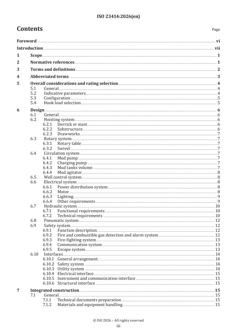
ISO 23414:2026 - Oil and gas industries including lower carbon energy — Workover rigs for offshore fixed platforms

ISO 23414:2026 - Industries du pétrole et du gaz, y compris les énergies à faible teneur en carbone — Appareils de reconditionnement pour plates-formes fixes en mer
Overview
ISO 23414:2026 sets out internationally recognized requirements for the design, fabrication, installation, commissioning, and integrity management of workover rigs used on offshore fixed platforms in the oil and gas industry, including lower carbon energy sectors. This standard does not cover workover equipment installed on mobile or floating offshore units, equipment intended for onshore use, or coiled tubing and snubbing units.
Complying with ISO 23414:2026 helps ensure that workover operations on fixed offshore platforms are safe, reliable, and environmentally responsible, while also facilitating effective integrity management throughout the rig’s lifecycle.
Key Topics
ISO 23414:2026 covers several important areas relevant to workover rigs for offshore fixed platforms:
- Design: Requirements related to equipment selection, key parameter calculations (such as hook load and substructure clearance height), system configuration, and the interface between subsystems.
- Fabrication: Guidelines for construction of rig structures, handling of workover equipment, welding standards, and prefabrication of piping.
- Installation and Commissioning: Procedures for both onshore and offshore installation phases, including inspection, loadout, transportation, hook-up, and system commissioning.
- Integrity Management: Maintenance planning, inspection regimes (annual, periodic, temporary), and documentation management to ensure ongoing rig performance and safety.
- System Integration: Mechanical, electrical, hydraulic, pneumatic, safety, and communication systems integration are addressed.
- Health, Safety, and Environment (HSE): Incorporates fire and gas detection, emergency escape, and fire-fighting systems for risk mitigation.
- Supporting Documentation: Recordkeeping for activities such as pressure testing, loadout design, commissioning, and inspections.
Applications
Implementing ISO 23414:2026 has significant practical value for organizations engaged in offshore oil and gas operations:
- Design and Engineering: Ensures technical specifications, safety requirements, and design methods are harmonized across projects and regions.
- Regulatory Compliance: Aids in meeting global and local regulatory requirements for offshore rig safety, construction, and environmental protection.
- Operations and Maintenance: Provides a complete framework for routine and preventive maintenance, inspections, and repair protocols, enhancing equipment longevity and operational uptime.
- Project Management: Supports project teams in ensuring smooth transitions between construction, installation, commissioning, and operational phases.
- Integrity and Risk Management: Guides operators in the systematic management of asset integrity, reducing downtime and risks associated with offshore workover operations.
- Sustainability: Addresses lower carbon energy requirements by encompassing relevant practices and considerations for greener operations.
Related Standards
ISO 23414:2026 is designed to align and integrate with several related international and industry standards, including but not limited to:
- ISO 4413 / ISO 4414 - Hydraulic and pneumatic safety and system requirements
- ISO 13535 / ISO 13626 / ISO 18647 - Drilling and well-servicing structures and equipment
- ISO 13702 / ISO 13703 / ISO 19901-3 / ISO 19902 - Offshore structure safety and topside requirements
- API Spec 4F, 7K, 8C, 16A - Drilling and well servicing equipment
- API RP 4G, 9B, 500, 505 - Maintenance, inspection, and electrical classification
- ASME B31.3 - Process piping construction and safety
- IEC series (60034, 60079, 60085, 61508, 61892) - Electrical equipment, explosive atmospheres, and functional safety
- AWS D1.1/D1.1M - Structural welding code for steel
Referencing and implementing ISO 23414:2026 alongside these standards enhances technical consistency and overall operational safety in offshore oil and gas industry projects, supporting both traditional and lower-carbon energy initiatives.
Buy Documents
ISO 23414:2026 - Oil and gas industries including lower carbon energy — Workover rigs for offshore fixed platforms
ISO 23414:2026 - Industries du pétrole et du gaz, y compris les énergies à faible teneur en carbone — Appareils de reconditionnement pour plates-formes fixes en mer
Get Certified
Connect with accredited certification bodies for this standard

ABS Quality Evaluations Inc.
American Bureau of Shipping quality certification.

Element Materials Technology
Materials testing and product certification.

ABS Group Brazil
ABS Group certification services in Brazil.
Sponsored listings
Frequently Asked Questions
ISO 23414:2026 is a standard published by the International Organization for Standardization (ISO). Its full title is "Oil and gas industries including lower carbon energy — Workover rigs for offshore fixed platforms". This standard covers: This document gives requirements for the design, fabrication, installation, commissioning and integrity management of workover rigs on offshore fixed platforms. This document is not applicable to workover equipment: installed on mobile or floating offshore units; intended for onshore use; coiled tubing unit or snubbing unit.
This document gives requirements for the design, fabrication, installation, commissioning and integrity management of workover rigs on offshore fixed platforms. This document is not applicable to workover equipment: installed on mobile or floating offshore units; intended for onshore use; coiled tubing unit or snubbing unit.
ISO 23414:2026 is classified under the following ICS (International Classification for Standards) categories: 75.180.10 - Exploratory, drilling and extraction equipment. The ICS classification helps identify the subject area and facilitates finding related standards.
ISO 23414:2026 is available in PDF format for immediate download after purchase. The document can be added to your cart and obtained through the secure checkout process. Digital delivery ensures instant access to the complete standard document.
Standards Content (Sample)
International
Standard
ISO 23414
First edition
Oil and gas industries including
2026-09
lower carbon energy — Workover
rigs for offshore fixed platforms
Industries du pétrole et du gaz, y compris les énergies à faible
teneur en carbone — Appareils de reconditionnement pour
plates-formes fixes en mer
Reference number
© ISO 2026
All rights reserved. Unless otherwise specified, or required in the context of its implementation, no part of this publication may
be reproduced or utilized otherwise in any form or by any means, electronic or mechanical, including photocopying, or posting on
the internet or an intranet, without prior written permission. Permission can be requested from either ISO at the address below
or ISO’s member body in the country of the requester.
ISO copyright office
CP 401 • Ch. de Blandonnet 8
CH-1214 Vernier, Geneva
Phone: +41 22 749 01 11
Email: copyright@iso.org
Website: www.iso.org
Published in Switzerland
ii
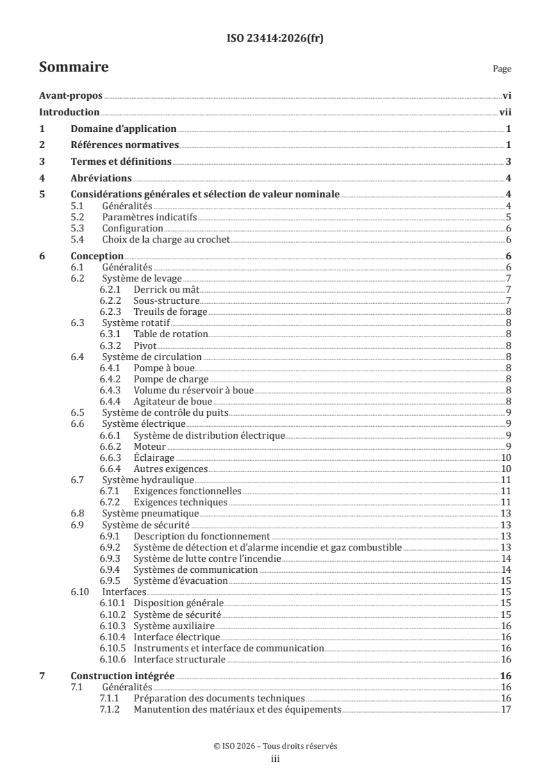
Contents Page
Foreword .vi
Introduction .vii
1 Scope . 1
2 Normative references . 1
3 Terms and definitions . 2
4 Abbreviated terms . 3
5 Overall considerations and rating selection . 4
5.1 General .4
5.2 Indicative parameters .4
5.3 Configuration .5
5.4 Hook load selection . .5
6 Design . 6
6.1 General .6
6.2 Hoisting system .6
6.2.1 Derrick or mast .6
6.2.2 Substructure .6
6.2.3 Drawworks .7
6.3 Rotary system .7
6.3.1 Rotary table .7
6.3.2 Swivel .7
6.4 Circulation system .7
6.4.1 Mud pump .7
6.4.2 Charging pump . . .7
6.4.3 Mud tanks volume .7
6.4.4 Mud agitator .8
6.5 Well control system .8
6.6 Electrical system .8
6.6.1 Power distribution system .8
6.6.2 Motor . .8
6.6.3 Lighting .9
6.6.4 Other requirements .9
6.7 Hydraulic system .10
6.7.1 Functional requirements .10
6.7.2 Technical requirements .10
6.8 Pneumatic system . 12
6.9 Safety system . 12
6.9.1 Function description . 12
6.9.2 Fire and combustible gas detection and alarm system . 12
6.9.3 Fire-fighting system . 13
6.9.4 Communication system . 13
6.9.5 Escape system . 13
6.10 Interfaces .14
6.10.1 General arrangement.14
6.10.2 Safety system .14
6.10.3 Utility system .14
6.10.4 Electrical interface . 15
6.10.5 Instrument and communication interface . 15
6.10.6 Structural interface . 15
7 Integrated construction .15
7.1 General . 15
7.1.1 Technical documents preparation . 15
7.1.2 Materials and equipment handling . 15
iii
7.1.3 Management and control of inspection reports .16
7.2 Structure construction .16
7.2.1 Prefabrication and assembly of structural steelwork .16
7.2.2 Integrated assembly .16
7.2.3 Welding .17
7.2.4 Welding inspection .18
7.3 Onshore equipment installation .19
7.3.1 General .19
7.3.2 Technical requirements .19
7.4 Pipeline prefabrication and installation .21
7.4.1 Pipeline prefabrication .21
7.4.2 Piping installation . 22
7.4.3 Pressure testing . 22
7.4.4 Piping flushing and cleaning . . 22
7.4.5 Flushing and cleaning flow rate . . 23
7.5 Corrosion . 23
7.5.1 Surface treatment . 23
7.5.2 Painting .24
8 Onshore commissioning .24
8.1 Commissioning scope .24
8.2 Commissioning preparation . 25
8.3 Commissioning . 25
8.3.1 General regulations . 25
8.3.2 Hoisting system equipment . 26
8.3.3 Rotary system equipment . 26
8.3.4 Circulation system equipment .27
8.3.5 Well control system equipment .27
8.3.6 Electrical system equipment .27
8.3.7 Hydraulic system equipment . . . 28
8.3.8 Fire and combustible gas detection and alarm system equipment . 28
8.3.9 Instrumentation and communication system equipment . 28
8.3.10 HVAC (heating ventilation and air conditioning) system equipment . 29
9 Offshore installation and commissioning .29
9.1 Weighing . 29
9.2 Loadout and transportation . 29
9.3 Offshore installation. 29
9.3.1 Pre-installation inspection . 29
9.3.2 Transportation and lifting . 30
9.3.3 Hoisting system and rotating system . 30
9.3.4 Circulating system .31
9.3.5 Well control system .31
9.3.6 Electrical system .31
9.3.7 Hydraulic system .31
9.3.8 Pneumatic system .32
9.3.9 Instrumentation and communication system .32
9.3.10 Safety system .32
9.3.11 Other auxiliary equipment and piping . 33
9.4 Offshore commissioning . 33
9.4.1 General . 33
9.4.2 Hoisting system . 33
9.4.3 Rotating system . 34
9.4.4 Circulating system . 34
9.4.5 Well control system . 34
9.4.6 Electrical system . 34
9.4.7 Hydraulic system . 34
9.4.8 Pneumatic system . 34
9.4.9 Instrumentation and communication system . 35
9.4.10 Safety system . 35
iv
9.4.11 Commissioning records and report requirements . 35
9.4.12 Integrated commissioning . 35
10 Maintenance and inspection .36
10.1 Maintenance . . 36
10.1.1 General . 36
10.1.2 Derrick or mast and substructure . 36
10.1.3 Hoisting system . 36
10.1.4 Well control system .37
10.1.5 Electrical system .37
10.1.6 Fire and gas detection system . 38
10.1.7 Maintenance during standby periods . . 39
10.2 Inspection . 39
10.2.1 General . 39
10.2.2 Documentation management . 39
10.2.3 Annual inspection . 39
10.2.4 Periodic inspection . . 39
10.2.5 Temporary inspection . 39
Annex A (informative) Additional information and guidance . 41
Annex B (informative) Piping pressure test record sheet . 51
Annex C (informative) Loadout and seafastening design documents .54
Annex D (informative) WOR commissioning outline .55
Annex E (informative) WOR inspection contents . 61
Bibliography .65
v
Foreword
ISO (the International Organization for Standardization) is a worldwide federation of national standards
bodies (ISO member bodies). The work of preparing International Standards is normally carried out through
ISO technical committees. Each member body interested in a subject for which a technical committee
has been established has the right to be represented on that committee. International organizations,
governmental and non-governmental, in liaison with ISO, also take part in the work. ISO collaborates closely
with the International Electrotechnical Commission (IEC) on all matters of electrotechnical standardization.
The procedures used to develop this document and those intended for its further maintenance are described
in the ISO/IEC Directives, Part 1. In particular, the different approval criteria needed for the different types
of ISO document should be noted. This document was drafted in accordance with the editorial rules of the
ISO/IEC Directives, Part 2 (see www.iso.org/directives).
ISO draws attention to the possibility that the implementation of this document may involve the use of (a)
patent(s). ISO takes no position concerning the evidence, validity or applicability of any claimed patent
rights in respect thereof. As of the date of publication of this document, ISO had not received notice of (a)
patent(s) which may be required to implement this document. However, implementers are cautioned that
this may not represent the latest information, which may be obtained from the patent database available at
www.iso.org/patents. ISO shall not be held responsible for identifying any or all such patent rights.
Any trade name used in this document is information given for the convenience of users and does not
constitute an endorsement.
For an explanation of the voluntary nature of standards, the meaning of ISO specific terms and expressions
related to conformity assessment, as well as information about ISO's adherence to the World Trade
Organization (WTO) principles in the Technical Barriers to Trade (TBT), see www.iso.org/iso/foreword.html.
This document was prepared by Technical Committee ISO/TC 67, Oil and gas industries including lower carbon
energy, Subcommittee SC 4, Drilling, production and injection equipment.
Any feedback or questions on this document should be directed to the user’s national standards body. A
complete listing of these bodies can be found at www.iso.org/members.html.
vi
Introduction
This document addresses the following aspects of workover rigs:
— design, including selection of equipment, calculation of key parameters, configuration of each system
and system interfaces;
— fabrication, including rig construction, handling of workover equipment and onshore prefabrication of
piping;
— commissioning, addressing commissioning preparation and requirements of each system;
— offshore installation, including loadout, transportation, hook up and offshore integrated commissioning;
— maintenance and inspection, defining maintenance requirements for each system and the requirements
of different inspection types.
Annex A provides additional information and guidance on the clauses of this document and is intended to be
read in conjunction with the main body of this document. The clause numbering in Annex A is the same as
that in the normative text to facilitate cross-referencing.
Annex B provides a record of the piping pressure test.
Annex C provides a list of loadout and fixation design documents.
Annex D provides a commissioning outline for workover rigs and an integrated commissioning outline for
workover rigs.
Annex E provides a typical in-service inspection plan for workover rigs.
vii
International Standard ISO 23414:2026(en)
Oil and gas industries including lower carbon energy —
Workover rigs for offshore fixed platforms
1 Scope
This document gives requirements for the design, fabrication, installation, commissioning and integrity
management of workover rigs on offshore fixed platforms.
This document is not applicable to workover equipment:
— installed on mobile or floating offshore units;
— intended for onshore use;
— coiled tubing unit or snubbing unit.
2 Normative references
The following documents are referred to in the text in such a way that some or all of their content constitutes
requirements of this document. For dated references, only the edition cited applies. For undated references,
the latest edition of the referenced document (including any amendments) applies.
ISO 3320, Fluid power systems and components — Cylinder bores and piston rod diameters and area ratios —
Metric series
ISO 4413, Hydraulic fluid power — General rules and safety requirements for systems and their components
ISO 4414, Pneumatic fluid power — General rules and safety requirements for systems and their components
ISO 4395, Fluid power systems and components — Cylinder piston rod end types and dimensions
ISO 7240-14, Fire detection and alarm systems — Part 14: Design, installation, commissioning and service of fire
detection and fire alarm systems in and around buildings
ISO 8501-1, Preparation of steel substrates before application of paints and related products — Visual
assessment of surface cleanliness — Part 1: Rust grades and preparation grades of uncoated steel substrates and
of steel substrates after overall removal of previous coatings
ISO 8503-1, Preparation of steel substrates before application of paints and related products — Surface
roughness characteristics of blast-cleaned steel substrates — Part 1: Specifications and definitions for ISO
surface profile comparators for the assessment of abrasive blast-cleaned surfaces
ISO 8504, Preparation of steel substrates before application of paints and related products — Surface
preparation methods
ISO 12944, Paints and varnishes — Corrosion protection of steel structures by protective paint systems
ISO 13535, Petroleum and natural gas industries — Drilling and production equipment — Hoisting equipment
ISO 13626, Petroleum and natural gas industries — Drilling and production equipment — Drilling and well-
servicing structures
ISO 13702, Oil and gas industries — Control and mitigation of fires and explosions on offshore production
installations — Requirements and guidelines
ISO 13703, Petroleum and natural gas industries — Design and installation of piping systems on offshore
production platforms
ISO 17635, Non-destructive testing of welds — General rules for metallic materials
ISO 18647, Petroleum and natural gas industries — Modular drilling rigs for offshore fixed platforms
ISO 19901-3, Oil and gas industries including lower carbon energy — Specific requirements for offshore
structures — Part 3: Topsides structure
ISO 19902, Petroleum and natural gas industries — Fixed steel offshore structures
IEC 60034-11, Rotating electrical machines — Part 11: Thermal protection
IEC 60076-1, Power transformers — Part 1: General
IEC 60079-0, Explosive atmospheres — Part 0: Equipment — General requirements
IEC 60079-10-1, Explosive atmospheres — Part 10-1: Classification of areas — Explosive gas atmospheres
IEC 60079-14, Explosive atmospheres — Part 14: Electrical installation design, selection and installation of
equipment, including initial inspection
IEC 60079-17, Explosive atmospheres — Part 17: Electrical installations inspection and maintenance
IEC 60085, Electrical insulation — Thermal evaluation and designation
IEC 60092-3, Electrical installations in ships — Part 3: Cables (construction, testing and installations)
IEC 61508 (all parts), Functional safety of electrical/electronic/programmable electronic safety-related systems
IEC 61892-3, Mobile and fixed offshore units — Electrical installations — Part 3: Equipment
API Spec 4F, Specification for Drilling and Well Servicing Structures
API Spec 7K, Drilling and Well Servicing Equipment
API Spec 8C, Drilling and Production Hoisting Equipment
API Spec 16A, Specification for Drill-through Equipment
API Std 53, Well Control Equipment Systems for Drilling Wells
API Std 613, Special-purpose Gears for Petroleum, Chemical, and Gas Industry Services
API RP 4G, Operation, Inspection, Maintenance, and Repair of Drilling and Well Servicing Structures
API RP 9B, Application, Care, and Use of Wire Rope for Oil Field Service
API RP 500, Classification of Locations for Electrical Installations at Petroleum Facilities Classified as Class I,
Division 1, and Division 2
API RP 505, Recommended Practice for Classification of Locations for Electrical Installations at Petroleum
Facilities Classified as Zone 0, Zone 1, and Zone 2
ASME B31.3, Processing Piping
AWS D1.1/D1.1M, Structural Welding Code-Steel
3 Terms and definitions
For the purposes of this document, the following terms and definitions apply.
ISO and IEC maintain terminology databases for use in standardization at the following addresses:
— ISO Online browsing platform: available at https:// www .iso .org/ obp
— IEC Electropedia: available at https:// www .electropedia .org/
3.1
number of effective travelling lines
number of effective lines
number of lines of drilling line strung over the sheaves of the travelling block that are load-bearing
Note 1 to entry: In a standard block-and-tackle system, this number is twice the number of sheaves on the travelling
block.
Note 2 to entry: This number is used in conjunction with the dead line to calculate the total number of effective wire
lines and the fast line pull.
3.2
workover depth
maximum depth achievable during workover operations using a workover rig and 88,9 mm (3,5 in) drill
pipe, under the specified number of effective travelling lines (3.1) in the hoisting system
3.3
substructure clearance height
clearance height between the bottom surface of the drill floor and the upper deck of the topsides
3.4
maximum hook load
maximum load that the workover rig can lift using the hoisting system under the maximum number of lines
Note 1 to entry: The maximum load is determined by material strength and the specified safety factor.
Note 2 to entry: This load includes both static and dynamic forces.
3.5
piping and instrument diagram
schematic drawing that defines all mechanical and instrumentation components of a process flow, including
but not limited to piping, valves, equipment, instruments, and their interrelationships
4 Abbreviated terms
AC alternating current
BOP blowout preventer
CCTV closed circuit television
DC direct current
HRC Rockwell hardness test rating
MCC motor control centre
NDT non-destructive test
OEM original equipment manufacturer
PA/GA public address system/gas alarm system
PLC programmable logic controller
PMS planned maintenance system
UPS uninterruptible power supply
VFD variable-frequency drive
WOR workover rig
WPQR welding procedure qualification record
WPS welding procedure specification
5 Overall considerations and rating selection
5.1 General
5.1.1 Workover rigs (WOR) can be classified according to the driving mode as follows:
— mechanical drive: the drawworks and rotary table are driven by diesel engines;
— electric drive: the drawworks and rotary table are driven by electric motors, which are divided into
direct current (DC) driven and alternating current (AC) driven;
— hydraulic drive: the drawworks and rotary table are driven by hydraulic motors;
— composite drive: the drawworks and rotary table adopt a combination of mechanical drive, electric
drive, and hydraulic drive.
5.1.2 The WOR should be able to perform workover operations safely, economically and reliably and
should be according to ISO 12100, ISO 13849, IEC 60812 and IEC 61882.
5.1.3 The WOR should employ a modular design and construction to facilitate installation, connection and
commissioning on the platform.
5.1.4 The WOR shall be verified to withstand the same operational, extreme and abnormal metocean and
seismic design situations applicable to the fixed offshore steel platform on which the WOR will be operating.
5.1.5 The WOR should be equipped with advanced automated control systems and automated wellhead
tools, such as automated elevators and automated slips, to reduce manual operations and enhance safety.
5.1.6 During WOR braking or drilling operations, an energy recovery system should be implemented to
convert excess energy into electrical energy for storage or reuse, thereby reducing energy waste. The design
and installation of the energy recovery system shall follow the OEM technical requirements.
5.1.7 Under the premise of ensuring the structural strength of the WOR, lightweight materials and designs
should be adopted to reduce the equipment's self-weight and to achieve lower energy consumption.
5.2 Indicative parameters
The indicative parameters for WOR are shown in Table 1.
Table 1 — Indicative parameters for WOR
b b
WOR rating 90 110 135 160 180 225
Workover depth
2 500 3 500 4 500 5 500 6 500 7 500
m
Maximum hook load
900 1 100 1 350 1 600 1 800 2 250
kN
a
Rating hook load
600 800 1 000 1 200 1 500 1 800
kN
Rated power of drawworks
260 to 330 280 to 400 330 to 450 400 to 500 450 to 600 550 to 746
kW
Rated power of mud pumps ≥ 261 ≥ 373 ≥ 373 ≥ 597 ≥ 597 ≥ 746
kW(hp) (≥ 350) (≥ 500 ) (≥ 500 ) (≥ 800 ) (≥ 800) (≥ 1 000)
Height of the mast
≥ 29 ≥ 31 ≥ 33
m
Opening diameter of rotary table
698,5 (27 1/2) to 952,5
444,5 (17 1/2) 520,7 (20 1/2)
(37 1/2)
mm (in)
Substructure clearance height
≥ 7,5
m
Number of effective trav-
6 to 8 8 to 10 10
elling lines
Drilling line diameter
26 to 29 29 to 32 32
Travelling
mm
system
Hoisting speed of the
hook with no load
≥1
m/s
Each well With full
position not rated 36 (70)
in working setback
Wind bearing
condition and
capacity
With
the mast is
47,8 (93)
out set-
erected
back
m/s (knot)
a
The data in this column (3 s gust wind speed at 10 m above sea level) should be determined from the metocean conditions of
the offshore site where the work over rig is located, and is the minimum recommended value.
b
Not suitable for use.
5.3 Configuration
The WOR shall include a power system, hoisting system, rotary system, circulation system, well control
system, hydraulic system, electrical system, pneumatic system, instrumentation and communication
system, safety system, skidding system. Other systems and facilities may exist as needed.
5.4 Hook load selection
5.4.1 The required hook load is the key parameter for WOR selection. The maximum value that can be
encountered in various conditions during workover operations shall be considered when calculating the
required hook load.
5.4.2 The maximum hook load of the selected WOR shall not be less than the hook load required for
workover operations. Based on the hook load required for workover operations, select a WOR in accordance
with Table 1, ensuring that the chosen rig's maximum hook load exceeds the required hook load.
NOTE A.5.4 gives recommended practice for calculating the hook load required for workover operations.
6 Design
6.1 General
6.1.1 The design of the WOR shall conform with the metocean design situation required for its operating
site, with reference to ISO 19901-3.
6.1.2 The WOR shall be designed to be anti-corrosive, moisture-resistant and salt-mist-resistant.
6.1.3 The WOR shall be capable of moving horizontally in any direction within the wellhead area of the
platform.
6.1.4 The center of the rotary table shall be able to align with any well slot.
6.1.5 The span of the skid rails shall be determined accounting for the platform configuration and well
slot layout.
6.1.6 The location of the driller's cabin shall enable the driller to observe the monkey board, the derrick or
mast gate and the rotary table area.
6.1.7 The driller's cabin shall include functions for controlling the drawworks, mud pump, rotary table
and other equipment.
6.1.8 Dropped object and automated equipment hazardous events shall be identified.
6.1.9 The causes and consequences of such events shall be identified using methodologies such as FMECA
(failure mode effects and criticality analysis) and HAZOP (hazard and operability).
6.1.10 Both the causes and the consequences shall be mitigated particularly with respect to life-safety.
6.2 Hoisting system
6.2.1 Derrick or mast
6.2.1.1 The derrick or mast design shall be in accordance with ISO 13626 and API Spec 4F.
6.2.1.2 The design parameters of the derrick or mast shall be in accordance with API Spec 4F.
6.2.1.3 The structural configuration of the derrick or mast should be telescopic or multi-section self-
lifting.
6.2.1.4 Hydraulic or rack and pinion hoisting rigs may be used.
6.2.1.5 The basic parameters of the derrick or mast shall be in accordance with Table 1.
6.2.2 Substructure
6.2.2.1 The substructure is divided into an upper substructur
...
Norme
internationale
ISO 23414
Première édition
Industries du pétrole et du gaz,
2026-09
y compris les énergies à faible
teneur en carbone — Appareils de
reconditionnement pour plates-
formes fixes en mer
Oil and gas industries including lower carbon energy —
Workover rigs for offshore fixed platforms
Numéro de référence
DOCUMENT PROTÉGÉ PAR COPYRIGHT
© ISO 2026
Tous droits réservés. Sauf prescription différente ou nécessité dans le contexte de sa mise en œuvre, aucune partie de cette
publication ne peut être reproduite ni utilisée sous quelque forme que ce soit et par aucun procédé, électronique ou mécanique,
y compris la photocopie, ou la diffusion sur l’internet ou sur un intranet, sans autorisation écrite préalable. Une autorisation peut
être demandée à l’ISO à l’adresse ci-après ou au comité membre de l’ISO dans le pays du demandeur.
ISO copyright office
Case postale 401 • Ch. de Blandonnet 8
CH-1214 Vernier, Genève
Tél.: +41 22 749 01 11
E-mail: copyright@iso.org
Web: www.iso.org
Publié en Suisse
ii
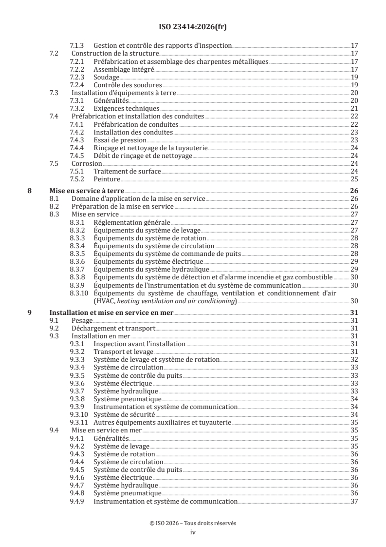
Sommaire Page
Avant-propos .vi
Introduction .vii
1 Domaine d’application . 1
2 Références normatives . 1
3 Termes et définitions . 3
4 Abréviations . 4
5 Considérations générales et sélection de valeur nominale . 4
5.1 Généralités .4
5.2 Paramètres indicatifs .5
5.3 Configuration .6
5.4 Choix de la charge au crochet .6
6 Conception . 6
6.1 Généralités .6
6.2 Système de levage .7
6.2.1 Derrick ou mât .7
6.2.2 Sous-structure . .7
6.2.3 Treuils de forage .8
6.3 Système rotatif .8
6.3.1 Table de rotation .8
6.3.2 Pivot .8
6.4 Système de circulation .8
6.4.1 Pompe à boue . .8
6.4.2 Pompe de charge .8
6.4.3 Volume du réservoir à boue .8
6.4.4 Agitateur de boue .8
6.5 Système de contrôle du puits .9
6.6 Système électrique .9
6.6.1 Système de distribution électrique .9
6.6.2 Moteur .9
6.6.3 Éclairage .10
6.6.4 Autres exigences .10
6.7 Système hydraulique .11
6.7.1 Exigences fonctionnelles .11
6.7.2 Exigences techniques .11
6.8 Système pneumatique . 13
6.9 Système de sécurité . 13
6.9.1 Description du fonctionnement . 13
6.9.2 Système de détection et d'alarme incendie et gaz combustible . 13
6.9.3 Système de lutte contre l’incendie .14
6.9.4 Systèmes de communication .14
6.9.5 Système d’évacuation . 15
6.10 Interfaces . 15
6.10.1 Disposition générale. 15
6.10.2 Système de sécurité . 15
6.10.3 Système auxiliaire .16
6.10.4 Interface électrique . .16
6.10.5 Instruments et interface de communication .16
6.10.6 Interface structurale .16
7 Construction intégrée . 16
7.1 Généralités .16
7.1.1 Préparation des documents techniques .16
7.1.2 Manutention des matériaux et des équipements.17
iii
7.1.3 Gestion et contrôle des rapports d’inspection .17
7.2 Construction de la structure .17
7.2.1 Préfabrication et assemblage des charpentes métalliques .17
7.2.2 Assemblage intégré .17
7.2.3 Soudage .19
7.2.4 Contrôle des soudures .19
7.3 Installation d'équipements à terre . 20
7.3.1 Généralités . 20
7.3.2 Exigences techniques .21
7.4 Préfabrication et installation des conduites . 22
7.4.1 Préfabrication de conduites . 22
7.4.2 Installation des conduites . 23
7.4.3 Essai de pression . 23
7.4.4 Rinçage et nettoyage de la tuyauterie .24
7.4.5 Débit de rinçage et de nettoyage .24
7.5 Corrosion .24
7.5.1 Traitement de surface .24
7.5.2 Peinture . 25
8 Mise en service à terre . .26
8.1 Domaine d'application de la mise en service . 26
8.2 Préparation de la mise en service . 26
8.3 Mise en service .27
8.3.1 Réglementation générale .27
8.3.2 Équipements du système de levage .27
8.3.3 Équipements du système de rotation . 28
8.3.4 Équipements du système de circulation . 28
8.3.5 Équipements du système de commande de puits . 28
8.3.6 Équipements du système électrique . 29
8.3.7 Équipements du système hydraulique . 29
8.3.8 Équipements du système de détection et d'alarme incendie et gaz combustible . 30
8.3.9 Équipements de l'instrumentation et du système de communication . 30
8.3.10 Équipements du système de chauffage, ventilation et conditionnement d'air
(HVAC, heating ventilation and air conditioning) . 30
9 Installation et mise en service en mer.31
9.1 Pesage .31
9.2 Déchargement et transport .31
9.3 Installation en mer .31
9.3.1 Inspection avant l’installation .31
9.3.2 Transport et levage .31
9.3.3 Système de levage et système de rotation .32
9.3.4 Système de circulation . 33
9.3.5 Système de contrôle du puits . 33
9.3.6 Système électrique . 33
9.3.7 Système hydraulique . 33
9.3.8 Système pneumatique . . 34
9.3.9 Instrumentation et système de communication . 34
9.3.10 Système de sécurité . 34
9.3.11 Autres équipements auxiliaires et tuyauterie . 35
9.4 Mise en service en mer . 35
9.4.1 Généralités . 35
9.4.2 Système de levage . . 35
9.4.3 Système de rotation . 36
9.4.4 Système de circulation . 36
9.4.5 Système de contrôle du puits . 36
9.4.6 Système électrique . 36
9.4.7 Système hydraulique . 36
9.4.8 Système pneumatique . . . 36
9.4.9 Instrumentation et système de communication .37
iv
9.4.10 Système de sécurité .37
9.4.11 Exigences en matière d'enregistrements et de rapports de mise en service .37
9.4.12 Mise en service intégrée .37
10 Maintenance et contrôle .38
10.1 Maintenance . . 38
10.1.1 Généralités . 38
10.1.2 Derrick ou mât et sous-structure . 38
10.1.3 Système de levage . 38
10.1.4 Système de contrôle du puits . 39
10.1.5 Système électrique . 39
10.1.6 Système de détection d’incendie et de gas .41
10.1.7 Entretien pendant les périodes d’inactivité .41
10.2 Inspection .41
10.2.1 Généralités .41
10.2.2 Gestion de la documentation .41
10.2.3 Inspection annuelle . .41
10.2.4 Contrôle périodique .42
10.2.5 Inspection ponctuelle .42
Annexe A (informative) Additional information and guidance .43
Annexe B (informative) Piping pressure test record sheet.53
Annexe C (informative) Loadout and seafastening design documents .55
Annexe D (informative) WOR commissioning outline .56
Annexe E (informative) WOR inspection contents . 61
Bibliographie .65
v
Avant-propos
L’ISO (Organisation internationale de normalisation) est une fédération mondiale d'organismes nationaux
de normalisation (comités membres de l'ISO). L'élaboration des Normes internationales est en général
confiée aux comités techniques de l'ISO. Chaque comité membre intéressé par une étude a le droit de faire
partie du comité technique créé à cet effet. Les organisations internationales, gouvernementales et non
gouvernementales, en liaison avec l'ISO participent également aux travaux. L'ISO collabore étroitement avec
la Commission électrotechnique internationale (CEI) en ce qui concerne la normalisation électrotechnique.
Les procédures utilisées pour élaborer le présent document et celles destinées à sa mise à jour sont
décrites dans les Directives ISO/IEC, Partie 1. Il convient, en particulier, de prendre note des différents
critères d'approbation requis pour les différents types de documents ISO. Le présent document
a été rédigé conformément aux règles de rédaction données dans les Directives ISO/IEC, Partie 2
(voir www.iso.org/directives).
L’ISO attire l'attention sur le fait que la mise en application du présent document peut entraîner l'utilisation
d'un ou de plusieurs brevets. L'ISO ne prend pas position quant à la preuve, à la validité et à l'applicabilité de
tout droit de propriété revendiqué à cet égard. À la date de publication du présent document, l'ISO n'avait pas
reçu notification qu'un ou plusieurs brevets pouvaient être nécessaires à sa mise en application. Toutefois,
il y a lieu d'avertir les responsables de la mise en application du présent document que des informations
plus récentes sont susceptibles de figurer dans la base de données de brevets, disponible à l'adresse
www.iso.org/brevets. L'ISO ne saurait être tenue pour responsable de ne pas avoir identifié tout ou partie de
tels droits de brevet.
Les appellations commerciales éventuellement mentionnées dans le présent document sont données pour
information, par souci de commodité, à l'intention des utilisateurs et ne sauraient constituer un engagement.
Pour une explication de la nature volontaire des normes, la signification des termes et expressions
spécifiques de l'ISO liés à l'évaluation de la conformité, ou pour toute information au sujet de l'adhésion de
l'ISO aux principes de l'Organisation mondiale du commerce (OMC) concernant les obstacles techniques au
commerce (OTC), voir www.iso.org/avant-propos.
Le présent document a été élaboré par le comité technique ISO/TC 67, Industries du pétrole et du gaz, y compris
les énergies à faible teneur en carbone, sous-comité SC 4, Équipements de forage, de production et d’injection.
Il convient que l’utilisateur adresse tout retour d’information ou toute question concernant le présent
document à l’organisme national de normalisation de son pays. Une liste exhaustive desdits organismes se
trouve à l’adresse www.iso.org/fr/members.html.
vi
Introduction
Le présent document traite des aspects suivants des appareils de reconditionnement:
— la conception, incluant la sélection des équipements, le calcul des paramètres clés, la configuration de
chaque système et de ses interfaces;
— la fabrication incluant la construction de l’appareil de forage, la manutention des équipements de
reconditionnement et la préfabrication à terre des tuyauteries;
— la mise en service, incluant la préparation et les exigences de mise en service de chaque système;
— l’installation en mer, incluant le chargement, le transport, le raccordement et la mise en service intégrée
en mer;
— la maintenance et l’inspection, incluant la définition des exigences de maintenance pour chaque système
et des exigences des différents types d’inspection.
L’Annexe A donne des informations supplémentaires et des recommandations relatives aux articles du
présent document et elle est destinée à être lue conjointement avec le corps principal du présent document.
La numérotation des articles de l'Annexe A est identique à celle du texte normatif afin de faciliter le repérage
L’Annexe B fournit un enregistrement de l'essai de pression de la tuyauterie.
L’Annexe C fournit une liste de documents relatifs à la conception du chargement et de l'arrimage.
L’Annexe D fournit un schéma de mise en service pour les appareils de reconditionnement et un schéma de
mise en service intégrée pour les appareils de reconditionnement.
L’Annexe E donne un plan-type d'inspection en service pour appareils de reconditionnement.
vii
Norme internationale ISO 23414:2026(fr)
Industries du pétrole et du gaz, y compris les énergies à faible
teneur en carbone — Appareils de reconditionnement pour
plates-formes fixes en mer
1 Domaine d’application
Le présent document spécifie les exigences relatives à la conception, à la fabrication, à l'installation, à la mise
en service et à la gestion de l'intégrité des appareils de reconditionnement pour plates-formes fixes en mer.
Le présent document n'est pas applicable aux équipements de reconditionnement:
— installés sur des unités mobiles ou flottantes en mer;
— destinés à une utilisation à terre;
— à l’unité de tube de production enroulé ou à l'unité de reconditionnement hydraulique sous pression.
2 Références normatives
Les documents suivants sont cités dans le texte de sorte qu’ils constituent, pour tout ou partie de leur
contenu, des exigences du présent document. Pour les références datées, seule l’édition citée s’applique. Pour
les références non datées, la dernière édition du document de référence s’applique (y compris les éventuels
amendements).
ISO 3320, Transmissions et composants hydrauliques et pneumatiques — Alésages des vérins et diamètres des
tiges de piston et rapports de surface — Série métrique
ISO 4413, Transmissions hydrauliques — Règles générales et exigences de sécurité relatives aux systèmes et
leurs composants
ISO 4414, Transmissions pneumatiques — Règles générales et exigences de sécurité pour les systèmes et leurs
composants
ISO 4395, Transmissions hydrauliques et pneumatiques — Dimensions et types des extrémités des tiges de
pistons pour vérins
ISO 7240-14, Systèmes de détection et d'alarme d'incendie — Partie 14: Conception, installation, prise en charge
et entretien des systèmes de détection d'incendie et d'alarme d'incendie à l'intérieur et autour des bâtiments
ISO 8501-1, Préparation des subjectiles d’acier avant application de peintures et de produits assimilés —
Évaluation visuelle de la propreté d’un subjectile — Partie 1: Degrés de rouille et degrés de préparation des
subjectiles d’acier non recouverts et des subjectiles d’acier après décapage sur toute la surface des revêtements
précédents
ISO 8503-1, Préparation des subjectiles d'acier avant application de peintures et de produits assimilés —
Caractéristiques de rugosité des subjectiles d'acier décapés — Partie 1: Spécifications et définitions des
comparateurs viso-tactiles ISO pour caractériser les surfaces décapées par projection d'abrasif
ISO 8504, Préparation des subjectiles d'acier avant application de peintures et de produits assimilés — Méthodes
de préparation des subjectiles
ISO 12944, Peintures et vernis — Anticorrosion des structures en acier par systèmes de peinture
ISO 13535, Industries du pétrole et du gaz naturel — Équipements de forage et de production — Équipement de
levage
ISO 13626, Industries du pétrole et du gaz naturel — Équipement de forage et de production — Structures de
forage et d'entretien des puits
ISO 13702, Industries du pétrole et du gaz — Contrôle et atténuation des feux et des explosions dans les
installations en mer — Exigences et lignes directrices
ISO 13703, Industries du pétrole et du gaz naturel — Conception et installation des systèmes de tuyauterie sur
les plates-formes de production en mer
ISO 17635, Essais non destructifs des assemblages soudés — Règles générales pour les matériaux métalliques
ISO 18647, Industries du pétrole et du gaz naturel — Spécifications pour une foreuse modulaire à bord de plates-
formes fixes en mer
ISO 19901-3, Industries du pétrole et du gaz, y compris les énergies à faible teneur en carbone — Exigences
spécifiques relatives aux structures en mer — Partie 3: Structures Top Sides
ISO 19902, Industries du pétrole et du gaz naturel — Structures en mer fixes en acier
IEC 60034-11, Rotating electrical machines — Part 11: Thermal protection
IEC 60076-1, Power transformers — Part 1: General
IEC 60079-0, Explosive atmospheres — Part 0: Equipment-General requirements
IEC 60079-10-1, Explosive atmospheres — Part 10-1: Classification of areas — Explosive gas atmospheres
IEC 60079-14, Explosive atmospheres — Part 14: Electrical installation design, selection and installation of
equipment, including initial inspection
IEC 60079-17, Explosive atmospheres — Part 17: Electrical installations inspection and maintenance
IEC 60085, Electrical insulation — Thermal evaluation and designation
IEC 60092-3, Electrical installations in ships — Part 3: Cables (construction, testing and installations)
IEC 61508 (all parts), Functional safety of electrical/electronic/programmable electronic safety-related systems
IEC 61892-3, Mobile and fixed offshore units — Electrical installations — Part 3: Equipment
API Spec 4F, Specification for Drilling and Well Servicing Structures
API Spec 7K, Drilling and Well Servicing Equipment
API Spec 8C, Drilling and Production Hoisting Equipment
API Spec 16A, -, Specification for Drill-through Equipment
API Std 53, Well Control Equipment Systems for Drilling Wells
API Std 613, Special-purpose Gears for Petroleum, Chemical, and Gas Industry Services
API RP 4G, Operation, Inspection, Maintenance, and Repair of Drilling and Well Servicing Structures
API RP 9B, Application, Care, and Use of Wire Rope for Oil Field Service
API RP 500, Classification of Locations for Electrical Installations at Petroleum Facilities Classified as Class I,
Division 1, and Division 2
API RP 505, Recommended Practice for Classification of Locations for Electrical Installations at Petroleum
Facilities Classified as Zone 0, Zone 1, and Zone 2
ASME B31.3, Processing Piping
AWS D1.1/D1.1M, Structural Welding Code-Steel
3 Termes et définitions
Pour les besoins du présent document, les termes et définitions suivants s'appliquent.
L’ISO et l’IEC maintiennent des bases de données terminologiques pour l'utilisation en normalisation
disponibles aux adresses suivantes:
— ISO Online browsing platform: disponible à l’adresse https:// www .iso .org/ obp
— IEC Electropedia: disponible à l’adresse https:// www .electropedia .org/
3.1
nombre de lignes de déplacement effectives
nombre de lignes effectives
nombre de lignes de forage tendues sur les poulies porteuses du moufle mobile
Note 1 à l'article: Dans un système de palan standard, ce nombre est égal au double du nombre de poulies du moufle
mobile.
Note 2 à l'article: Ce nombre est utilisé conjointement avec le câble mort pour calculer le nombre total de lignes de
forage efficaces et la force de traction du câble rapide.
3.2
profondeur de réparation
profondeur maximale pouvant être atteinte lors d'opérations de réparation à l'aide d'un appareil de
reconditionnement et d'un tube de forage de 88,9 mm (3,5 pouces), en tenant compte du nombre de lignes de
déplacement effectives (3.1) spécifié dans le système de levage
3.3
hauteur de passage de la sous-structure
hauteur de passage entre la surface inférieure du plancher de forage et le pont supérieur des structures Top
Sides
3.4
charge maximale au crochet
charge maximale que l’appareil de reconditionnement peut soulever à l'aide du système de levage avec le
nombre maximal de câbles
Note 1 à l'article: La charge maximale est déterminée par la résistance du matériau et le facteur de sécurité spécifié.
Note 2 à l'article: Cette charge comprend des forces à la fois statiques et dynamiques
3.5
plan de tuyauterie et d'instrumentation
schéma qui définit l'ensemble des composants mécaniques et d'instrumentation d'un circuit de traitement,
y compris, sans s'y limiter, les canalisations, les vannes, les équipements, les instruments et leurs
interconnexions
4 Abréviations
CA courant alternatif
BOP bloc d’obturation de puits (blowout preventer)
CCTV système de vidéosurveillance en circuit fermé (closed circuit television)
CC courant continu
HRC valeur nominale de l'essai de dureté Rockwell (Rockwell hardness test rating)
MCC centre de contrôle de moteur (motor control center)
NDT contrôle non destructif (non-destructive test)
OEM fabricant de l’équipement d’origine (original equipment manufacturer)
PA/GA système de sonorisation/système d'alarme de gaz (public address system/gas alarm system)
PLC automate programmable industriel
PMS système de maintenance programmée (planned maintenance system)
UPS alimentation sans coupure (uninterruptible power supply)
VFD système d'entraînement à fréquence variable (variable-frequency drive)
WOR appareil de reconditionnement (workover rig)
PV-QMOS procès-verbal de qualification de mode opératoire de soudage
DMOS descriptif du mode opératoire de soudage
5 Considérations générales et sélection de valeur nominale
5.1 Généralités
5.1.1 Les appareils de reconditionnement (WOR) peuvent être classés selon leur mode d'entraînement
comme suit:
— entraînement mécanique: les treuils de forage et la table de rotation sont entraînés par des moteurs
diesel;
— entraînement électrique: les treuils de forage et la table rotative sont entraînés par des moteurs
électriques, qui sont divisés en deux catégories: les moteurs à courant continu (CC) et les moteurs à
courant alternatif (CA);
— entraînement hydraulique: les treuils de forage et la table de rotation sont entraînés par des moteurs
hydrauliques;
— entraînement composite: les treuils de forage et la table de rotation combinent l'entraînement mécanique,
l'entraînement électrique et l'entraînement hydraulique.
5.1.2 Il convient que l’appareil de reconditionnement (WOR) soit en mesure d'effectuer des opérations de
réparation en toute sécurité et de manière économique et fiable et qu’il soit conforme aux normes ISO 12100,
ISO 13849, IEC 60812 and IEC 61882.
5.1.3 Il convient que le WOR ait recours à une conception et une construction modulaires pour faciliter
l'installation, le raccordement et la mise en service sur la plate-forme.
5.1.4 Il doit être vérifié que le WOR est capable de résister aux mêmes conditions de conception
opérationnelles, extrêmes et anormales, tant sur le plan météorologique et océanographique que sismique,
que celles applicables à la plate-forme fixe en acier en mer sur laquelle le WOR sera exploité
5.1.5 Il convient que le WOR soit équipée de systèmes de contrôle automatisés avancés et d'outils de tête
de puits automatisés, tels que des élévateurs et des glissières automatisés, afin de réduire les opérations
manuelles et d'améliorer la sécurité.
5.1.6 Lors des opérations de freinage ou de forage de la WOR, il convient de mettre en œuvre un système de
récupération d'énergie afin de convertir l'énergie excédentaire en énergie électrique en vue de son stockage
ou de sa réutilisation, réduisant ainsi le gaspillage d'énergie. La conception et l'installation du système de
récupération d'énergie doivent respecter les exigences techniques du constructeur.
5.1.7 En partant du principe qu'il sera nécessaire d'assurer la résistance structurelle de la WOR, il convient
d'adopter des matériaux et des conceptions allégés afin de réduire le poids propre de l'équipement et de
diminuer la consommation d'énergie.
5.2 Paramètres indicatifs
Des paramètres indicatifs applicables aux WOR sont donnés au Tableau 1.
Tableau 1 — Paramètres indicatifs applicables aux WOR
b b
Valeur nominale du WOR 90 110 135 160 180 225
Profondeur de réparation
2 500 3 500 4 500 5 500 6 500 7 500
m
Charge maximale au crochet
900 1 100 1 350 1 600 1 800 2 250
kN
a
Charge nominale au crochet
600 800 1 000 1 200 1 500 1 800
kN
Puissance nominale des treuils de forage
260 à
280 à 400 330 à 450 400 à 500 450 à 600 550 à 746
kW
Puissance nominale des pompes à boue ≥ 261 ≥ 373 ≥ 373 ≥ 597 ≥ 597 ≥ 746
kW (hp) (≥350) (≥500) (≥500) (≥800) (≥800) (≥1 000)
Hauteur du mât
≥ 29 ≥ 31 ≥ 33
m
Diamètre d’ouverture de la table de rotation
698,5 (27 1/2) à 952,5
444,5 (17 1/2) 520,7 (20 1/2)
(37 1/2)
mm (in)
Hauteur libre de la sous-structure
≥ 7,5
m
a
Il convient de déterminer les données de cette colonne (vitesse du vent en rafale de 3 s à 10 m au-dessus du niveau de la mer)
à partir des conditions océano-météorologiques du site en mer où se trouve l’appareil de reconditionnement et elles constituent
la valeur minimale recommandée.
b
Ne convient pas à l’utilisation.
TTabableleaauu 1 1 ((ssuuiitte)e)
b b
Valeur nominale du WOR 90 110 135 160 180 225
Nombre de lignes de déplace-
6 à 8 8 à 10 10
ment effectives
Diamètre de la ligne de forage
26 à 29 29 à 32 32
Système de
mm
déplacement
Vitesse de levage du crochet
à vide
≥ 1
m/s
Chaque emplace- Avec valeur
ment nominale
36 (70)
de recul
de puits n’est
Capacité
complète
pas en état de
portante au
fonctionnement
vent
et le mât est
Sans
47,8 (93)
dressé
recul
m/s (nœud)
a
Il convient de déterminer les données de cette colonne (vitesse du vent en rafale de 3 s à 10 m au-dessus du niveau de la mer)
...