

IEC TS 63102:2026
(Main)Grid code compliance assessment methods for grid connection of renewable energy power plants
- Abstract
IEC TS 63102:2026 highlights the recommended technical methods of grid code compliance assessment of renewable energy (RE) power plants connected to the grid, including wind power plants, photovoltaic (PV) power plants, and hybrid power plants. Hybrid power plants refer to wind/PV power plants equipped with energy storage systems or combined power plants based on wind, PV, and energy storage. The electrical behaviour of RE power plants in this document includes the operating area, control performance, fault ride-through capability, power quality, oscillation, and grid adaptability.
Compliance assessment is the process of determining whether the electrical behaviour of RE power plants meets the specific technical requirements in grid codes or technical regulations. The assessment methods include compliance field test, compliance simulation, hardware-in-the-loop (HIL) simulation and compliance monitoring. The input for compliance assessment includes relevant supporting documents, test results, validated simulation models, controller hardware, and continuous monitoring data. This document focuses exclusively on assessment methods from a technical perspective. It does not address certification-related procedures.
This document is applicable to RE power plants connected to the electrical power grid.
This second edition cancels and replaces the first edition published in 2021. This edition includes the following significant technical changes with respect to the previous edition:
a) in terms of scope, wind and PV power plants are replaced by the renewable energy power plants that includes wind power plants, PV power plants and hybrid power plants. Oscillation and grid adaptability are added in the assessment scope;
b) Clause 5 optimizes the descriptions of compliance field testing, compliance simulation, HIL simulation and compliance monitoring assessment methods, and recommends corresponding assessment methods according to different phases of renewable energy power plants and various assessment items;
c) Clause 6 supplements compliance field test methods for reactive power capability assessment;
d) Clause 7 adds synthetic inertia response and voltage slope control to control performance assessment, adjusts recommended contents for field testing and HIL simulation, f) improves applicable conditions and reference procedures of assessment methods, and updates illustrative charts and figures;
e) Clause 8 adds cascaded under and over voltage ride-through assessment cases, and refines simulation procedures and requirements for simulation results;
f) Clause 9 incorporates compliance simulation and monitoring methods into power quality assessment;
g) oscillation assessment is newly introduced, adopting combined time-domain and frequency-domain simulation as well as monitoring methods, with the consideration of renewable energy power plants connected to grid via HVDC;
i) grid adaptability assessment is newly supplemented, specifically covering the following withstand capability, such as voltage unbalance factor, flicker and harmonics, phase angle jump and grid strength;
j) Annex A adds topological structure examples of renewable energy power plants, compliance simulation setup, and improves contents including HIL simulation setup, monitoring of electrical performance and harmonics simulation.
- Status
- Published
- Publication Date
- 20-Oct-2026
- Technical Committee
- SC 8A - Grid Integration of Renewable Energy Generation
- Drafting Committee
- JWG 4 - TC 8/SC 8A/JWG 4
- Current Stage
- PPUB - Publication issued
- Start Date
- 21-Oct-2026
- Completion Date
- 23-Oct-2026
Relations
- Effective Date
- 27-Oct-2023
Get Certified
Connect with accredited certification bodies for this standard

DNV
DNV is an independent assurance and risk management provider.

Lloyd's Register
Lloyd's Register is a global professional services organisation specialising in engineering and technology.
DNV Energy Systems
Energy and renewable energy certification.
Sponsored listings
Frequently Asked Questions
IEC TS 63102:2026 is a technical specification published by the International Electrotechnical Commission (IEC). Its full title is "Grid code compliance assessment methods for grid connection of renewable energy power plants". This standard covers: IEC TS 63102:2026 highlights the recommended technical methods of grid code compliance assessment of renewable energy (RE) power plants connected to the grid, including wind power plants, photovoltaic (PV) power plants, and hybrid power plants. Hybrid power plants refer to wind/PV power plants equipped with energy storage systems or combined power plants based on wind, PV, and energy storage. The electrical behaviour of RE power plants in this document includes the operating area, control performance, fault ride-through capability, power quality, oscillation, and grid adaptability. Compliance assessment is the process of determining whether the electrical behaviour of RE power plants meets the specific technical requirements in grid codes or technical regulations. The assessment methods include compliance field test, compliance simulation, hardware-in-the-loop (HIL) simulation and compliance monitoring. The input for compliance assessment includes relevant supporting documents, test results, validated simulation models, controller hardware, and continuous monitoring data. This document focuses exclusively on assessment methods from a technical perspective. It does not address certification-related procedures. This document is applicable to RE power plants connected to the electrical power grid. This second edition cancels and replaces the first edition published in 2021. This edition includes the following significant technical changes with respect to the previous edition: a) in terms of scope, wind and PV power plants are replaced by the renewable energy power plants that includes wind power plants, PV power plants and hybrid power plants. Oscillation and grid adaptability are added in the assessment scope; b) Clause 5 optimizes the descriptions of compliance field testing, compliance simulation, HIL simulation and compliance monitoring assessment methods, and recommends corresponding assessment methods according to different phases of renewable energy power plants and various assessment items; c) Clause 6 supplements compliance field test methods for reactive power capability assessment; d) Clause 7 adds synthetic inertia response and voltage slope control to control performance assessment, adjusts recommended contents for field testing and HIL simulation, f) improves applicable conditions and reference procedures of assessment methods, and updates illustrative charts and figures; e) Clause 8 adds cascaded under and over voltage ride-through assessment cases, and refines simulation procedures and requirements for simulation results; f) Clause 9 incorporates compliance simulation and monitoring methods into power quality assessment; g) oscillation assessment is newly introduced, adopting combined time-domain and frequency-domain simulation as well as monitoring methods, with the consideration of renewable energy power plants connected to grid via HVDC; i) grid adaptability assessment is newly supplemented, specifically covering the following withstand capability, such as voltage unbalance factor, flicker and harmonics, phase angle jump and grid strength; j) Annex A adds topological structure examples of renewable energy power plants, compliance simulation setup, and improves contents including HIL simulation setup, monitoring of electrical performance and harmonics simulation.
IEC TS 63102:2026 highlights the recommended technical methods of grid code compliance assessment of renewable energy (RE) power plants connected to the grid, including wind power plants, photovoltaic (PV) power plants, and hybrid power plants. Hybrid power plants refer to wind/PV power plants equipped with energy storage systems or combined power plants based on wind, PV, and energy storage. The electrical behaviour of RE power plants in this document includes the operating area, control performance, fault ride-through capability, power quality, oscillation, and grid adaptability. Compliance assessment is the process of determining whether the electrical behaviour of RE power plants meets the specific technical requirements in grid codes or technical regulations. The assessment methods include compliance field test, compliance simulation, hardware-in-the-loop (HIL) simulation and compliance monitoring. The input for compliance assessment includes relevant supporting documents, test results, validated simulation models, controller hardware, and continuous monitoring data. This document focuses exclusively on assessment methods from a technical perspective. It does not address certification-related procedures. This document is applicable to RE power plants connected to the electrical power grid. This second edition cancels and replaces the first edition published in 2021. This edition includes the following significant technical changes with respect to the previous edition: a) in terms of scope, wind and PV power plants are replaced by the renewable energy power plants that includes wind power plants, PV power plants and hybrid power plants. Oscillation and grid adaptability are added in the assessment scope; b) Clause 5 optimizes the descriptions of compliance field testing, compliance simulation, HIL simulation and compliance monitoring assessment methods, and recommends corresponding assessment methods according to different phases of renewable energy power plants and various assessment items; c) Clause 6 supplements compliance field test methods for reactive power capability assessment; d) Clause 7 adds synthetic inertia response and voltage slope control to control performance assessment, adjusts recommended contents for field testing and HIL simulation, f) improves applicable conditions and reference procedures of assessment methods, and updates illustrative charts and figures; e) Clause 8 adds cascaded under and over voltage ride-through assessment cases, and refines simulation procedures and requirements for simulation results; f) Clause 9 incorporates compliance simulation and monitoring methods into power quality assessment; g) oscillation assessment is newly introduced, adopting combined time-domain and frequency-domain simulation as well as monitoring methods, with the consideration of renewable energy power plants connected to grid via HVDC; i) grid adaptability assessment is newly supplemented, specifically covering the following withstand capability, such as voltage unbalance factor, flicker and harmonics, phase angle jump and grid strength; j) Annex A adds topological structure examples of renewable energy power plants, compliance simulation setup, and improves contents including HIL simulation setup, monitoring of electrical performance and harmonics simulation.
IEC TS 63102:2026 is classified under the following ICS (International Classification for Standards) categories: 27.160 - Solar energy engineering; 27.180 - Wind turbine energy systems. The ICS classification helps identify the subject area and facilitates finding related standards.
IEC TS 63102:2026 has the following relationships with other standards: It is inter standard links to IEC TS 63102:2021. Understanding these relationships helps ensure you are using the most current and applicable version of the standard.
IEC TS 63102:2026 is available in PDF format for immediate download after purchase. The document can be added to your cart and obtained through the secure checkout process. Digital delivery ensures instant access to the complete standard document.
Standards Content (Sample)
IEC TS 63102 ®
Edition 2.0 2026-10
TECHNICAL
SPECIFICATION
Grid code compliance assessment methods for grid connection of renewable
energy power plants
ICS 27.160; 27.180 ISBN 978-2-8327-1507-9
All rights reserved. Unless otherwise specified, no part of this publication may be reproduced or utilized in any form or
by any means, electronic or mechanical, including photocopying and microfilm, without permission in writing from either
IEC or IEC's member National Committee in the country of the requester. If you have any questions about IEC copyright
or have an enquiry about obtaining additional rights to this publication, please contact the address below or your local
IEC member National Committee for further information.
IEC Secretariat Tel.: +41 22 919 02 11
3, rue de Varembé info@iec.ch
CH-1211 Geneva 20 www.iec.ch
Switzerland
About the IEC
The International Electrotechnical Commission (IEC) is the leading global organization that prepares and publishes
International Standards for all electrical, electronic and related technologies.
About IEC publications
The technical content of IEC publications is kept under constant review by the IEC. Please make sure that you have the
latest edition, a corrigendum or an amendment might have been published.
IEC publications search - IEC Products & Services Portal - products.iec.ch
webstore.iec.ch/advsearchform Discover our powerful search engine and read freely all the
The advanced search enables to find IEC publications by a publications previews, graphical symbols and the glossary.
variety of criteria (reference number, text, technical With a subscription you will always have access to up to date
committee, …). It also gives information on projects, content tailored to your needs.
replaced and withdrawn publications.
Electropedia - www.electropedia.org
The world's leading online dictionary on electrotechnology,
IEC Just Published - webstore.iec.ch/justpublished
Stay up to date on all new IEC publications. Just Published containing more than 22 500 terminological entries in English
details all new publications released. Available online and and French, with equivalent terms in 25 additional languages.
once a month by email. Also known as the International Electrotechnical Vocabulary
(IEV) online.
IEC Customer Service Centre - webstore.iec.ch/csc
If you wish to give us your feedback on this publication or
need further assistance, please contact the Customer
Service Centre: sales@iec.ch.
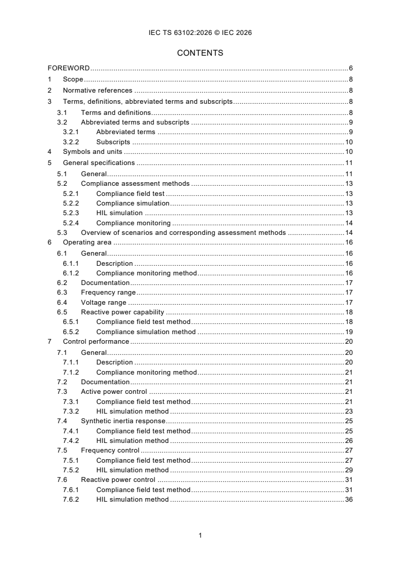
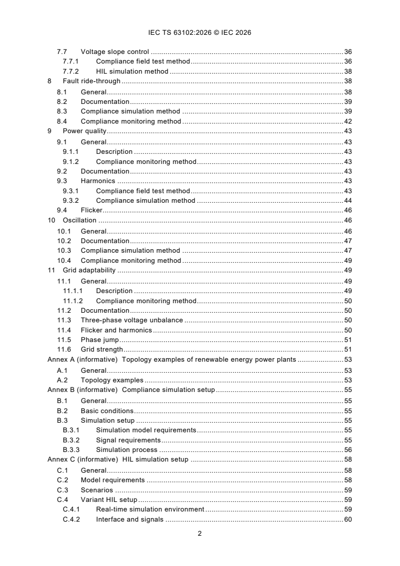
CONTENTS
FOREWORD . 6
1 Scope . 8
2 Normative references . 8
3 Terms, definitions, abbreviated terms and subscripts . 8
3.1 Terms and definitions. 8
3.2 Abbreviated terms and subscripts . 9
3.2.1 Abbreviated terms . 9
3.2.2 Subscripts . 10
4 Symbols and units . 10
5 General specifications . 11
5.1 General . 11
5.2 Compliance assessment methods . 13
5.2.1 Compliance field test . 13
5.2.2 Compliance simulation . 13
5.2.3 HIL simulation . 13
5.2.4 Compliance monitoring . 14
5.3 Overview of scenarios and corresponding assessment methods . 14
6 Operating area . 16
6.1 General . 16
6.1.1 Description . 16
6.1.2 Compliance monitoring method . 16
6.2 Documentation . 17
6.3 Frequency range . 17
6.4 Voltage range . 17
6.5 Reactive power capability . 18
6.5.1 Compliance field test method . 18
6.5.2 Compliance simulation method . 19
7 Control performance . 20
7.1 General . 20
7.1.1 Description . 20
7.1.2 Compliance monitoring method . 21
7.2 Documentation . 21
7.3 Active power control . 21
7.3.1 Compliance field test method . 21
7.3.2 HIL simulation method . 23
7.4 Synthetic inertia response . 25
7.4.1 Compliance field test method . 25
7.4.2 HIL simulation method . 26
7.5 Frequency control . 27
7.5.1 Compliance field test method . 27
7.5.2 HIL simulation method . 29
7.6 Reactive power control . 31
7.6.1 Compliance field test method . 31
7.6.2 HIL simulation method . 36
7.7 Voltage slope control . 36
7.7.1 Compliance field test method . 36
7.7.2 HIL simulation method . 38
8 Fault ride-through . 38
8.1 General . 38
8.2 Documentation . 39
8.3 Compliance simulation method . 39
8.4 Compliance monitoring method . 42
9 Power quality . 43
9.1 General . 43
9.1.1 Description . 43
9.1.2 Compliance monitoring method . 43
9.2 Documentation . 43
9.3 Harmonics . 43
9.3.1 Compliance field test method . 43
9.3.2 Compliance simulation method . 44
9.4 Flicker. 46
10 Oscillation . 46
10.1 General . 46
10.2 Documentation . 47
10.3 Compliance simulation method . 47
10.4 Compliance monitoring method . 49
11 Grid adaptability . 49
11.1 General . 49
11.1.1 Description . 49
11.1.2 Compliance monitoring method . 50
11.2 Documentation . 50
11.3 Three-phase voltage unbalance . 50
11.4 Flicker and harmonics . 50
11.5 Phase jump . 51
11.6 Grid strength . 51
Annex A (informative) Topology examples of renewable energy power plants . 53
A.1 General . 53
A.2 Topology examples . 53
Annex B (informative) Compliance simulation setup . 55
B.1 General . 55
B.2 Basic conditions . 55
B.3 Simulation setup . 55
B.3.1 Simulation model requirements . 55
B.3.2 Signal requirements . 55
B.3.3 Simulation process . 56
Annex C (informative) HIL simulation setup . 58
C.1 General . 58
C.2 Model requirements . 58
C.3 Scenarios . 59
C.4 Variant HIL setup . 59
C.4.1 Real-time simulation environment . 59
C.4.2 Interface and signals . 60
Annex D (informative) Monitoring of electrical performance . 64
D.1 General . 64
D.2 Basic principles . 64
D.3 Hardware and application scenarios . 64
D.3.1 Hardware requirements . 64
D.3.2 Scenarios and application . 65
D.4 Information and data requirements . 67
D.4.1 Information requirements . 67
D.4.2 Data classification . 68
D.4.3 Data acquisition and communication requirements . 69
Annex E (normative) Control performance indexes . 70
Annex F (informative) Harmonics simulation . 71
F.1 Model introduction . 71
F.2 Simulation methods . 71
F.3 Harmonic amplification . 74
F.3.1 Introductory remarks . 74
F.3.2 Harmonic amplification in HVAC offshore wind power systems . 74
Bibliography . 77
Figure 1 – Assessment procedures and methods of RE power plants . 12
Figure 2 – An example of PQ diagram. 20
Figure 3 – Example of figure for set point test of active power . 22
Figure 4 – Example of figure for active power in ramp rate limitation mode . 22
Figure 5 – Example of figure for power plant start up with a required ramp rate . 24
Figure 6 – Example of figure for priority of set-points test . 24
Figure 7 – Example of figure for synthetic inertia response for df/dt . 26
Figure 8 – Example of figure for step frequency injection test . 28
Figure 9 – Example of figure for ramp frequency injection test . 28
Figure 10 – Example of figure for simulated frequency injection test . 28
Figure 11 – Example figure for set point control of reactive power as control reference
(reactive power control mode) . 33
Figure 12 – Example of figure for set point control of voltage as control reference
(voltage control mode) . 34
Figure 13 – Example of figure for reactive power ramp rate limitation . 34
Figure 14 – Example of figure for site test of voltage control Q(U) . 37
Figure 15 – Grid model with symmetrical fault . 39
Figure 16 – Grid model with 2-phase asymmetrical fault . 40
Figure 17 – Example of active power recovery . 42
Figure 18 – Equivalent circuit of the grid and the power plant . 44
Figure 19 – Ideal harmonic current source illustration for harmonic distortion
calculation . 45
Figure 20 – Converter harmonic model as a Norton/Thevenin equivalent circuit . 45
Figure 21 – Impedance bode figure of RE power plants connected to AC grid . 48
Figure 22 – Nyquist figure for stability analysis of RE power plants and VSC-HVDC . 48
Figure 23 – POC current in time-domain and frequency-domain of simulation . 49
Figure 24 – Example figure of phase jump simulation . 51
Figure A.1 – Topology example of hybrid power plants . 53
Figure A.2 – Topology example of control in hybrid power plants . 54
Figure A.3 – Topology example of offshore wind power plants integrated to grid via
VSC-HVDC . 54
Figure B.1 – Diagram of simulation process . 57
Figure C.1 – wind turbine models and interface for HIL . 60
Figure C.2 – PV models and interface for HIL . 60
Figure C.3 – Energy storage models and interface for HIL . 61
Figure C.4 – HIL setup for renewable energy power plants . 61
Figure D.1 – Example of monitoring devices and position . 65
Figure E.1 – Performance indexes of active and reactive power based control . 70
Figure F.1 – Norton equivalent harmonic current source illustration for network
harmonic distortion calculation . 71
Figure F.2 – Power electronics average model Norton equivalent circuit representation . 72
Figure F.3 – Harmonic impedance model of the transmission line . 72
Figure F.4 – Simplified representation for the OWPS used for estimation of harmonic
amplification at POC or any other point of interest . 74
Table 1 – Overview of scenarios and corresponding assessment methods . 15
Table 2 – Example of table for voltage range . 18
Table 3 – Example of table for underexcited reactive power capability . 18
Table 4 – Example of table for overexcited reactive power capability . 19
Table 5 – Example of table for performance indexes of set point test . 23
Table 6 – Example table for active power ramp rate calculation . 23
Table 7 – Example table for priority reference of active power . 25
Table 8 – Example table for performance indexes of synthetic inertia response . 26
Table 9 – Example of table for performance indexes of frequency control response . 29
Table 10 – Example of table for coordination functionality of active power set point and
frequency control . 31
Table 11 – Example of table for reactive power control testing . 35
Table 12 – Example of table for voltage control testing . 35
Table 13 – Example of table for power factor control testing . 35
Table 14 – Example of table for POC-voltage change testing . 36
Table 15 – Example of table for site test of voltage control Q(U) . 37
Table 16 – Example of table for HIL of voltage slope control . 38
Table 17 – Recommended scenario of pre-fault operation modes . 40
Table 18 – Recommended scenario of grid fault types and under/over voltage levels . 41
Table 19 – Example table for fault ride-through simulation results . 42
Table 20 – Example of table for simulation results of unbalanced three-phase voltage . 50
Table 21 – Example of table for SCR range . 52
Table B.1 – Minimum simulation requirements of inputs and outputs . 56
Table C.1 – Minimum requirements of hardware, model and interface in different
scenarios . 59
Table C.2 – Model interface and signals for wind turbine HIL . 62
Table C.3 – Model interface and signals for PV unit HIL. 62
Table C.4 – Model interface and signals for energy storage unit HIL . 63
Table D.1 – Scenarios and application for monitoring . 66
INTERNATIONAL ELECTROTECHNICAL COMMISSION
____________
Grid code compliance assessment methods
for grid connection of renewable energy power plants
FOREWORD
1) The International Electrotechnical Commission (IEC) is a worldwide organization for standardization comprising
all national electrotechnical committees (IEC National Committees). The object of IEC is to promote international
co-operation on all questions concerning standardization in the electrical and electronic fields. To this end and
in addition to other activities, IEC publishes International Standards, Technical Specifications, Technical Reports,
Publicly Available Specifications (PAS) and Guides (hereafter referred to as “IEC Publication(s)”). Their
preparation is entrusted to technical committees; any IEC National Committee interested in the subject dealt with
may participate in this preparatory work. International, governmental and non-governmental organizations liaising
with the IEC also participate in this preparation. IEC collaborates closely with the International Organization for
Standardization (ISO) in accordance with conditions determined by agreement between the two organizations.
2) The formal decisions or agreements of IEC on technical matters express, as nearly as possible, an international
consensus of opinion on the relevant subjects since each technical committee has representation from all
interested IEC National Committees.
3) IEC Publications have the form of recommendations for international use and are accepted by IEC National
Committees in that sense. While all reasonable efforts are made to ensure that the technical content of IEC
Publications is accurate, IEC cannot be held responsible for the way in which they are used or for any
misinterpretation by any end user.
4) In order to promote international uniformity, IEC National Committees undertake to apply IEC Publications
transparently to the maximum extent possible in their national and regional publications. Any divergence between
any IEC Publication and the corresponding national or regional publication shall be clearly indicated in the latter.
5) IEC itself does not provide any attestation of conformity. Independent certification bodies provide conformity
assessment services and, in some areas, access to IEC marks of conformity. IEC is not responsible for any
services carried out by independent certification bodies.
6) All users should ensure that they have the latest edition of this publication.
7) No liability shall attach to IEC or its directors, employees, servants or agents including individual experts and
members of its technical committees and IEC National Committees for any personal injury, property damage or
other damage of any nature whatsoever, whether direct or indirect, or for costs (including legal fees) and
expenses arising out of the publication, use of, or reliance upon, this IEC Publication or any other IEC
Publications.
8) Attention is drawn to the Normative references cited in this publication. Use of the referenced publications is
indispensable for the correct application of this publication.
9) IEC draws attention to the possibility that the implementation of this document may involve the use of (a)
patent(s). IEC takes no position concerning the evidence, validity or applicability of any claimed patent rights in
respect thereof. As of the date of publication of this document, IEC had not received notice of (a) patent(s), which
may be required to implement this document. However, implementers are cautioned that this may not represent
the latest information, which may be obtained from the patent database available at https://patents.iec.ch. IEC
shall not be held responsible for identifying any or all such patent rights.
IEC TS 63102 has been prepared by subcommittee 8A: Grid Integration of Renewable Energy
Generation, of IEC technical committee 8: System Aspects of Electrical Energy Supply. It is a
Technical Specification.
This second edition cancels and replaces the first edition published in 2021. This edition
constitutes a technical revision.
This edition includes the following significant technical changes with respect to the previous
edition:
a) in terms of scope, wind and PV power plants are replaced by the renewable energy power
plants that includes wind power plants, PV power plants and hybrid power plants. Oscillation
and grid adaptability are added in the assessment scope;
b) Clause 5 optimizes the descriptions of compliance field testing, compliance simulation, HIL
simulation and compliance monitoring assessment methods, and recommends
corresponding assessment methods according to different phases of renewable energy
power plants and various assessment items;
c) Clause 6 supplements compliance field test methods for reactive power capability
assessment;
d) Clause 7 adds synthetic inertia response and voltage slope control to control performance
assessment, adjusts recommended contents for field testing and HIL simulation, improves
applicable conditions and reference procedures of assessment methods, and updates
illustrative charts and figures;
e) Clause 8 adds cascaded under and over voltage ride-through assessment cases, and
refines simulation procedures and requirements for simulation results;
f) Clause 9 incorporates compliance simulation and monitoring methods into power quality
assessment;
g) oscillation assessment is newly introduced, adopting combined time-domain and frequency-
domain simulation as well as monitoring methods, with the consideration of renewable
energy power plants connected to grid via HVDC;
h) grid adaptability assessment is newly supplemented, specifically covering the following
withstand capability, such as voltage unbalance factor, flicker and harmonics, phase angle
jump and grid strength;
i) Annex A adds topological structure examples of renewable energy power plants, compliance
simulation setup, and improves contents including HIL simulation setup, monitoring of
electrical performance and harmonics simulation.
The text of this Technical Specification is based on the following documents:
Draft Report on voting
8A/233/DTS 8A/247/RVDTS
Full information on the voting for its approval can be found in the report on voting indicated in
the above table.
The language used for the development of this Technical Specification is English.
This document was drafted in accordance with ISO/IEC Directives, Part 2, and developed in
accordance with ISO/IEC Directives, Part 1 and ISO/IEC Directives, IEC Supplement, available
at www.iec.ch/members_experts/refdocs. The main document types developed by IEC are
described in greater detail at www.iec.ch/publications.
The committee has decided that the contents of this document will remain unchanged until the
stability date indicated on the IEC website under webstore.iec.ch in the data related to the
specific document. At this date, the document will be
– reconfirmed,
– withdrawn, or
– revised.
1 Scope
This document highlights the recommended technical methods of grid code compliance
assessment of renewable energy (RE) power plants connected to the grid, including wind power
plants, photovoltaic (PV) power plants, and hybrid power plants. Hybrid power plants refer to
wind/PV power plants equipped with energy storage systems or combined power plants based
on wind, PV, and energy storage. The electrical behaviour of RE power plants in this document
includes the operating area, control performance, fault ride-through capability, power quality,
oscillation, and grid adaptability.
Compliance assessment is the process of determining whether the electrical behaviour of RE
power plants meets the specific technical requirements in grid codes or technical regulations.
The assessment methods include compliance field test, compliance simulation, hardware-in-
the-loop (HIL) simulation and compliance monitoring. The input for compliance assessment
includes relevant supporting documents, test results, validated simulation models, controller
hardware, and continuous monitoring data. This document focuses exclusively on assessment
methods from a technical perspective. It does not address certification-related procedures.
This document is applicable to RE power plants connected to the electrical power grid.
2 Normative references
The following documents are referred to in the text in such a way that some or all of their content
constitutes requirements of this document. For dated references, only the edition cited applies.
For undated references, the latest edition of the referenced document (including any
amendments) applies.
IEC 60050-415, International Electrotechnical Vocabulary - Part 415: Wind turbine generator
systems
IEC 61400-21-1, Wind energy generation systems - Part 21-1: Measurement and assessment
of electrical characteristics - Wind turbines
IEC 61400-21-2:2023, Wind energy generation systems - Part 21-2: Measurement and
assessment of electrical characteristics - Wind power plants
IEC 62934, Grid integration of renewable energy generation - Terms and definitions
3 Terms, definitions, abbreviated terms and subscripts
3.1 Terms and definitions
For the purposes of this document, the terms and definitions given in the IEC 61400-21-1,
IEC 61400-21-2, IEC 60050-415, IEC 62934 and the following apply.
ISO and IEC also maintain terminological database for use in standardization at the following
addresses:
– IEC Electropedia: available at http://www.electropedia.org/
– ISO Online browsing platform: available at http://www.iso.org/obp
3.1.1
grid code
document that recommends principles and procedures for the activities of connection,
management, planning, development and maintenance of the electrical transmission and
distribution grid, as well as dispatching and metering, etc
3.1.2
grid code compliance
demonstration that the electrical behaviours of power plants satisfy specific technical
requirements in grid codes or technical regulations
3.1.3
hybrid power plant
renewable energy power plants that incorporate multiple types of energy sources, such as wind
power, PV power, and energy storage systems, either in combination or individually
3.1.4
compliance monitoring
monitoring activities with the purpose of demonstrating the ongoing compliance with the
required specifications throughout the operational lifetime of the power plant
3.1.5
compliance simulation
simulation activities conducted in a non-real-time environment, aimed at demonstrating
compliance with the required specifications, particularly in cases where physical testing is
impractical or carries a risk of damaging the facility
3.1.6
compliance field test
procedure conducted on site for power plants to verify if a characteristic or a property complies
with stated requirements in grid codes or technical regulations, using the electrical and control
equipment
3.1.7
hardware-in-the-loop
HIL
simulation method that allows the controller hardware under test to interact in a closed loop
with a real-time simulation model
Note 1 to entry: A simulation model is used to describe the electrical topology of wind/PV power plants, and build
the external real-time testing environment for the hardware. A closed loop test system is composed of the simulation
and embedded physical controller under test.
[SOURCE: IEC 61400-21-2:2023, 3.15]
3.2 Abbreviated terms and subscripts
3.2.1 Abbreviated terms
The following abbreviated terms are used in this document:
CT current transformer
EMT electromagnetic transient
GFM grid forming
HIL hardware-in-the loop
OF over frequency
OLTC on-load tap changer
OVRT over-voltage ride-through
OWPP-HVDC offshore wind power plants integrated into the grid via VSC-HVDC
OWPS offshore wind power systems
PGU power generation unit
POC point of connection
PQ active power and reactive power
PV photovoltaic
RE renewable energy
RMS root mean square
RT real-time
SCR short circuit ratio
SCADA supervisory control and data acquisition
STATCOM static synchronous compensator
TS technical specification
TSO transmission system operator
UF Under Frequency
UVRT under-voltage ride-through
VSC-HVDC voltage source converter based high voltage direct current
VT voltage transformer
3.2.2 Subscripts
F fault
meas measured value
max maximum
min minimum
n nominal
Omax maximum value of over voltage fault
poc-s variable at POC from grid
poc-c variable at POC from power plant
ref reference value
s variable of grid
sa phase A variable of grid
sb phase B variable of grid
sc phase C variable of grid
Umin minimum value of under voltage fault
4 Symbols and units
In this document, the following symbols and units are used.
tested results of the current at POC (A)
I
poc
I harmonic currents produced by the grid (A)
poc-s
I harmonic currents produced by the power plant (A)
poc-c
I equivalent current of the grid (A)
s
I equivalent current of the plant (A)
c
P active power of the power plant (W)
P rated active power (W)
n
P measured active power (p.u.)
meas
active power setpoint value (p.u.)
P
setpoint
P available active power (p.u.)
avail
P maximum long-term flicker
lt
P maximum background long-term flicker
lt0
P maximum long-term flicker caused by power plant
ltRE
Q reactive power reference value (p.u.)
ref
Q measured reactive power (p.u.)
meas
Q maximum reactive power at POC (Var)
max
Q minimum reactive power at POC (Var)
min
short circuit power (VA)
S
k
U rated voltage at POC (V)
n
U voltage of the grid (V)
s
U phase A voltage of the grid (V)
sa
U phase B voltage of the grid (V)
sb
U phase C voltage of the grid (V)
sc
U maximum voltage under normal operation at POC (V)
max
U minimum voltage under normal operation at POC (V)
min
U minimum value of under-voltage according to grid codes (V)
Umin
U maximum value of over-voltage according to grid codes (V)
Omax
U tested results of the voltage at POC (V)
poc
Z equivalent impedance of the power plant (Ω)
c
Z equivalent fault impedance (Ω)
F
Z equivalent impedance of the grid (Ω)
s
phase A equivalent impedance of the grid (Ω)
Z
sa
Z phase B equivalent impedance of the grid (Ω)
sb
Z phase C equivalent impedance of the grid (Ω)
sc
5 General specifications
5.1 General
Technical requirements for RE power plants connecting to the grid are specified in the grid
codes, covering aspects such as operating area, control performance, fault ride-through, power
quality, oscillation, grid adaptability, etc. Some existing IEC standards such as IEC 61400-21
and IEC 61400-27, specify measurement procedures, modelling and validation methods for the
electrical characteristics of wind turbines and wind power plants. This document specifies the
compliance assessment methods for the electrical behaviours specified in grid codes. It applies
to RE power plants, including wind power plants, PV power plants, and hybrid power plants.
Information on topology examples of power plants can be found in Annex A.
Based on the commissioning and operation phases of RE power plants, three phases are
emphasized, and corresponding compliance assessment methods are recommended for each.
The phases are as follows:
– Planning phase
– Commissioning phase
– Commercial operation phase
Methods for compliance assessment can be classified into four general categories:
– Compliance field test
– Compliance simulation
– HIL simulation
– Compliance monitoring
In the planning phase (phase 1), a compliance simulation based on the validated power plant
model is recommended. The models within the power plants should be validated to ensure
higher fidelity with real performance. The models include the validated power generation unit
(PGU) model and the power plant controller model. Type testing is essential for validating the
PGU and other components within the plant model. HIL simulation for validating the control
functionality of the PGU model is optional. Additionally, HIL simulation for the power plant can
be performed if conditions are met, such as the power plant controller hardware, configuration,
and parameters.
In the commissioning phase (phase 2), compliance field test, compliance simulation, and the
HIL method are recommended depending on specific scenarios. Simulations in this phase
should use the validated model based on the test data of power plants. The power plant model
can be partially validated and can also be used in HIL simulations.
In the commercial operation phase (phase 3), compliance monitoring is recommended. Figure 1
shows the assessment procedures and methods of RE power plants.
Figure 1 – Assessment procedures and methods of RE power plants
5.2 Compliance assessment methods
5.2.1 Compliance field test
Field tests are conducted at the point of connection (POC) of the power plant. For offshore wind
power plants integrated into the grid via VSC-HVDC (OWPP-HVDC), field test and other
assessment methods should include the POC, the point of collection, as well as HVDC receiving
and sending terminals.
In this document, compliance field test focuses on steady-state operation, power quality and
control performance. Steady-state operation includes reactive power capability, harmonics and
flicker related to power quality. Control performance encompasses active power control,
synthetic inertia response, frequency control, reactive power control, voltage slope control.
Test equipment requirements vary depending on the parameters being measured. For control
performance, the existing measurement equipment at the power plant substation is generally
sufficient, provided that the required values and precision meet with the relevant standards.
However, specialized equipment is necessary for power quality testing. Relevant requirements
can be found in IEC 61400-21-2.
5.2.2 Compliance simulation
Compliance simulation based on the plant model is a more general method suitable for early
assessment prior to construction and scenarios where testing requirements cannot be fully met.
Simulation models can be categorized into different levels with detail depending on the
assessment scenarios. These models can be used in compliance simulation and HIL simulation.
Generally, the RE power plant model should include the PGU, reactive power compensation
devices, transformer, protection devices, transmission lines, and external power system. The
inclusion of a VSC-HVDC model depends on the plant configuration. The model should
accurately reflect the interaction between the plant and grid regarding voltage and frequency.
Models can be either electromagnetic transient (EMT) models or RMS models.
In general, most electrical performance and compliance assessments should be conducted by
simulation using models, covering steady-state, dynamic performance, and transient
performance. Frequency-domain analysis can be performed using simulation results, which is
helpful for stability and risk assessments. Input requirements for compliance simulation include
disturbances from wind and solar sources, grid voltage and frequency variations, and fault
events caused by grid. Detailed information is provided in Annex B.
5.2.3 HIL simulation
The HIL method focuses on the control performance assessment of power plants and the
functionality test of power plant controllers. It simulates the electrical behavior of power plants
and the grid. The HIL method, which is based on physical controlle
...