

IEC/IEEE 62704-1:2026
(Main)Determining the peak spatial-average specific absorption rate (SAR) in the human body from wireless communications devices, 100 kHz to 10 GHz - Part 1: General requirements for using the finite-difference time-domain (FDTD) method for SAR calculations
- Abstract
IEC/IEEE 62704-1:2026 defines the methodology for the application of the finite-difference time domain (FDTD) technique when used for determining the peak spatial-average specific absorption rate (psSAR) in the human body exposed to wireless communication devices with known uncertainty. It defines methods to validate the computational model of the device under test (DUT) and to assess its uncertainty when used in SAR simulations. Moreover, it defines procedures to determine the psSAR in a cubical volume and to verify the correct implementation of the FDTD simulation software. The applicable frequency range is 100 kHz to 10 GHz.
This document does not recommend specific SAR limits; these are found elsewhere, for example, in the guidelines published by the International Commission on Non-Ionizing Radiation Protection (ICNIRP) or in IEEE Std C95.1.
This second edition cancels and replaces the first edition published in 2017. This edition constitutes a technical revision.
This edition includes the following significant technical changes with respect to the previous edition:
a) specification of a SAR averaging algorithm for the calculation of the psSAR from computational results for arbitrarily shaped homogeneous phantoms, which avoids inconsistencies with respect to the algorithm for SAR averaging algorithm specified in IEC/IEEE 62209-1528 for SAR measurement methods;
b) provision of SHA-256 checksums for all supplemental files;
c) addition of brief informative discussion on developmental stages of IEC and IEEE computational modelling standards for SAR evaluations.
- Status
- Published
- Publication Date
- 11-Oct-2026
- Technical Committee
- TC 106 - Methods for the assessment of electric, magnetic and electromagnetic fields associated with human exposure
- Drafting Committee
- JMT 62704-1 - TC 106/JMT 62704-1
- Current Stage
- PPUB - Publication issued
- Start Date
- 12-Oct-2026
- Completion Date
- 17-Apr-2026
Buy Documents
IEC/IEEE 62704-1:2026 - Determining the peak spatial-average specific absorption rate (SAR) in the human body from wireless communications devices, 100 kHz to 10 GHz - Part 1: General requirements for using the finite-difference time-domain (FDTD) method for SAR calculations
IEC/IEEE 62704-1:2026 is a dual-logo International Standard published by IEC and IEEE. It defines how to apply the finite-difference time-domain (FDTD) method to determine peak spatial-average specific absorption rate (psSAR) in the human body from wireless communications devices over 100 kHz to 10 GHz. It also covers model validation, uncertainty evaluation, whole-body average SAR, and code verification for people who build or review SAR simulation tools.
What does IEC/IEEE 62704-1:2026 specify?
IEC/IEEE 62704-1:2026 specifies the computational method, reporting, uncertainty, and verification framework for SAR simulations based on FDTD. It is aimed at wireless communications devices and human exposure assessment, not at setting SAR limits.
The scope says the document defines methods to:
- validate the computational model of the device under test (DUT)
- assess simulation uncertainty
- determine psSAR in a cubical volume
- verify that FDTD simulation software has been implemented correctly
The document does not set exposure limits. The scope points readers to other sources for limits, such as ICNIRP guidelines and IEEE Std C95.1.
The document is organized into clauses 1 to 8, with supporting annexes and supplemental files.
| Annex | What it covers |
|---|---|
| Annex A | Basic FDTD requirements, update coefficients, stability, and numerical-dispersion background |
| Annex B | SAR Star benchmark, including CAD files, mesh lines, and benchmark output formats |
| Annex C | Practical FDTD considerations, sources and loads, S-parameters, power and efficiency, inhomogeneous meshes, and standards background |
| Annex D | Background on tissue modelling, anatomical models, and recommended phantom models |
| Annex E | Download links and SHA-256 checksums for supplemental files |
What are the key requirements of IEC/IEEE 62704-1:2026?
IEC/IEEE 62704-1:2026 requires a specific three-dimensional FDTD implementation, a defined SAR averaging method, uncertainty evaluation for each test configuration, and code verification against built-in benchmarks. In practice, this means a simulation result only counts if the numerical method, the post-processing, and the software verification all follow the document.
FDTD method and implementation
Clause 5 requires the SAR calculation to use the FDTD method in Cartesian coordinates with a three-dimensional mesh. The electric field and magnetic field are placed on a staggered grid, the field update is explicit and leapfrog-based, and the discretization uses second-order central differences.
That matters because the standard is not accepting any time-domain solver as equivalent. If a tool uses FDTD-like features or an extension such as finite integration technique (FIT) in time domain, the extra features must still be fully verified and at least as accurate as the FDTD method defined here.
SAR calculation and averaging
Clause 6 requires SAR to be calculated from voxel data and then averaged according to the document’s rules. For a single voxel, the standard uses the 12-field-components approach to interpolate the electric field to the voxel centre before calculating SAR with the voxel’s conductivity and mass density.
Clause 6 also defines two psSAR averaging algorithms:
- aligned psSAR for heterogeneous anatomical models, where the averaging cube follows the mesh axes
- homogeneous psSAR for homogeneous phantoms, where the averaging cube is aligned to the phantom surface
This distinction matters in practice because anatomical models and homogeneous phantoms are treated differently. The document says the chosen algorithm and the reference coordinate system must be reported, along with the cube corner coordinates and centre point.
Clause 6 also covers whole-body average SAR. It is calculated from the power dissipated in all body voxels divided by total body mass, so the whole-body result is not a separate measurement but a body-wide sum from the simulation mesh.
Power scaling and reporting
Clause 6 requires SAR results to be scaled to the desired input power or, for plane-wave excitation, to incident power density. The computed input power comes from the complex voltage and current at the feed-point, and the document also allows frequency-domain extraction from DFT or FFT records.
This matters because SAR values must be tied to a stated excitation condition. If device performance changes with temperature, electrical tolerance, or similar effects, the document says that variation has to be handled in the DUT validation or the uncertainty budget.
Clause 6.6 also requires reporting the peak value of the spatial-average SAR distribution and, where applicable, separate values for body and extremity tissues. The psSAR and whole-body average SAR must be reported with their computational uncertainty.
Uncertainty evaluation
Clause 7 requires uncertainty to be evaluated for each exposure configuration. The document separates uncertainty from the test setup, such as positioning, mesh resolution, open boundary conditions, power budget, convergence, and phantom or body dielectric properties, from uncertainty in the developed computational model of the DUT.
That matters because computational SAR is only useful if the reader can judge how much confidence to place in the result. The standard requires the uncertainty budget to combine the identified contributions, and it ties the model validation to representative measurements of the DUT.
Code verification
Clause 8 requires code verification at two levels: code accuracy and canonical benchmarks. The code accuracy tests examine free-space characteristics, planar dielectric boundaries, open boundary conditions, and SAR averaging. The canonical benchmarks include a generic dipole, a microstrip with open boundary conditions, SAR calculation for a SAM phantom and generic phone, and a setup for a system performance check.
In practice, this is the gate that separates a working implementation from an assumed one. Clause 8 says a code that passes the required tests can be labelled as compliant with IEC/IEEE 62704-1 Ed. 2.
What terms does IEC/IEEE 62704-1:2026 define?
IEC/IEEE 62704-1:2026 defines the main terms used in the calculations, averaging, and uncertainty work. These definitions are important because the standard uses them with a precise technical meaning.
- device under test (DUT) - the device or radiating structure being modelled and evaluated in the SAR simulation.
- finite-difference time-domain (FDTD) - a time-domain numerical method for solving Maxwell’s equations on a mesh.
- specific absorption rate (SAR) - the rate at which electromagnetic energy is absorbed per unit mass.
- peak spatial-average specific absorption rate (psSAR) - the maximum average SAR within a local region based on a defined averaging volume or mass.
- spatial-average specific absorption rate (sSAR) - the total power dissipated in the averaging volume divided by the target mass in that volume.
- whole-body average specific absorption rate - the total power dissipated in the whole body divided by body mass.
- voxel - a volume element in the mesh used to discretize the geometry.
- coverage factor (k) - the factor used to convert combined uncertainty into expanded uncertainty with a stated probability.
Who uses IEC/IEEE 62704-1:2026?
IEC/IEEE 62704-1:2026 is used by engineers and organizations that evaluate human exposure from wireless communications devices with computational methods. Typical users are simulation engineers, antenna designers, SAR specialists, compliance laboratories, and manufacturers that need validated SAR results.
It is also relevant to quality managers and technical buyers who need to check whether a SAR tool or study is traceable, repeatable, and backed by the required verification and uncertainty analysis. The standard is especially useful when SAR measurement is difficult or impractical and a computational approach is used instead.
What changed in IEC/IEEE 62704-1:2026 from the previous edition?
IEC/IEEE 62704-1:2026 cancels and replaces the first edition published in 2017. The foreword says this second edition is a technical revision.
The stated technical changes are:
- a SAR averaging algorithm was added for psSAR calculations on arbitrarily shaped homogeneous phantoms
- SHA-256 checksums were added for all supplemental files
- a brief informative discussion was added on the development stages of IEC and IEEE computational modelling standards for SAR evaluations
Which standards are used with IEC/IEEE 62704-1:2026?
IEC/IEEE 62704-1:2026 directly cites one normative reference and also names related documents used alongside it.
| Document | What it contributes |
|---|---|
| IEC/IEEE 62209-1528:2020 | Measurement procedure for SAR assessment, including human models, instrumentation, procedures, and the SAM phantom and testing positions |
| IEC/IEEE 62704-2 | A companion computational SAR standard cited as a way to add device-specific or application-specific definitions |
| IEC/IEEE 62704-3 | A companion computational SAR standard cited as a way to add device-specific or application-specific definitions |
| IEC/IEEE 62704-4 | Identified in the standards history as the FEM part of the IEC/IEEE 62704 series |
| ICNIRP guidelines | Example source for SAR limits outside this document |
| IEEE Std C95.1 | Example source for SAR limits outside this document |
What does the IEC/IEEE 62704-1:2026 document contain?
IEC/IEEE 62704-1:2026 contains the FDTD method definition, the required implementation features, and the SAR post-processing rules used to turn voxel data into psSAR and whole-body average SAR results. It also contains the uncertainty framework needed to support simulations with known uncertainty.
The document includes:
- formulas and procedures for voxel SAR, power scaling, and whole-body averaging
- two psSAR averaging algorithms, one aligned to the mesh and one aligned to a homogeneous phantom surface
- uncertainty tables and budgets for test setup and DUT model contributions
- verification procedures for free-space propagation, dielectric boundaries, open boundaries, and SAR averaging
- benchmark setups such as the generic dipole, microstrip, SAR Star, and SAM phantom/generic phone cases
- practical notes on sources, loads, S-parameters, power, efficiency, and inhomogeneous meshes
- background on tissue properties, anatomical modelling, and recommended phantoms
Annex B supplies benchmark geometry files, mesh lines, and output file formats for verification work. Annex C explains how the FDTD method is used in practice for SAR and related electromagnetic calculations, and Annex D gives the modelling background that supports realistic human-body simulations.
Relations
- Effective Date
- 05-Sep-2023
Buy Documents
IEC/IEEE 62704-1:2026 - Determining the peak spatial-average specific absorption rate (SAR) in the human body from wireless communications devices, 100 kHz to 10 GHz - Part 1: General requirements for using the finite-difference time-domain (FDTD) method for SAR calculations
Get Certified
Connect with accredited certification bodies for this standard

ANCE
Mexican certification and testing association.

BSMI (Bureau of Standards, Metrology and Inspection)
Taiwan's standards and inspection authority.

Intertek Slovenia
Intertek testing, inspection, and certification services in Slovenia.
Sponsored listings
Frequently Asked Questions
IEC/IEEE 62704-1:2026 is a standard published by the International Electrotechnical Commission (IEC). Its full title is "Determining the peak spatial-average specific absorption rate (SAR) in the human body from wireless communications devices, 100 kHz to 10 GHz - Part 1: General requirements for using the finite-difference time-domain (FDTD) method for SAR calculations". This standard covers: IEC/IEEE 62704-1:2026 defines the methodology for the application of the finite-difference time domain (FDTD) technique when used for determining the peak spatial-average specific absorption rate (psSAR) in the human body exposed to wireless communication devices with known uncertainty. It defines methods to validate the computational model of the device under test (DUT) and to assess its uncertainty when used in SAR simulations. Moreover, it defines procedures to determine the psSAR in a cubical volume and to verify the correct implementation of the FDTD simulation software. The applicable frequency range is 100 kHz to 10 GHz. This document does not recommend specific SAR limits; these are found elsewhere, for example, in the guidelines published by the International Commission on Non-Ionizing Radiation Protection (ICNIRP) or in IEEE Std C95.1. This second edition cancels and replaces the first edition published in 2017. This edition constitutes a technical revision. This edition includes the following significant technical changes with respect to the previous edition: a) specification of a SAR averaging algorithm for the calculation of the psSAR from computational results for arbitrarily shaped homogeneous phantoms, which avoids inconsistencies with respect to the algorithm for SAR averaging algorithm specified in IEC/IEEE 62209-1528 for SAR measurement methods; b) provision of SHA-256 checksums for all supplemental files; c) addition of brief informative discussion on developmental stages of IEC and IEEE computational modelling standards for SAR evaluations.
IEC/IEEE 62704-1:2026 defines the methodology for the application of the finite-difference time domain (FDTD) technique when used for determining the peak spatial-average specific absorption rate (psSAR) in the human body exposed to wireless communication devices with known uncertainty. It defines methods to validate the computational model of the device under test (DUT) and to assess its uncertainty when used in SAR simulations. Moreover, it defines procedures to determine the psSAR in a cubical volume and to verify the correct implementation of the FDTD simulation software. The applicable frequency range is 100 kHz to 10 GHz. This document does not recommend specific SAR limits; these are found elsewhere, for example, in the guidelines published by the International Commission on Non-Ionizing Radiation Protection (ICNIRP) or in IEEE Std C95.1. This second edition cancels and replaces the first edition published in 2017. This edition constitutes a technical revision. This edition includes the following significant technical changes with respect to the previous edition: a) specification of a SAR averaging algorithm for the calculation of the psSAR from computational results for arbitrarily shaped homogeneous phantoms, which avoids inconsistencies with respect to the algorithm for SAR averaging algorithm specified in IEC/IEEE 62209-1528 for SAR measurement methods; b) provision of SHA-256 checksums for all supplemental files; c) addition of brief informative discussion on developmental stages of IEC and IEEE computational modelling standards for SAR evaluations.
IEC/IEEE 62704-1:2026 is classified under the following ICS (International Classification for Standards) categories: 17.220.20 - Measurement of electrical and magnetic quantities; 33.060.20 - Receiving and transmitting equipment. The ICS classification helps identify the subject area and facilitates finding related standards.
IEC/IEEE 62704-1:2026 has the following relationships with other standards: It is inter standard links to IEC/IEEE 62704-1:2017. Understanding these relationships helps ensure you are using the most current and applicable version of the standard.
IEC/IEEE 62704-1:2026 is available in PDF format for immediate download after purchase. The document can be added to your cart and obtained through the secure checkout process. Digital delivery ensures instant access to the complete standard document.
Standards Content (Sample)
IEC/IEEE 62704-1 ®
Edition 2.0 2026-10
INTERNATIONAL
STANDARD
Determining the peak spatial-average specific absorption rate (SAR) in the
human body from wireless communications devices, 100 kHz to 10 GHz -
Part 1: General requirements for using the finite-difference time-domain (FDTD)
method for SAR calculations
ICS 17.220.20; 33.060.20 ISBN 978-2-8327-1144-6
All rights reserved. Unless otherwise specified, no part of this publication may be reproduced or utilized in any form or
by any means, electronic or mechanical, including photocopying and microfilm, without permission in writing being
secured. Requests for permission to reproduce should be addressed to either IEC at the address below or IEC’s
member Natio nal Committee in the country of the requester or from IEEE.
IEC Secretariat Institute of Electrical and Electronics Engineers, Inc.
3, rue de Varembé 3 Park Avenue
CH-1211 Geneva 20 New York, NY 10016-5997
Switzerland United States of America
Tel.: +41 22 919 02 11 stds.ipr@ieee.org
info@iec.ch www.ieee.org
www.iec.ch
About the IEC
The International Electrotechnical Commission (IEC) is the leading global organization that prepares and publishes
International Standards for all electrical, electronic and related technologies.
About the IEEE
IEEE is the world’s largest professional association dedicated to advancing technological innovation and excellence for the
benefit of humanity. IEEE and its members inspire a global community through its highly cited publications, conferences,
technology standards, and professional and educational activities.
About IEC/IEEE publications
The technical content of IEC/IEEE publications is kept under constant review by the IEC and IEEE. Please make sure that
you have the latest edition, a corrigendum or an amendment might have been published.
IEC publications search - webstore.iec.ch/advsearchform IEC Products & Services Portal - products.iec.ch
The advanced search enables to find IEC publications by a Discover our powerful search engine and read freely all the
variety of criteria (reference number, text, technical publications previews, graphical symbols and the glossary. With a
committee, …). It also gives information on projects, replaced subscription you will always have access to up to date content
and withdrawn publications. tailored to your needs.
IEC Just Published - webstore.iec.ch/justpublished
Electropedia - www.electropedia.org
Stay up to date on all new IEC publications. Just Published
The world's leading online dictionary on electrotechnology,
details all new publications released. Available online and
containing more than 22 500 terminological entries in English and
once a month by email.
French, with equivalent terms in 25 additional languages. Also
known as the International Electrotechnical Vocabulary (IEV)
IEC Customer Service Centre - webstore.iec.ch/csc
online.
If you wish to give us your feedback on this publication or need
further assistance, please contact the Customer Service
Centre: sales@iec.ch.
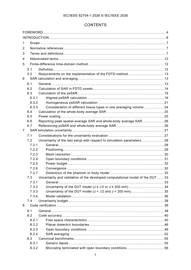
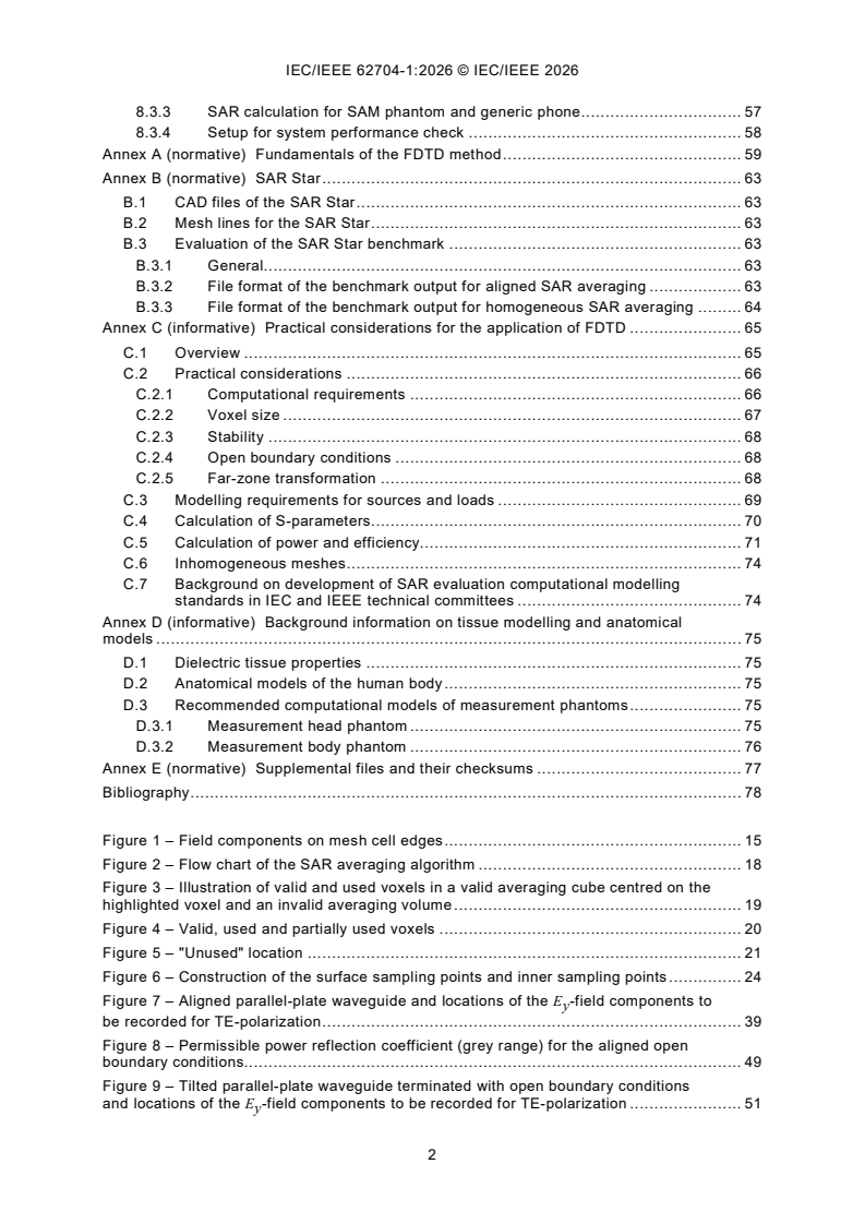
CONTENTS
FOREWORD . 4
INTRODUCTION . 6
1 Scope . 7
2 Normative references . 7
3 Terms and definitions . 7
4 Abbreviated terms. 12
5 Finite-difference time-domain method . 12
5.1 Definition . 12
5.2 Requirements on the implementation of the FDTD method . 13
6 SAR calculation and averaging. 13
6.1 General . 13
6.2 Calculation of SAR in FDTD voxels . 14
6.3 Calculation of the psSAR . 16
6.3.1 Aligned psSAR calculation . 16
6.3.2 Homogeneous psSAR calculation . 21
6.3.3 Consideration of different tissue types in one averaging volume . 24
6.4 Calculation of the whole-body average SAR . 25
6.5 Power scaling . 25
6.6 Reporting peak spatial-average SAR and whole-body average SAR . 26
6.7 Referencing psSAR and whole-body average SAR . 26
7 SAR simulation uncertainty . 27
7.1 Considerations for the uncertainty evaluation . 27
7.2 Uncertainty of the test setup with respect to simulation parameters . 28
7.2.1 General. 28
7.2.2 Positioning . 29
7.2.3 Mesh resolution . 30
7.2.4 Open boundary conditions . 31
7.2.5 Power budget . 32
7.2.6 Convergence . 32
7.2.7 Dielectrics of the phantom or body model . 33
7.3 Uncertainty and validation of the developed computational model of the DUT . 33
7.3.1 General. 33
7.3.2 Uncertainty of the DUT model (d ≥ λ/2 or d ≥ 200 mm) . 34
7.3.3 Uncertainty of the DUT model (d < λ/2 and d < 200 mm) . 35
7.3.4 Model validation. 36
7.4 Uncertainty budget. 38
8 Code verification . 38
8.1 General . 38
8.2 Code accuracy . 40
8.2.1 Free space characteristics . 40
8.2.2 Planar dielectric boundaries . 46
8.2.3 Open boundary conditions . 48
8.2.4 SAR averaging . 52
8.3 Canonical benchmarks . 55
8.3.1 Generic dipole . 55
8.3.2 Microstrip terminated with open boundary conditions . 56
8.3.3 SAR calculation for SAM phantom and generic phone . 57
8.3.4 Setup for system performance check . 58
Annex A (normative) Fundamentals of the FDTD method . 59
Annex B (normative) SAR Star . 63
B.1 CAD files of the SAR Star . 63
B.2 Mesh lines for the SAR Star . 63
B.3 Evaluation of the SAR Star benchmark . 63
B.3.1 General. 63
B.3.2 File format of the benchmark output for aligned SAR averaging . 63
B.3.3 File format of the benchmark output for homogeneous SAR averaging . 64
Annex C (informative) Practical considerations for the application of FDTD . 65
C.1 Overview . 65
C.2 Practical considerations . 66
C.2.1 Computational requirements . 66
C.2.2 Voxel size . 67
C.2.3 Stability . 68
C.2.4 Open boundary conditions . 68
C.2.5 Far-zone transformation . 68
C.3 Modelling requirements for sources and loads . 69
C.4 Calculation of S-parameters . 70
C.5 Calculation of power and efficiency. 71
C.6 Inhomogeneous meshes . 74
C.7 Background on development of SAR evaluation computational modelling
standards in IEC and IEEE technical committees . 74
Annex D (informative) Background information on tissue modelling and anatomical
models . 75
D.1 Dielectric tissue properties . 75
D.2 Anatomical models of the human body . 75
D.3 Recommended computational models of measurement phantoms . 75
D.3.1 Measurement head phantom . 75
D.3.2 Measurement body phantom . 76
Annex E (normative) Supplemental files and their checksums . 77
Bibliography . 78
Figure 1 – Field components on mesh cell edges . 15
Figure 2 – Flow chart of the SAR averaging algorithm . 18
Figure 3 – Illustration of valid and used voxels in a valid averaging cube centred on the
highlighted voxel and an invalid averaging volume . 19
Figure 4 – Valid, used and partially used voxels . 20
Figure 5 – "Unused" location . 21
Figure 6 – Construction of the surface sampling points and inner sampling points . 24
Figure 7 – Aligned parallel-plate waveguide and locations of the E -field components to
y
be recorded for TE-polarization . 39
Figure 8 – Permissible power reflection coefficient (grey range) for the aligned open
boundary conditions. 49
Figure 9 – Tilted parallel-plate waveguide terminated with open boundary conditions
and locations of the E -field components to be recorded for TE-polarization . 51
y
Figure 10 – Permissible power reflection coefficient (grey range) for the tilted open
boundary conditions. 52
Figure 11 – Sketch of the testing geometry of the averaging algorithm . 53
Figure 12 – 3D view of the SAR Star . 53
Figure 13 – Geometry of the microstrip line . 57
Figure 14 – Geometry of the setup for the system performance check . 57
Figure A.1 – Voxel showing the arrangement of the electric-field and magnetic-field
vector components on a staggered mesh . 61
Figure A.2 – Voxels with different dielectric properties surrounding a mesh edge with
an E -component . 62
y
Figure C.1 – FDTD voltage source with source resistance . 70
Figure C.2 – Four magnetic field components surrounding the electric field component
where the source is located . 70
Figure C.3 – Power reference planes . 73
Table 1 – Voxel states during SAR averaging . 17
Table 2 – Factors contributing to the uncertainty of measurement and computational
SAR evaluations . 28
Table 3 – Budget of the uncertainty contributions of the computational algorithm and of
the rendering of the test- or simulation-setup . 29
Table 4 – Budget of the uncertainty of the developed model of the DUT . 37
Table 5 – Computational uncertainty budget . 38
Table 6 – Results of the evaluation of the numerical dispersion characteristics . 45
Table 7 – Results of the evaluation of the numerical reflection coefficient . 48
Table 8 – Parameters for the incident electric field of Formula (30) . 55
Table 9 – Results of the dipole evaluation . 56
Table 10 – Results of the microstrip evaluation . 56
Table 11 – 1 g and 10 g psSAR for the SAM phantom exposed to the generic phone for
1 W accepted antenna power as specified in [8] . 57
Table 12 – Dielectric properties of the tissue simulant and of the phantom shell
specified in IEC/IEEE 62209-1528:2020 and [31] . 58
Table 13 – Mechanical parameters of the setup [31]. 58
Table 14 – psSAR normalized to 1 W forward power and feedpoint impedance [31] . 58
Determining the peak spatial-average specific absorption rate (SAR)
in the human body from wireless communications devices,
100 kHz to 10 GHz -
Part 1: General requirements for using the finite-difference
time-domain (FDTD) method for SAR calculations
FOREWORD
1) The International Electrotechnical Commission (IEC) is a worldwide organization for standardization comprising
all national electrotechnical committees (IEC National Committees). The object of IEC is to promote international
co-operation on all questions concerning standardization in the electrical and electronic fields. To this end and
in addition to other activities, IEC publishes International Standards, Technical Specifications, Technical Reports,
Publicly Available Specifications (PAS) and Guides (hereafter referred to as "IEC document(s)"). Their
preparation is entrusted to technical committees; any IEC National Committee interested in the subject dealt with
may participate in this preparatory work. International, governmental and non-governmental organizations liaising
with the IEC also participate in this preparation.
IEEE Standards documents are developed within IEEE Societies and subcommittees of IEEE Standards
Association (IEEE SA) Board of Governors. IEEE develops its standards through an accredited consensus
development process, which brings together volunteers representing varied viewpoints and interests to achieve
the final product. IEEE standards are documents developed by volunteers with scientific, academic, and industry-
based expertise in technical working groups. Volunteers involved in technical working groups are not necessarily
members of IEEE or IEEE SA and participate without compensation from IEEE. While IEEE administers the
process and establishes rules to promote fairness in the consensus development process, IEEE does not
independently evaluate, test, or verify the accuracy of any of the information or the soundness of any judgments
contained in its standards.
IEC collaborates closely with IEEE in accordance with conditions determined by agreement between the two
organizations. This Dual Logo International Standard was jointly developed by the IEC and IEEE under the terms
of that agreement.
2) The formal decisions of IEC on technical matters express, as nearly as possible, an international consensus of
opinion on the relevant subjects since each technical committee has representation from all interested IEC
National Committees. The formal decisions of IEEE on technical matters, once consensus within IEEE Societies
and Standards Coordinating Committees has been reached, is determined by a balanced ballot of materially
interested parties who indicate interest in reviewing the proposed standard. Final approval of the IEEE standards
document is given by the IEEE Standards Association (IEEE SA) Standards Board.
3) IEC/IEEE Publications have the form of recommendations for international use and are accepted by IEC National
Committees/IEEE Societies in that sense. While all reasonable efforts are made to ensure that the technical
content of IEC/IEEE Publications is accurate, IEC or IEEE cannot be held responsible for the way in which they
are used or for any misinterpretation by any end user.
4) In order to promote international uniformity, IEC National Committees undertake to apply IEC Publications
(including IEC/IEEE Publications) transparently to the maximum extent possible in their national and regional
publications. Any divergence between any IEC/IEEE Publication and the corresponding national or regional
publication shall be clearly indicated in the latter.
5) IEC and IEEE do not provide any attestation of conformity. Independent certification bodies provide conformity
assessment services and, in some areas, access to IEC marks of conformity. IEC and IEEE are not responsible
for any services carried out by independent certification bodies.
6) All users should ensure that they have the latest edition of this publication.
7) No liability shall attach to IEC or IEEE or their directors, employees, servants or agents including individual
experts and members of technical committees and IEC National Committees, or volunteers of IEEE Societies and
the Standards Coordinating Committees of the IEEE Standards Association (IEEE SA) Standards Board, for any
personal injury, property damage or other damage of any nature whatsoever, whether direct or indirect, or for
costs (including legal fees) and expenses arising out of the publication, use of, or reliance upon, this IEC/IEEE
Publication or any other IEC or IEEE Publications.
8) Attention is drawn to the normative references cited in this publication. Use of the referenced publications is
indispensable for the correct application of this publication.
9) Attention is drawn to the possibility that implementation of this IEC/IEEE Publication may require use of material
covered by patent rights. By publication of this standard, no position is taken with respect to the existence or
validity of any patent rights in connection therewith. IEC or IEEE shall not be held responsible for identifying
Essential Patent Claims for which a license may be required, for conducting inquiries into the legal validity or
scope of Patent Claims or determining whether any licensing terms or conditions provided in connection with
submission of a Letter of Assurance, if any, or in any licensing agreements are reasonable or non-discriminatory.
Users of this standard are expressly advised that determination of the validity of any patent rights, and the risk
of infringement of such rights, is entirely their own responsibility.
IEC/IEEE 62704-1 was prepared by IEC technical committee 106: Methods for the assessment
of electric, magnetic and electromagnetic fields associated with human exposure, in
cooperation with the International Committee on Electromagnetic Safety of the IEEE Standards
Association, under the IEC/IEEE Dual Logo Agreement between IEC and IEEE. It is an
International Standard.
This document is published as an IEC/IEEE Dual Logo standard.
This second edition cancels and replaces the first edition published in 2017. This edition
constitutes a technical revision.
This edition includes the following significant technical changes with respect to the previous
edition:
a) specification of a SAR averaging algorithm for the calculation of the psSAR from
computational results for arbitrarily shaped homogeneous phantoms, which avoids
inconsistencies with respect to the algorithm for SAR averaging algorithm specified in
IEC/IEEE 62209-1528 for SAR measurement methods;
b) provision of SHA-256 checksums for all supplemental files;
c) addition of brief informative discussion on developmental stages of IEC and IEEE
computational modelling standards for SAR evaluations.
This standard contains attached files in the form of CAD models and reference results described
in Annex B and Annex D. Download links and checksums for these files can be found in
Annex E.
The text of this International Standard is based on the following IEC documents:
Draft Report on voting
106/722/FDIS 106/733/RVD
Full information on the voting for its approval can be found in the report on voting indicated in
the above table.
The language used for the development of this International Standard is English.
This document was drafted in accordance with the rules given in the ISO/IEC Directives, Part 2,
available at www.iec.ch/members_experts/refdocs. The main document types developed by IEC
are described in greater detail at www.iec.ch/publications/.
A list of all parts in the IEC/IEEE 62704 series, published under the general title Determining
the peak spatial-average specific absorption rate (SAR) in the human body from wireless
communications devices, 100 kHz to 10 GHz, can be found on the IEC website.
Future documents in this series will carry the new general title as cited above. Titles of existing
documents in this series will be updated at the time of the next edition.
The IEC Technical Committee and IEEE Technical Committee have decided that the contents
of this document will remain unchanged until the stability date indicated on the IEC website
under webstore.iec.ch in the data related to the specific document. At this date, the document
will be
– reconfirmed,
– withdrawn, or
– revised.
INTRODUCTION
Computational techniques have reached a level of maturity which allows their use in specific
absorption rate (SAR) assessment of wireless communication devices. Some wireless
communication devices are used in situations where SAR measurement is extremely complex
or not possible at all. The benefits of consensus standards to users and regulators include
standardized and accepted protocols, anatomically correct body models, verification and
validation techniques, benchmark data, reporting format and means for estimating the
computational uncertainty in order to produce valid, accurate, repeatable, and reproducible
data.
1 Scope
This part of IEC/IEEE 62704 defines the methodology for the application of the finite-difference
time domain (FDTD) technique when used for determining the peak spatial-average specific
absorption rate (psSAR) in the human body exposed to wireless communication devices with
known uncertainty. It defines methods to validate the computational model of the device under
test (DUT) and to assess its uncertainty when used in SAR simulations. Moreover, it defines
procedures to determine the psSAR in a cubical volume and to verify the correct implementation
of the FDTD simulation software. The applicable frequency range is 100 kHz to 10 GHz.
This document does not recommend specific SAR limits; these are found elsewhere, for
example, in the guidelines published by the International Commission on Non-Ionizing
Radiation Protection (ICNIRP) [1] or in IEEE Std C95.1 [2].
2 Normative references
The following documents are referred to in the text in such a way that some or all of their content
constitutes requirements of this document. For dated references, only the edition cited applies.
For undated references, the latest edition of the referenced document (including any
amendments) applies.
IEC/IEEE 62209-1528:2020, Measurement procedure for the assessment of specific absorption
rate of human exposure to radio frequency fields from hand-held and body-mounted wireless
communication devices - Human models, instrumentation, and procedures (Frequency range of
4 MHz to 10 GHz)
3 Terms and definitions
For the purposes of this document, the following terms and definitions apply.
IEC, ISO and IEEE maintain terminological databases for use in standardization at the following
addresses:
– IEC Electropedia: available at https://www.electropedia.org/
– ISO Online browsing platform: available at https://www.iso.org/obp
– IEEE Dictionary Online: available at https://dictionary.ieee.org
3.1
source
one or more edges of the mesh to which an associated signal feeds electric or magnetic energy
Note 1 to entry: The amplitude of the signal is proportional to an arbitrary function of time.
3.2
feed-point
part of the radiating structure where the radio-frequency currents start to support
the electromagnetic fields that carry energy away from the antenna
Note 1 to entry: Often the feed-point of the antenna is not accessible because of mechanical support requirements;
in this case a connection point is available to inject radio-frequency energy into the antenna. Normally, the connection
point is a simple connector or a waveguide flange. If not collocated, the connection and the feed-point of an antenna
are interconnected by one or more sections of transmission line. By measuring the antenna impedance at the
connection point, if the electrical characteristics of the transmission lines between the connection and the feed-point
are known, it is possible to calculate the antenna feed-point impedance.
___________
Numbers in square brackets refer to the bibliography.
3.3
antenna feed-point impedance
terminal or driving-point impedance
ratio of complex voltage to complex current at the terminals of a transmitting antenna, or the
ratio of the open-circuit voltage to the short-circuit current at the terminals of a receiving
antenna
3.4
background material
material or tissue which is not considered for the averaging volume
Note 1 to entry: Most typically, a background material will be any lossless material, such as the free-space or air
surrounding the anatomical model. It also includes air enclosures or other lumina inside the body and tissues that
have been excluded from averaging, for example, by user selection.
3.5
benchmark
simulation test specifically defined to verify simulation results based on comparison with a
reference
3.6
body
geometrical distribution of the dielectric properties and the mass densities of all live body
tissues including body fluids
Note 1 to entry: The contents of body lumina or foreign matter, such as medical implants or jewellery, are not
considered as part of the body.
3.7
conductivity
σ
ratio of the magnitude of the conduction-current density in a medium to the electric field strength
Note 1 to entry: Conductivity is expressed in units of siemens per metre (S/m).
3.8
conservative exposure
estimate of the peak spatial-average SAR and whole-body average SAR as defined in this
document that is representative of what is expected to occur in the body of a significant majority
of the population during normal operating conditions of wireless communication devices
[SOURCE: IEC/IEEE 62209-1528:2020, modified – In the definition, whole-body average SAR
has been added and explicit mention of uncertainties has been deleted.]
3.9
coverage factor
k
factor that is used to obtain the expanded uncertainty from the combined uncertainty with a
known probability of containing the true value of the measurand
3.10
far-field
region of the field of an antenna where the angular field distribution is essentially independent
of the distance from the antenna
Note 1 to entry: In this region, the field has predominantly plane wave characteristics, i.e. the electric field strength
and magnetic field strength distributions are locally uniform in planes transverse to the direction of propagation.
Note 2 to entry: For larger antennas especially, the far-field is also referred to as the Fraunhofer region.
3.11
mesh
discrete representation of the simulation model as a set of voxels in a regular three-dimensional
Cartesian arrangement
Note 1 to entry: In the scientific literature, the mesh is often referred to as "grid".
3.12
near-field
region in the field of an antenna, located near the antenna, in which the electric and magnetic
fields do not have substantial plane-wave characteristics, but vary considerably from point to
point
Note 1 to entry: The term near-field is often vaguely defined and has different meanings for large and small
antennas. The near-field is further subdivided into the reactive near-field, which is closest to the antenna and contains
most or nearly all of the stored energy associated with the field of the antenna, and the radiating near-field. If the
antenna has a maximum overall dimension that is not large compared to the wavelength, the radiating near-field
possibly does not exist. For antennas large in terms of wavelength, the radiating near-field is sometimes referred to
as the Fresnel region.
Note 2 to entry: For most antennas, the outer boundary of the reactive near-field is commonly taken to exist at a
distance of λ/2π from the antenna surface.
3.13
perfect electric conductor
PEC
material with infinite electrical conductivity which does not dissipate any energy
3.14
relative permittivity
ε
r
ratio of the complex permittivity to the permittivity of free space
Note 1 to entry: The complex relative permittivity, ε = ε /ε , of an isotropic, linear, lossy dielectric medium is from
r 0
Formula (1)
ε ′′
σ
r
′ ′′ ′ ′ ′
ε = ε − jε = ε − j = ε 1− j = ε (1− j tanδ ) (1)
r r r r r r
ωε ε ′
0 r
where
−12
ε is the free space permittivity (8,854 × 10 F/m);
′
ε is the relative permittivity or dielectric constant;
r
σ is the conductivity in siemens per metre (S/m);
tanδ is the loss tangent.
jωt
Note 2 to entry: For the purposes of this document, the convention e is used to describe time-varying electric
fields.
3.15
permeability
µ
ratio of the magnetic flux density to the magnetic field strength at a point
Note 1 to entry: The permeability is expressed in units of henry per metre (H/m).
3.16
reactive field
electric and magnetic fields surrounding an antenna or other electromagnetic devices that result
in storage rather than propagation of electromagnetic energy
3.17
root-mean-square
RMS
positive square root of the mean value of the square of the function
taken over a given period
Note 1 to entry: For a periodic function y of t, the positive square root of y is from Formula (2):
(2)
Y = y (t) dt
RMS ∫
T
where
Y is the RMS value of y;
RMS
t is any value of time;
T is the period.
3.18
root-sum-square
RSS
positive square root of the sum of the squares of the elements of a set of numbers
3.19
scattering
process that causes waves incident on discontinuities or boundaries of media to be changed in
direction, phase, or polarization
3.20
specific absorption rate
SAR
time derivative (rate) of the incremental energy (dW) absorbed by (dissipated in) an incremental
mass (dm) contained in a volume element (dV) of a given density (ρ)
d dW d dW
SAR =
=
dt dm dt ρ dV
Note 1 to entry: SAR is expressed in units of watts per kilogram (W/kg) or equivalently milliwatts per gram (mW/g).
Note 2 to entry: SAR can be related to the electric field at a point by
σ | E |
SAR =
2ρ
where
σ is the conductivity of the tissue in siemens per metre (S/m);
ρ is the mass density of the tissue in kilograms per cubic metre (kg/m );
E is the peak electric field vector in volts per metre (V/m).
Note 3 to entry: SAR can be related to the increase in temperature at a point by
c∆T
SAR ≈
∆t
t=0
where
∆T is the change in temperature in degree Celsius (°C);
∆t is the duration of exposure in seconds (s);
c is the specific heat capacity in joules per kilogram and degree Celsius (J/kg °C).
This assumes that measurements are made under "ideal" circumstances, i.e. no heat loss by thermal diffusion, heat
radiation, or thermoregulation (blood flow, sweating, etc.). Moreover, this expression is valid only in the initial, linear
regime of the temperature-time curve. If this linear regime does not exist, the provided expression is not used.
3.20.1
peak spatial-average specific absorption rate
psSAR
maximum average SAR within a local region based on a specific averaging volume or mass
Note 1 to entry: SAR is expressed in watts per kilogram (W/kg) or equivalently milliwatts per gram (mW/g).
Note 2 to entry: The specific averaging volume or mass can be, for example, any 1 g or 10 g of tissue in the shape
of a cube.
Note 3 to entry: For the purpose of this document, when the averaging mass is not specified the peak spatial-
average SAR refers to both 1 g and 10 g quantities. In several tables in this document, the peak spatial-average SAR
for 1 g and 10 g is simply denoted as 1 g and 10 g SAR.
3.20.2
spatial-average specific absorption rate
sSAR
ratio of the total power dissipated in the averaging volume to the target mass of tissue within
that volume
Note 1 to entry: SAR is expressed in watts per kilogram (W/kg) or equivalently milliwatts per gram (mW/g).
Note 2 to entry: The specific averaging volume or mass can be, for example, any 1 g or 10 g of tissue in the shape
of a cube.
3.20.3
whole-body average specific absorption rate
quantity calculated as the power dissipated in the entire body divided by its mass
Note 1 to entry: SAR is expressed in watts per kilogram (W/kg) or equivalently milliwatts per gram (mW/g).
3.21
update coefficient
numerical value assigned to the voxel edges and faces calculated from the dielectric and
magnetic properties of the voxels that surround it
Note 1 to entry: The update coefficient is used to advance the numerical values of the electric and magnetic fields
in the mesh in time based on their present and past values.
3.22
voxel
volume element of the geometry to be discretized in the mesh
Note 1 to entry: In FDTD simulations for SAR calculation, the voxel is assigned the permittivity, permeability, the
electric and magnetic conductivities and the mass density of the geometry. The electric-field components of the mesh
are located in a tangential direction on the centres of the voxel edges, and the magnetic-field components of the
mesh are located in a normal direction on the centres of the voxel faces. Each edge and face is assigned an update
coefficient.
4 Abbreviated terms
ASCII American Standard Code for Information Interchange
CFL Courant–Friedrichs–Lewy
CT computed tomography
DFT discrete Fourier transformation
DUT device under test
FDTD finite-difference time-domain
FFT fast Fourier transformation
FIT finite integration technique
MIMO multiple input multiple output
MRI magnetic resonance imaging
PEC perfect electric conductor
PMC perfect magnetic conductor
PML perfectly matched layers
psSAR peak spatial-average specific absorption rate
RMS root mean square
RSS root sum square
SAM specific anthropomorphic mannequin
SAR specific absorption rate
sSAR spatial-average specific absorption rate
5 Finite-difference time-domain method
5.1 Definition
This document applies the finite-difference time-domain (FDTD) method to calculate SAR.
FDTD is extensively used for bio-electromagnetic calculations, dating back to 1975 for the
analysis of microwave heating of a human eye (Taflove and Brodwin [3]). Initially, the user shall
determine the applicability of this document by determining whether the specific computational
solution of Maxwell’s equations under consideration qualifies as an implementation of FDTD.
This is not entirely straightforward since there have been many variations of the FDTD method
developed over the time since Kane Yee’s original paper in 1966 [4], which may be taken as
defining the fundamental FDTD method. Since then, the method has received significant
attention in the scientific community. Numerous articles on the method and its extensions and
applications have been published. Several textbooks on the FDTD method recapitulate its
fundamentals, its further developments and its use ([5], [6]). Details on the application of the
FDTD method are given in Annex C.
For the application of this document, the implementation of FDTD in the region where SAR is
being calculated shall include the following characteristics.
– The electric field components are located on the edges of a Cartesian mesh composed of
rectangular parallelepipeds.
– The magnetic field components are located on the edges of a Cartesian mesh composed of
rectangular parallelepipeds which is offset from the electric field mesh by a half-voxel in
each direction.
– The computational method is a finite-difference approximation of the Maxwell curl equations
using central differences which are (at least globally) second-order accurate and may
therefore include non-uniform meshes, which are also second-order accurate (Monk and
Süli [7]).
– The computational method solves for both electric and magnetic fields by a fully explicit
leapfrog time-stepping process.
– Gauss’s laws are implicitly enforced, the fields are divergence-free, and charge is
conserved.
– The time-stepping algorithm is non-dissipative. Thus, there is no spurious decay of energy
due to non-physical artefacts of the algorithm, and artificial dissipation is not required for
stability.
NOTE Complex numerical dispersion in non-uniform meshes leads to spurious rise or decay of field amplitudes [7].
For the applications of the scope of this document, these effects are generally negligible. The impact of the numerical
dispersion is assessed within the uncertainty evaluation (Clause 7).
5.2 Requirements on the implementation of the FDTD method
The basic requirements on the FDTD method are given in Annex A. For compliance with this
document, the FDTD method shall be implemented according to these requirements. The
method shall be implemented in Cartesian coordinates in three spatial dimensions. Moreover,
SAR calculation and averaging shall be implemented according to Clause 6. The
implementation of the FDTD method shall be verified according to Clause 8.
Other methods or extensions, or both, of FDTD that satisfy the above definitions but provide
additional features may be applied provided that these features have been fully verified
according to the procedures in this document; code verification and benchmarks, etc. These
alternative methods shall provide at least the same accuracy as the FDTD method defined
above. The finite integration technique (FIT) in time domain can be regarded as an extension
of FDTD in this context.
6 SAR calculation and averaging
6.1 General
Present RF exposure standards and guidelines specify time averaged whole-body average SAR
limits and psSAR limits, neither of which shall be exceeded. The psSAR is usually averaged
over a specified mass of tissue in a cubical volume, such as the trunk, the head, an extremity
(e.g. limbs) or the pinnae. Averaging masses are specified in [1], [2] or other applicable
guidelines.
The measurement standard that defines the SAM phantom and the testing positions is
IEC/IEEE 62209-1528. The frequency range of IEC/IEEE 62209-1528 is from 4 MHz to 10 GHz,
whereas the lower end of the frequency range of this document is 100 kHz. The assumptions
on which the SAM phantom and the testing positions are based and which are outlined in
IEC/IEEE 62209-1528 apply for SAR assessment regardless of the frequency limit. As the
FDTD method does not have any intrinsic frequency limitations, the SAM phantom and the
testing positions of IEC/IEEE 62209-1528 can be applied over the entire frequency range of
this document.
Most computational studies involving the calculation of the psSAR in anatomical models of the
human body with complex tissue distribution apply Cartesian meshes and align the cubical
averaging volume with the mesh axes [8]. SAR measurement methods using homogeneous
body phant
...