

FprEN 14420-7
(Main)Hose fittings with clamp units - Part 7: Cam locking couplings
- Abstract
This document specifies the design, materials, dimensions and marking requirements for cam locking couplings that serve as the link between hoses and connections to transport liquids, solids and gases, except liquid gas and steam.
For all sizes of aluminium cast material couplings and for all couplings of size DN 100, the pressure range is from −0,8 bar to 10 bar in the working temperature range from −20 °C to +65 °C. All other couplings according to this document are capable of operating within the pressure range from 0,8 bar to 16 bar in the working temperature range from −20 °C to +65 °C.
- Status
- Not Published
- Publication Date
- 20-Jan-2027
- Technical Committee
- CEN/TC 218 - Rubber and plastics hoses and hose assemblies
- Current Stage
- 5020 - Submission to Vote - Formal Approval
- Start Date
- 01-Oct-2026
- Due Date
- 26-Feb-2027
- Completion Date
- 01-Oct-2026


FprEN 14420-7 is a draft European Standard from CEN for hose fittings with clamp units, Part 7, covering cam locking couplings. It specifies the design, materials, dimensions and marking for couplings that link hoses to connections for transporting liquids, solids and gases, except liquid gas and steam. The standard also sets the pressure and working-temperature ranges that these couplings are intended to meet.
What does FprEN 14420-7 specify?
FprEN 14420-7 specifies cam locking couplings used as the connection between hoses and fixed or mating connections. It covers the coupling body, the adapter side, gaskets, cam arms, pins, rings, dust cap and dust plug variants.
The document is organized into clauses on scope, normative references, terms and definitions, requirements, survey, types of connection, designation, dimensions, materials, marking, and type testing and quality control. Annex A gives gauges for cam-locking couplings.
| Annex | What it covers |
|---|---|
| Annex A | Gauges for cam-locking couplings |
The scope limits the service medium to liquids, solids and gases, and excludes liquid gas and steam. It also gives operating envelopes for pressure and temperature, which matters when selecting a coupling for a hose system or checking whether a design is suitable for a specific duty.
What are the key requirements of FprEN 14420-7?
Construction and function
Clause 4.1 requires the lever shape, adapter shape and main gasket dimensions to work together so that hose twisting and vibration do not cause leakage. In practice, this means the coupling is designed to stay sealed in service, not only when newly assembled.
Clause 4.1 also requires cam arms to be manually operable and usable without tools. That matters for fast connection and disconnection in the field, where operators need to close or open the coupling directly.
The same clause notes that conformity supports compatibility between couplers and adapters from different manufacturers. It also warns that spare-part interchangeability is only assured for gaskets, not for all other parts.
Temperature and pressure limits
Clause 4.2 sets the working temperature range for couplings fitted with nitrile butadiene rubber (NBR) gaskets at −20 °C to +65 °C. The scope adds that aluminium cast material couplings and all couplings of size DN 100 are in the pressure range from −0.8 bar to 10 bar, while all other couplings covered by the document are in the range from 0.8 bar to 16 bar, both over the same temperature range.
For a buyer or engineer, this is the first selection filter. It tells you whether the coupling family fits the pressure, vacuum and temperature conditions of the hose line before you look at exact dimensions.
Connection types and sizes
Clause 6 defines the connection combinations: DF with AF, BF with FF, DW with AW, CC with EC, and DC with DP. It also ties the threaded versions to the relevant thread standards and distinguishes internal thread, external thread, welding connection, hose tail, dust cap and dust plug arrangements.
Clause 8 then gives figures and tables for the dimensions of each type. This is the practical part used for design, procurement and inspection, because the nominal size alone is not enough to ensure that the hose end, mating part and retaining elements will fit.
Tolerances, parts and gauges
Clause 8.1 states that dimensions are in millimetres and that general tolerances follow EN 22768-1 and EN 22768-2. Annex A adds a gauge A1 for cam-locking couplings, with its own dimensions and designation.
That matters in manufacture and quality control because it gives a common inspection basis. If a producer or tester uses the prescribed tolerances and gauge dimensions, parts can be checked against the same acceptance geometry.
Materials
Clause 9 limits the permitted materials for the coupler and adapter bodies, cam arms, pins and rings to specified copper-zinc alloys, copper-tin alloys, aluminium alloys and stainless steels. Main gaskets and thread gaskets must be resistant to the conveyed fluid and must be non-asbestos materials.
For gasket selection, the document names preferred materials such as NBR, FPM, CSM and PTFE encapsulated for main gaskets, and PUR, PTFE, NBR, FPM and EPDM for thread gaskets. In practice, that means the gasket choice must be matched to the media and the service environment, not chosen only by size.
Marking and conformity
Clause 10 requires durable outside marking, where surface area allows, on bodies and male parts. The marking includes EN 14420-7, the manufacturer’s identification, type and nominal size, PN for at least aluminium cast material, and material number for at least stainless steels.
Clause 11 sends type testing and quality control to EN 14420-1:2013, Clause 7. That links this part to the series-wide test and control approach used to confirm product conformity.
What terms does FprEN 14420-7 define?
- Nominal size (DN) - A reference size designation for pipework components that uses the letters DN followed by a whole number; it is for identification, not for direct calculation.
- PN - A reference designation for a hose fitting that combines mechanical and dimensional characteristics; it identifies a class or family rather than a measured value.
- Main gasket - The gasket between the male and female parts of the coupling; it is the primary sealing interface.
- Thread gasket - A flat-faced gasket for threads according to EN ISO 228-1; it supports the threaded connection seal.
- Cam locking couplings - Couplings that use cam arms to lock the mating parts together quickly by hand.
- Hose fittings with clamp units - The series family name for these fittings, showing that the coupling is part of a larger hose connection system.
Who uses FprEN 14420-7?
FprEN 14420-7 is used by manufacturers of hose fittings and hose assemblies, especially where cam locking couplings are made as standardized components. It is also relevant to quality managers, test laboratories and buyers who need to specify the coupling type, material and nominal size with confidence.
In practice, it supports work in hose systems for liquids, solids and gases. That includes design, sourcing, incoming inspection, type testing, and checking whether a coupling can be assembled, sealed and marked in the required way.
What changed in FprEN 14420-7 from the previous edition?
FprEN 14420-7 will supersede EN 14420-7:2022/AC:2023. The foreword lists two technical changes:
- In Figure 3, the symbol d6 was deleted because it does not appear in the document.
- In Figure 6, the missing explanation for entry 1 was added.
Which standards are used with FprEN 14420-7?
| Referenced standard | What it contributes |
|---|---|
| EN 755-2 | Mechanical properties for extruded aluminium rod, bar, tube and profiles |
| EN 1706 | Chemical composition and mechanical properties for aluminium castings |
| EN 1982 | Copper and copper alloy ingots and castings |
| EN 10088-1 | Stainless steel listing for selected materials |
| EN 10213 | Steel castings for pressure purposes |
| EN 12420 | Copper and copper alloy forgings |
| EN 14420-1:2013 | Requirements, fixing and connection types, designation, testing, and the type testing and quality control method used here |
| EN 14420-2 | Hose side parts of hose tail |
| EN 14420-5 | Threaded connections and the thread gasket reference |
| EN 22768-1 | General linear and angular tolerances |
| EN 22768-2 | General geometrical tolerances, cited here for dimensions and tolerances |
| EN ISO 8330 | Hose and hose assembly vocabulary used for terms and definitions |
| ISO 272 | Width across flats for hexagon products |
What does the FprEN 14420-7 document contain?
The document contains a survey of coupling parts, connection types and designation examples, followed by detailed dimensional figures and tables for each coupler and adapter type. It gives the dimensional basis for DF, BF, DW, CC and DC couplers, and AF, FF, AW, EC and DP adapters, which is the material a designer or inspector uses to match parts correctly.
It also contains the material lists for bodies and smaller components, the marking rules, and the quality-control link to EN 14420-1. Annex A adds a gauge definition for checking cam-locking couplings, which is useful for inspection and conformity assessment.
Relations
- Effective Date
- 12-Mar-2025
Get Certified
Connect with accredited certification bodies for this standard

Institut za varilstvo d.o.o. (Welding Institute)
Slovenia's leading welding institute since 1952. ISO 3834, EN 1090, pressure equipment certification, NDT personnel, welder qualification. Only IIW Au
Sponsored listings
Frequently Asked Questions
FprEN 14420-7 is a draft published by the European Committee for Standardization (CEN). Its full title is "Hose fittings with clamp units - Part 7: Cam locking couplings". This standard covers: This document specifies the design, materials, dimensions and marking requirements for cam locking couplings that serve as the link between hoses and connections to transport liquids, solids and gases, except liquid gas and steam. For all sizes of aluminium cast material couplings and for all couplings of size DN 100, the pressure range is from −0,8 bar to 10 bar in the working temperature range from −20 °C to +65 °C. All other couplings according to this document are capable of operating within the pressure range from 0,8 bar to 16 bar in the working temperature range from −20 °C to +65 °C.
This document specifies the design, materials, dimensions and marking requirements for cam locking couplings that serve as the link between hoses and connections to transport liquids, solids and gases, except liquid gas and steam. For all sizes of aluminium cast material couplings and for all couplings of size DN 100, the pressure range is from −0,8 bar to 10 bar in the working temperature range from −20 °C to +65 °C. All other couplings according to this document are capable of operating within the pressure range from 0,8 bar to 16 bar in the working temperature range from −20 °C to +65 °C.
FprEN 14420-7 is classified under the following ICS (International Classification for Standards) categories: 23.040.70 - Hoses and hose assemblies. The ICS classification helps identify the subject area and facilitates finding related standards.
FprEN 14420-7 has the following relationships with other standards: It is inter standard links to EN 14420-7:2022. Understanding these relationships helps ensure you are using the most current and applicable version of the standard.
FprEN 14420-7 is available in PDF format for immediate download after purchase. The document can be added to your cart and obtained through the secure checkout process. Digital delivery ensures instant access to the complete standard document.
Standards Content (Sample)
SLOVENSKI STANDARD
01-januar-2026
Cevni fitingi z objemkami - 7. del: Spojke z vzvodno ročico
Hose fittings with clamp units - Part 7: Cam locking couplings
Schlaucharmaturen mit Klemmfassungen - Teil 7: Hebelarmkupplungen
Raccords pour flexibles avec demi-coquille - Partie 7 : Raccords à cames
Ta slovenski standard je istoveten z: prEN 14420-7
ICS:
23.040.60 Prirobnice, oglavki in spojni Flanges, couplings and joints
elementi
2003-01.Slovenski inštitut za standardizacijo. Razmnoževanje celote ali delov tega standarda ni dovoljeno.
DRAFT
EUROPEAN STANDARD
prEN 14420-7
NORME EUROPÉENNE
EUROPÄISCHE NORM
November 2025
ICS 23.040.70 Will supersede EN 14420-7:2022
English Version
Hose fittings with clamp units - Part 7: Cam locking
couplings
Raccords pour flexibles avec demi-coquille - Partie 7 : Schlaucharmaturen mit Klemmfassungen - Teil 7:
Raccords à cames Hebelarmkupplungen
This draft European Standard is submitted to CEN members for enquiry. It has been drawn up by the Technical Committee
CEN/TC 218.
If this draft becomes a European Standard, CEN members are bound to comply with the CEN/CENELEC Internal Regulations
which stipulate the conditions for giving this European Standard the status of a national standard without any alteration.
This draft European Standard was established by CEN in three official versions (English, French, German). A version in any other
language made by translation under the responsibility of a CEN member into its own language and notified to the CEN-CENELEC
Management Centre has the same status as the official versions.
CEN members are the national standards bodies of Austria, Belgium, Bulgaria, Croatia, Cyprus, Czech Republic, Denmark, Estonia,
Finland, France, Germany, Greece, Hungary, Iceland, Ireland, Italy, Latvia, Lithuania, Luxembourg, Malta, Netherlands, Norway,
Poland, Portugal, Republic of North Macedonia, Romania, Serbia, Slovakia, Slovenia, Spain, Sweden, Switzerland, Türkiye and
United Kingdom.
Recipients of this draft are invited to submit, with their comments, notification of any relevant patent rights of which they are
aware and to provide supporting documentation.
Warning : This document is not a European Standard. It is distributed for review and comments. It is subject to change without
notice and shall not be referred to as a European Standard.
EUROPEAN COMMITTEE FOR STANDARDIZATION
COMITÉ EUROPÉEN DE NORMALISATION
EUROPÄISCHES KOMITEE FÜR NORMUNG
CEN-CENELEC Management Centre: Rue de la Science 23, B-1040 Brussels
© 2025 CEN All rights of exploitation in any form and by any means reserved Ref. No. prEN 14420-7:2025 E
worldwide for CEN national Members.
prEN 14420-7:2025 (E)
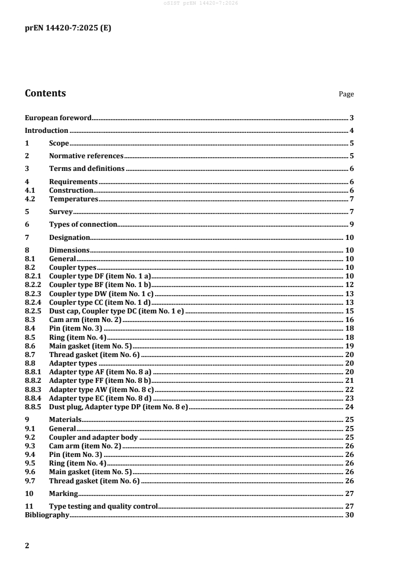
Contents Page
European foreword . 3
Introduction . 4
1 Scope . 5
2 Normative references . 5
3 Terms and definitions . 6
4 Requirements . 6
4.1 Construction . 6
4.2 Temperatures . 7
5 Survey . 7
6 Types of connection. 9
7 Designation. 10
8 Dimensions . 10
8.1 General . 10
8.2 Coupler types . 10
8.2.1 Coupler type DF (item No. 1 a). 10
8.2.2 Coupler type BF (item No. 1 b). 12
8.2.3 Coupler type DW (item No. 1 c) . 13
8.2.4 Coupler type CC (item No. 1 d) . 13
8.2.5 Dust cap, Coupler type DC (item No. 1 e) . 15
8.3 Cam arm (item No. 2) . 16
8.4 Pin (item No. 3) . 18
8.5 Ring (item No. 4) . 18
8.6 Main gasket (item No. 5) . 19
8.7 Thread gasket (item No. 6) . 20
8.8 Adapter types . 20
8.8.1 Adapter type AF (item No. 8 a) . 20
8.8.2 Adapter type FF (item No. 8 b). 21
8.8.3 Adapter type AW (item No. 8 c) . 22
8.8.4 Adapter type EC (item No. 8 d) . 23
8.8.5 Dust plug, Adapter type DP (item No. 8 e) . 24
9 Materials . 25
9.1 General . 25
9.2 Coupler and adapter body . 25
9.3 Cam arm (item No. 2) . 26
9.4 Pin (item No. 3) . 26
9.5 Ring (item No. 4) . 26
9.6 Main gasket (item No. 5) . 26
9.7 Thread gasket (item No. 6) . 26
10 Marking . 27
11 Type testing and quality control . 27
Bibliography . 30
prEN 14420-7:2025 (E)
European foreword
This document (prEN 14420-7:2025) has been prepared by Technical Committee CEN/TC 218 “Rubber
and plastics hoses and hose assemblies”, the secretariat of which is held by BSI.
This document is currently submitted to the CEN Enquiry.
This document will supersede EN 14420-7:2022/AC:2023.
prEN 14420-7:2025 includes the following significant technical changes with respect to EN 14420-7:
2022/AC:2023:
— for Figure 3, the symbol d6 have been deleted as d6 does not appear in the document;
— for Figure 6, the missing explanation for entry 1 have been included.
The EN 14420 series, Hose fittings with clamp units, consists of the following parts:
— Part 1: Requirements, types of fixing and connection, designation and testing
— Part 2: Hose side parts of hose tail
— Part 3: Clamp units, bolted or pinned
— Part 4: Flange connections
— Part 5: Threaded connections
— Part 6: TW tank truck couplings
— Part 7: Cam locking couplings
— Part 8: Symmetrical half coupling (Guillemin system)
prEN 14420-7:2025 (E)
Introduction
Cam locking couplings are manufactured worldwide according to the American “military specification”
MIL-C-27487, which fixes the coupling side in a limited way, but not the connection side. Other parts like
levers, bolts, ring and gaskets are not standardized.
prEN 14420-7:2025 (E)
1 Scope
This document specifies the design, materials, dimensions and marking requirements for cam locking
couplings that serve as the link between hoses and connections to transport liquids, solids and gases,
except liquid gas and steam.
For all sizes of aluminium cast material couplings and for all couplings of size DN 100, the pressure range
is from −0,8 bar to 10 bar in the working temperature range from −20 °C to +65 °C. All other couplings
according to this document are capable of operating within the pressure range from 0,8 bar to 16 bar in
the working temperature range from −20 °C to +65 °C.
2 Normative references
The following documents are referred to in the text in such a way that some or all of their content
constitutes requirements of this document. For dated references, only the edition cited applies. For
undated references, the latest edition of the referenced document (including any amendments) applies.
EN 755-2, Aluminium and aluminium alloys - Extruded rod/bar, tube and profiles - Part 2: Mechanical
properties
EN 1706, Aluminium and aluminium alloys - Castings - Chemical composition and mechanical properties
EN 1982, Copper and copper alloys - Ingots and castings
EN 10088-1, Stainless steels - Part 1: List of stainless steels
EN 10213, Steel castings for pressure purposes
EN 12420, Copper and copper alloys - Forgings
EN 14420-1:2013, Hose fittings with clamp units - Part 1: Requirements, types of fixing and connection,
designation and testing
EN 14420-2, Hose fittings with clamp units - Part 2: Hose side parts of hose tail
EN 14420-5, Hose fittings with clamp units - Part 5: Threaded connections
EN 22768-1, General tolerances - Part 1: Tolerances for linear and angular dimensions without individual
tolerance indications (ISO 2768-1)
EN 22768-2 , General tolerances - Part 2: Geometrical tolerances for features without individual tolerance
indications (ISO 2768-2)
EN ISO 8330, Rubber and plastics hoses and hose assemblies - Vocabulary (ISO 8330)
ISO 272, Fasteners — Hexagon products — Widths across flats
1 bar = 0,1 MPa.
EN 22768-2 has been withdrawn and replaced by EN ISO 22081.
prEN 14420-7:2025 (E)
3 Terms and definitions
For the purposes of this document, the terms and definitions given in EN ISO 8330 and the following
apply.
ISO and IEC maintain terminology databases for use in standardization at the following addresses:
— ISO Online browsing platform: available at https://www.iso.org/obp
— IEC Electropedia: available at https://www.electropedia.org/
3.1
DN
nominal size
alphanumeric designation of size for components of a pipework system, which is used for reference
purposes, comprised of the letters DN followed by a dimensionless whole number which is indirectly
related to the physical size, in millimetres, of the bore or outside diameter of the end connections
Note 1 to entry: The number following the letters DN does not represent a measurable value and is not be used
for calculation purposes except where specified in the relevant standard.
Note 2 to entry: In those standards which use the DN designation system, any relationship between DN and
component dimensions is to be indicated, e.g. DN/OD or DN/ID.
[SOURCE: EN ISO 6708:1995, 2.1, modified]
3.2
PN
alphanumeric designation used for reference purposes related to a combination of mechanical and
dimensional characteristics of a component of a hose fitting
Note 1 to entry: It comprises the letters PN followed by a dimensionless number.
Note 2 to entry: The number following the letters PN does not represent a measurable value and should not be
used for calculation purposes except where specified in the relevant standard.
3.3
main gasket
interface gasket between the male and female part of a coupling
3.4
thread gasket
flat faced gasket for threads according to EN ISO 228-1
4 Requirements
4.1 Construction
The curves of the lever and the adapters as well as the dimensions of the main gaskets shall be
harmonized such that twisting of the hose and vibrating during operation shall not lead to leakage. Cam
arms shall be manually operable.
Cam arms shall be suitable to operate without using tools.
For gauges for cam-locking couplings according to this document see Annex A.
prEN 14420-7:2025 (E)
NOTE If the requirements of this document are met, compatibility between couplers and adapters from
different manufacturers is ensured. Apart from gaskets, the interchangeability between spare parts from different
manufacturers cannot be ensured.
4.2 Temperatures
Range of working temperatures of couplings equipped with nitrile butadiene rubber gasket
(NBR-gasket): −20 °C to +65 °C.
5 Survey
Figure 1 and Figure 2 show examples for cam-locking couplings. A parts list is given in Table 1.
NOTE Chain optional.
Figure 1 — Coupler type DF and adapter type DP (dust plug)
prEN 14420-7:2025 (E)
NOTE Chain optional.
Figure 2 — Coupler type DC and ad
...