


ASTM G28-02(2015)
(Test Method)Standard Test Methods for Detecting Susceptibility to Intergranular Corrosion in Wrought, Nickel-Rich, Chromium-Bearing Alloys
Standard Test Methods for Detecting Susceptibility to Intergranular Corrosion in Wrought, Nickel-Rich, Chromium-Bearing Alloys
SIGNIFICANCE AND USE
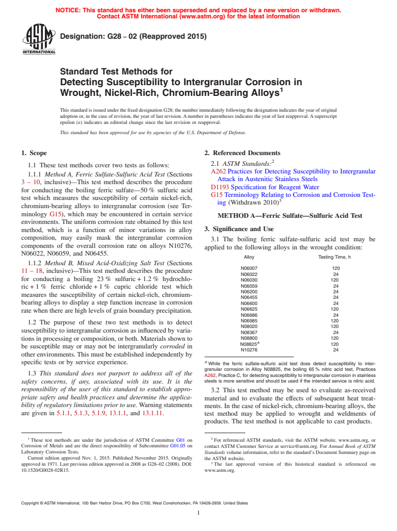
3.1 The boiling ferric sulfate-sulfuric acid test may be applied to the following alloys in the wrought condition:
Alloy
Testing Time, h
N06007
120
N06022
24
N06030
120
N06059
24
N06200
24
N06455
24
N06600
24
N06625
120
N06686
24
N06985
120
N08020
120
N08367
24
N08800
120
N08825A
120
N10276
24(A) While the ferric sulfate-sulfuric acid test does detect susceptibility to inter- granular corrosion in Alloy N08825, the boiling 65 % nitric acid test, Practices A262, Practice C, for detecting susceptibility to intergranular corrosion in stainless steels is more sensitive and should be used if the intended service is nitric acid.
3.2 This test method may be used to evaluate as-received material and to evaluate the effects of subsequent heat treatments. In the case of nickel-rich, chromium-bearing alloys, the test method may be applied to wrought and weldments of products. The test method is not applicable to cast products.
SCOPE
1.1 These test methods cover two tests as follows:
1.1.1 Method A, Ferric Sulfate-Sulfuric Acid Test (Sections 3 – 10, inclusive)—This test method describes the procedure for conducting the boiling ferric sulfate—50 % sulfuric acid test which measures the susceptibility of certain nickel-rich, chromium-bearing alloys to intergranular corrosion (see Terminology G15), which may be encountered in certain service environments. The uniform corrosion rate obtained by this test method, which is a function of minor variations in alloy composition, may easily mask the intergranular corrosion components of the overall corrosion rate on alloys N10276, N06022, N06059, and N06455.
1.1.2 Method B, Mixed Acid-Oxidizing Salt Test (Sections 11 – 18, inclusive)—This test method describes the procedure for conducting a boiling 23 % sulfuric + 1.2 % hydrochloric + 1 % ferric chloride + 1 % cupric chloride test which measures the susceptibility of certain nickel-rich, chromium-bearing alloys to display a step function increase in corrosion rate when there are high levels of grain boundary precipitation.
1.2 The purpose of these two test methods is to detect susceptibility to intergranular corrosion as influenced by variations in processing or composition, or both. Materials shown to be susceptible may or may not be intergranularly corroded in other environments. This must be established independently by specific tests or by service experience.
1.3 This standard does not purport to address all of the safety concerns, if any, associated with its use. It is the responsibility of the user of this standard to establish appropriate safety and health practices and determine the applicability of regulatory limitations prior to use. Warning statements are given in 5.1.1, 5.1.3, 5.1.9, 13.1.1, and 13.1.11.
General Information
Buy Standard
Standards Content (Sample)
NOTICE: This standard has either been superseded and replaced by a new version or withdrawn.
Contact ASTM International (www.astm.org) for the latest information
Designation: G28 − 02 (Reapproved 2015)
Standard Test Methods for
Detecting Susceptibility to Intergranular Corrosion in
Wrought, Nickel-Rich, Chromium-Bearing Alloys
ThisstandardisissuedunderthefixeddesignationG28;thenumberimmediatelyfollowingthedesignationindicatestheyearoforiginal
adoption or, in the case of revision, the year of last revision.Anumber in parentheses indicates the year of last reapproval.Asuperscript
epsilon (´) indicates an editorial change since the last revision or reapproval.
This standard has been approved for use by agencies of the U.S. Department of Defense.
1. Scope 2. Referenced Documents
2.1 ASTM Standards:
1.1 These test methods cover two tests as follows:
A262 Practices for Detecting Susceptibility to Intergranular
1.1.1 Method A, Ferric Sulfate-Sulfuric Acid Test (Sections
Attack in Austenitic Stainless Steels
3–10, inclusive)—This test method describes the procedure
D1193 Specification for Reagent Water
for conducting the boiling ferric sulfate—50 % sulfuric acid
G15 Terminology Relating to Corrosion and Corrosion Test-
test which measures the susceptibility of certain nickel-rich,
ing (Withdrawn 2010)
chromium-bearing alloys to intergranular corrosion (see Ter-
minology G15), which may be encountered in certain service
METHOD A—Ferric Sulfate—Sulfuric Acid Test
environments. The uniform corrosion rate obtained by this test
3. Significance and Use
method, which is a function of minor variations in alloy
composition, may easily mask the intergranular corrosion
3.1 The boiling ferric sulfate-sulfuric acid test may be
components of the overall corrosion rate on alloys N10276,
applied to the following alloys in the wrought condition:
N06022, N06059, and N06455.
Alloy Testing Time, h
1.1.2 Method B, Mixed Acid-Oxidizing Salt Test (Sections
N06007 120
11–18, inclusive)—This test method describes the procedure
N06022 24
for conducting a boiling 23 % sulfuric + 1.2 % hydrochlo-
N06030 120
N06059 24
ric+1% ferric chloride+1% cupric chloride test which
N06200 24
measures the susceptibility of certain nickel-rich, chromium-
N06455 24
bearing alloys to display a step function increase in corrosion N06600 24
N06625 120
rate when there are high levels of grain boundary precipitation.
N06686 24
N06985 120
1.2 The purpose of these two test methods is to detect
N08020 120
susceptibility to intergranular corrosion as influenced by varia-
N08367 24
N08800 120
tionsinprocessingorcomposition,orboth.Materialsshownto
A
N08825 120
be susceptible may or may not be intergranularly corroded in
N10276 24
other environments.This must be established independently by
A
specific tests or by service experience.
While the ferric sulfate-sulfuric acid test does detect susceptibility to inter-
granular corrosion in Alloy N08825, the boiling 65 % nitric acid test, Practices
1.3 This standard does not purport to address all of the
A262,PracticeC,fordetectingsusceptibilitytointergranularcorrosioninstainless
steels is more sensitive and should be used if the intended service is nitric acid.
safety concerns, if any, associated with its use. It is the
responsibility of the user of this standard to establish appro-
3.2 This test method may be used to evaluate as-received
priate safety and health practices and determine the applica-
material and to evaluate the effects of subsequent heat treat-
bilityofregulatorylimitationspriortouse.Warningstatements
ments. In the case of nickel-rich, chromium-bearing alloys, the
are given in 5.1.1, 5.1.3, 5.1.9, 13.1.1, and 13.1.11.
test method may be applied to wrought and weldments of
products. The test method is not applicable to cast products.
1 2
These test methods are under the jurisdiction of ASTM Committee G01 on For referenced ASTM standards, visit the ASTM website, www.astm.org, or
Corrosion of Metals and are the direct responsibility of Subcommittee G01.05 on contact ASTM Customer Service at service@astm.org. For Annual Book of ASTM
Laboratory Corrosion Tests. Standards volume information, refer to the standard’s Document Summary page on
Current edition approved Nov. 1, 2015. Published November 2015. Originally the ASTM website.
approved in 1971. Last previous edition approved in 2008 as G28–02 (2008). DOI: The last approved version of this historical standard is referenced on
10.1520/G0028-02R15. www.astm.org.
Copyright © ASTM International, 100 Barr Harbor Drive, PO Box C700, West Conshohocken, PA 19428-2959. United States
G28 − 02 (2015)
4. Apparatus 5.1.6 Lubricate the ground glass of the condenser joint with
silicone grease.
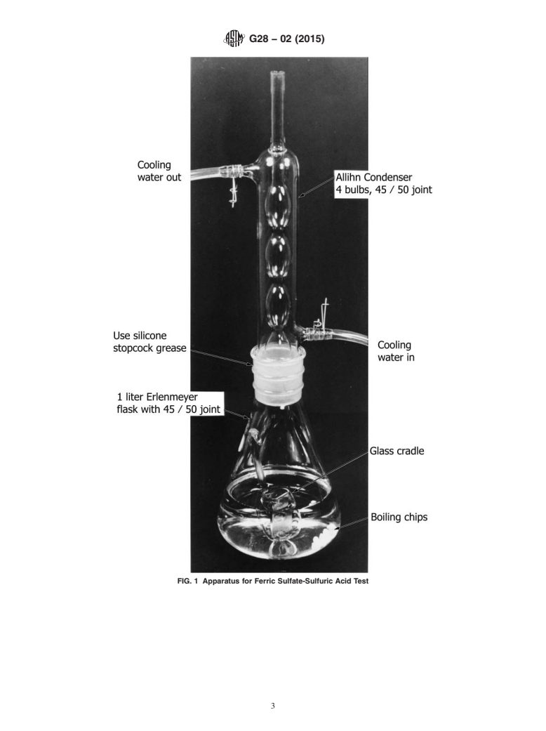
4.1 The apparatus (Note 1) is illustrated in Fig. 1.
4 5.1.7 Cover the flask with the condenser and circulate
4.1.1 Allihn or Soxhlet Condenser, 4-bulb, with a 45/50
cooling water.
ground-glass joint, overall length about 330 mm, condensing
5.1.8 Boil the solution until all ferric sulfate is dissolved.
section about 240 mm.
5.1.9 Warning—It has been reported that violent boiling
4.1.2 Erlenmeyer Flask, 1-L, with a 45/50 ground-glass
can occur resulting in acid spills. It is important to ensure that
joint. The ground-glass opening shall be 40 mm wide.
theconcentrationofaciddoesnotincreaseandthatanadequate
4.1.3 Glass Cradle (Fig. 2)—To pass through the ground-
number of boiling chips (which are resistant to attack by the
glass joint on the Erlenmeyer flask, the width of the cradle
test solution) are present.
should not exceed 40 mm and the front-to-back distance must
be such that the cradle will fit the 40-mm diameter opening. It
6. Test Specimens
should have three or four holes to increase circulation of the
test solution around the specimen (Note 2). 6.1 Aspecimen having a total surface area of 5 to 20 cm is
recommended.
NOTE 1—Substitution for this equipment may not be used. The
cold-finger type of standard Erlenmeyer flask may not be used.
6.2 The intent is to test a specimen representing as nearly as
NOTE 2—Other equivalent means of specimen support, such as glass
possible the material as used in service. The specimens should
hooks or stirrups, may also be used.
becuttorepresentthegrainflowdirectionthatwillseeservice,
4.1.4 Boiling Chips, or some other boiling aids must be
for example, specimens should not contain cross-sectional
used to prevent bumping.
areas unless it is the intent of the test to evaluate these. Only
4.1.5 Silicone Grease, (for example, stopcock grease) is
such surface finishing should be performed as is required to
recommended for the ground-glass joint.
remove foreign material and obtain a standard, uniform finish
4.1.6 Electrically Heated Hot Plate, or equivalent to pro-
as specified in 6.4. For very heavy sections, specimens should
vide heat for continuous boiling of the solution.
be maintained to represent the appropriate surface while
4.1.7 AnalyticalBalance,capableofweighingtothenearest
maintaining reasonable specimen size for convenience in
0.001 g.
testing. Ordinarily, removal of more material than necessary
will have little influence on the test results. However, in the
5. Test Solution
special case of surface decarburization or of carburization (the
latter is sometimes encountered in tubing when lubricants or
5.1 Prepare 600 mL of 50 % (49.4 to 50.9 %) solution as
binders containing carbonaceous materials are employed), it
follows:
may be possible by heavy grinding or machining to remove the
5.1.1 Warning—Protect the eyes and use rubber gloves for
affected layer completely. Such treatment of test specimens is
handling acid. Place the test flask under a hood.
not permissible, except in tests undertaken to demonstrate such
5.1.2 First, measure 400 mL of Type IV reagent water
surface effects.
(Specification D1193) in a 500-mL graduate and pour into the
flask.
6.3 When specimens are cut by shearing, the deformed
5.1.3 Then measure 236 mL of reagent-grade sulfuric acid
material must be removed by machining or grinding to a depth
(H SO ) of a concentration which must be in the range from
equal to the thickness of the specimen to remove cold worked
2 4
95.0to98.0weightpercentina250-mLgraduate.Addtheacid
metal.
slowly to the water in the flask to avoid boiling by the heat
6.4 All surfaces of the specimen, including edges, should be
evolved (Note 3). Externally cooling the flask with water
finished using wet No. 80-grit or dry No. 120-grit abrasive
during the mixing will also reduce overheating.
paper. If dry abrasive paper is used, polish slowly to avoid
NOTE 3—Loss of vapor results in concentration of the acid.
overheating. Sand blasting should not be used.
5.1.4 Weigh 25 g of reagent grade ferric sulfate (contains
6.5 Residual oxide scale has been observed to cause spuri-
about 75 % Fe (SO ) (Note 4)) and add to the H SO
ous specimen activation in the test solution. Therefore, the
2 4 3 2 4
solution. A trip balance may be used.
formation of oxide scale in stamped codes must be prevented,
and all traces of oxide scale formed during heat treatment must
NOTE 4—Ferritic sulfate is a specific additive that establishes and
be thoroughly removed prior to stamping identification codes.
controls the corrosion potential. Substitutions are not permitted.
6.6 Thespecimendimensionsshouldbemeasuredincluding
5.1.5 Add boiling chips.
the edges and inner surfaces of any holes and the total exposed
area calculated.
6.7 The specimen should then be degreased using suitable
To avoid frequent chipping of the drip-tip of the condenser during handling, the
modified condenser described by Streicher, M.A., and Sweet,A. J., Corrosion,Vol
nonchlorinated agents such as soap and acetone, dried, and
25, 1969, pp. 1, has been found suitable for this use.
then weighed to the nearest 0.001 g.
The sole source of supply of the apparatus known to the committee at this time
is amphoteric alundum Hengar Boiling Granules, available from Hengar Company,
a division of Henry Troemner, LLC, 201 Wolf Drive, Thorofare, NJ 08086. If you 7. Procedure
are aware of alternative suppliers, please provide this information to ASTM
7.1 Place the specimen in the glass cradle, remove the
International Headquarters. Your comments will receive careful consideration at a
meeting of the responsible technical committee, which you may attend. condenser, immerse the cradle by means of a hook in the
G28 − 02 (2015)
FIG. 1 Apparatus for Ferric Sulfate-Sulfuric Acid Test
G28 − 02 (2015)
FIG. 2 Glass Cradle
G28 − 02 (2015)
actively boiling solution (Fig. 1), and immediately replace the
micrometres per year (µm/y) 8.76 × 10
picometres per second (pm/s) 2.78 × 10
condenser. A fresh solution should be used for each test.
2 4 B
grams per square metre-hour (g/m -h) 1.00 × 10 ×D
6 B
7.2 Mark the liquid level on the flask with wax crayon to milligrams per square decimetre-day (mdd) 2.40 × 10 ×D
2 6 B
micrograms per square metre-second (µg/m -s) 2.78 × 10 ×D
provide a check on vapor loss which would result in concen-
tration of the acid. If there is an appreciable change in the level
A
Ifdesired,theseconstantsmayalsobeusedtoconvertcorrosionratesfromone
(a 0.5-cm or more drop), repeat the test with fresh solution and
set of units to another. To convert a corrosion rate in units Xtoarateinunits Y,
with a fresh specimen or a reground specimen. multiply by K /K . For example:
Y X
6 6
15mpy5153 fs2.78310 d/s3.45310 dg pm/s
7.3 Continue immersion of the specimen for the length of
512.1 pm/s
time specified in Section 3, then remove the specimen, rinse in
B
Density is not needed to calculate the corrosion rate in these units. The density
water and acetone, and dry.
in the constant K cancels out the density in the corrosion rate equation.
7.4 Weigh the specimen and subtract this mass from the
8.1.2
original mass.
UNS Designation Density, g/cm
7.5 Intermediate weighing is not necessary, except as noted
in 7.7. The tests can be run without interruption. However, if N06007 8.31
N06022 8.69
preliminaryresultsaredesired,thespecimencanberemovedat
N06030 8.22
any time for weighing.
N06059 8.80
N06200 8.50
7.6 Replacement of acid is not necessary during the test
N06455 8.64
periods.
N06600 8.41
N06625 8.44
7.7 IfthecorrosionrateisextraordinarilyhighinMethodA,
N06686 8.73
as evidenced by a change in color (green) of the solution, N06985 8.31
N08020 8.05
additional ferric sulfate must be added during the test. The
N08367 8.06
amount of ferric sulfate that must be added, if the total mass
N08800 8.03
N08825 8.14
loss of all specimens exceeds2gas indicated by an interme-
N10276 8.87
diate weight, is 10 g for each1gof dissolved alloy. This does
8.2 Interpretation of Results—The presence of intergranular
not apply to Method B.
corrosion is usually determined by comparing the calculated
7.8 In Method A, several specimens of the same alloy may
corrosion rate to that for properly annealed material. Even in
be tested simultaneously. The number (3 or 4) is limited only
the absence of intergranular corrosion, the rate of general or
by the number of glass cradles that can be fitted into the flask
grain-face corrosion of properly annealed material will vary
and the consumption of ferric sulfate. Only one sample should
from one alloy to another. These differences are demonstrated
be tested in a flask for Method B.
in Refs (1-7).
7.9 During testing, there is some deposition of iron oxides
8.3 As an alternative or in addition to calculating a corro-
on the upper part for the flask. This can be readily removed
sion rate from mass loss data, metallographic examination may
after test completion by boiling a solution of 10 % hydrochlo-
be used to evaluate the degree of intergranular corrosion. The
ric acid (HCl) in the flask.
depth of attack considered acceptable shall be determined
between buyer and seller.
8. Calculation and Interpretation of Results
8.1 Calculation—Measure the effect of the acid solution on
9. Report
the mat.
9.1 Record the test procedure used, specimen size and
Corrosion Rate 5 ~K 3W!/~A 3T 3D! (1)
surface preparation, time of test, temperature, and mass loss.
where:
9.2 Report following information:
K = a constant (see 8.1.1), 9.2.1 Alloy number and heat number,
T = time of exposure, h, to the nearest 0.01 h, 9.2.2 Chemical composition and thermal treatment,
2 2
A = area, cm , to the nearest 0.01 cm ,
9.2.3 Test method used, and
W = mass loss, g, to the nearest 0.001 g, and
9.2.4 Calculated corrosion rate in units desired.
D = density, g/cm (see 8.1.2).
10. Precision and Bias
8.1.1 Many different units are used to express corrosion
rates. Using the above units for T, A, W, and D, the corrosion 10.1 The precision of the procedure in Test Method A of
rate can be calculated in a variety of units with the following Test
...
This document is not an ASTM standard and is intended only to provide the user of an ASTM standard an indication of what changes have been made to the previous version. Because
it may not be technically possible to adequately depict all changes accurately, ASTM recommends that users consult prior editions as appropriate. In all cases only the current version
of the standard as published by ASTM is to be considered the official document.
Designation: G28 − 02 (Reapproved 2008) G28 − 02 (Reapproved 2015)
Standard Test Methods for
Detecting Susceptibility to Intergranular Corrosion in
Wrought, Nickel-Rich, Chromium-Bearing Alloys
This standard is issued under the fixed designation G28; the number immediately following the designation indicates the year of original
adoption or, in the case of revision, the year of last revision. A number in parentheses indicates the year of last reapproval. A superscript
epsilon (´) indicates an editorial change since the last revision or reapproval.
This standard has been approved for use by agencies of the U.S. Department of Defense.
1. Scope
1.1 These test methods cover two tests as follows:
1.1.1 Method A, Ferric Sulfate-Sulfuric Acid Test (Sections 3 – 10, inclusive)—This test method describes the procedure for
conducting the boiling ferric sulfate—50 % sulfuric acid test which measures the susceptibility of certain nickel-rich,
chromium-bearing alloys to intergranular corrosion (see Terminology G15), which may be encountered in certain service
environments. The uniform corrosion rate obtained by this test method, which is a function of minor variations in alloy
composition, may easily mask the intergranular corrosion components of the overall corrosion rate on alloys N10276, N06022,
N06059, and N06455.
1.1.2 Method B, Mixed Acid-Oxidizing Salt Test (Sections 11 – 18, inclusive)—This test method describes the procedure for
conducting a boiling 23 % sulfuric + 1.2 % hydrochloric + 1 % ferric chloride + 1 % cupric chloride test which measures the
susceptibility of certain nickel-rich, chromium-bearing alloys to display a step function increase in corrosion rate when there are
high levels of grain boundary precipitation.
1.2 The purpose of these two test methods is to detect susceptibility to intergranular corrosion as influenced by variations in
processing or composition, or both. Materials shown to be susceptible may or may not be intergranularly corroded in other
environments. This must be established independently by specific tests or by service experience.
1.3 This standard does not purport to address all of the safety concerns, if any, associated with its use. It is the responsibility
of the user of this standard to establish appropriate safety and health practices and determine the applicability of regulatory
limitations prior to use. Warning statements are given in 5.1.1, 5.1.3, 5.1.9, 13.1.1, and 13.1.11.
2. Referenced Documents
2.1 ASTM Standards:
A262 Practices for Detecting Susceptibility to Intergranular Attack in Austenitic Stainless Steels
D1193 Specification for Reagent Water
G15 Terminology Relating to Corrosion and Corrosion Testing (Withdrawn 2010)
METHOD A—Ferric Sulfate—Sulfuric Acid Test
3. Significance and Use
3.1 The boiling ferric sulfate-sulfuric acid test may be applied to the following alloys in the wrought condition:
Alloy Testing Time, h
N06007 120
N06022 24
N06030 120
N06059 24
These test methods are under the jurisdiction of ASTM Committee G01 on Corrosion of Metals and are the direct responsibility of Subcommittee G01.05 on Laboratory
Corrosion Tests.
Current edition approved May 1, 2008Nov. 1, 2015. Published May 2008November 2015. Originally approved in 1971. Last previous edition approved in 20022008 as
G28–02. –02 (2008). DOI: 10.1520/G0028-02R08.10.1520/G0028-02R15.
For referenced ASTM standards, visit the ASTM website, www.astm.org, or contact ASTM Customer Service at service@astm.org. For Annual Book of ASTM Standards
volume information, refer to the standard’s Document Summary page on the ASTM website.
The last approved version of this historical standard is referenced on www.astm.org.
Copyright © ASTM International, 100 Barr Harbor Drive, PO Box C700, West Conshohocken, PA 19428-2959. United States
G28 − 02 (2015)
N06200 24
N06455 24
N06600 24
N06625 120
N06686 24
N06985 120
N08020 120
N08367 24
N08800 120
A
N08825 120
N10276 24
A
While the ferric sulfate-sulfuric acid test does detect susceptibility to inter- granular corrosion in Alloy N08825, the boiling 65 % nitric acid test, Practices A262, Practice
C, for detecting susceptibility to intergranular corrosion in stainless steels is more sensitive and should be used if the intended service is nitric acid.
3.2 This test method may be used to evaluate as-received material and to evaluate the effects of subsequent heat treatments. In
the case of nickel-rich, chromium-bearing alloys, the test method may be applied to wrought and weldments of products. The test
method is not applicable to cast products.
4. Apparatus
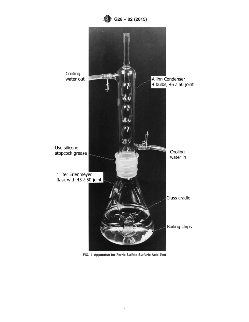
4.1 The apparatus (Note 1) is illustrated in Fig. 1.
4.1.1 Allihn or Soxhlet Condenser, 4-bulb, with a 45/50 ground-glass joint, overall length about 330 mm, condensing section
about 240 mm.
4.1.2 Erlenmeyer Flask, 1-L, with a 45/50 ground-glass joint. The ground-glass opening shall be 40 mm wide.
4.1.3 Glass Cradle (Fig. 2)—To pass through the ground-glass joint on the Erlenmeyer flask, the width of the cradle should not
exceed 40 mm and the front-to-back distance must be such that the cradle will fit the 40-mm diameter opening. It should have three
or four holes to increase circulation of the test solution around the specimen (Note 2).
NOTE 1—Substitution for this equipment may not be used. The cold-finger type of standard Erlenmeyer flask may not be used.
NOTE 2—Other equivalent means of specimen support, such as glass hooks or stirrups, may also be used.
4.1.4 Boiling Chips, or some other boiling aids must be used to prevent bumping.
4.1.5 Silicone Grease, (for example, stopcock grease) is recommended for the ground-glass joint.
4.1.6 Electrically Heated Hot Plate, or equivalent to provide heat for continuous boiling of the solution.
4.1.7 Analytical Balance, capable of weighing to the nearest 0.001 g.
5. Test Solution
5.1 Prepare 600 mL of 50 % (49.4 to 50.9 %) solution as follows:
5.1.1 Warning—Protect the eyes and use rubber gloves for handling acid. Place the test flask under a hood.
5.1.2 First, measure 400 mL of Type IV reagent water (Specification D1193) in a 500-mL graduate and pour into the flask.
5.1.3 Then measure 236 mL of reagent-grade sulfuric acid (H SO ) of a concentration which must be in the range from 95.0
2 4
to 98.0 weight percent in a 250-mL graduate. Add the acid slowly to the water in the flask to avoid boiling by the heat evolved
(Note 3). Externally cooling the flask with water during the mixing will also reduce overheating.
NOTE 3—Loss of vapor results in concentration of the acid.
5.1.4 Weigh 25 g of reagent grade ferric sulfate (contains about 75 % Fe (SO ) (Note 4)) and add to the H SO solution. A
2 4 3 2 4
trip balance may be used.
NOTE 4—Ferritic sulfate is a specific additive that establishes and controls the corrosion potential. Substitutions are not permitted.
5.1.5 Add boiling chips.
5.1.6 Lubricate the ground glass of the condenser joint with silicone grease.
5.1.7 Cover the flask with the condenser and circulate cooling water.
5.1.8 Boil the solution until all ferric sulfate is dissolved.
5.1.9 Warning—It has been reported that violent boiling can occur resulting in acid spills. It is important to ensure that the
concentration of acid does not increase and that an adequate number of boiling chips (which are resistant to attack by the test
solution) are present.
6. Test Specimens
6.1 A specimen having a total surface area of 5 to 20 cm is recommended.
To avoid frequent chipping of the drip-tip of the condenser during handling, the modified condenser described by Streicher, M. A., and Sweet, A. J., Corrosion, Vol 25,
1969, pp. 1, has been found suitable for this use.
The sole source of supply of the apparatus known to the committee at this time is amphoteric alundum Hengar Boiling Granules, available from Hengar Company, a
division of Henry Troemner, LLC, 201 Wolf Drive, Thorofare, NJ 08086. If you are aware of alternative suppliers, please provide this information to ASTM International
Headquarters. Your comments will receive careful consideration at a meeting of the responsible technical committee, which you may attend.
G28 − 02 (2015)
FIG. 1 Apparatus for Ferric Sulfate-Sulfuric Acid Test
G28 − 02 (2015)
FIG. 2 Glass Cradle
G28 − 02 (2015)
6.2 The intent is to test a specimen representing as nearly as possible the material as used in service. The specimens should be
cut to represent the grain flow direction that will see service, for example, specimens should not contain cross-sectional areas
unless it is the intent of the test to evaluate these. Only such surface finishing should be performed as is required to remove foreign
material and obtain a standard, uniform finish as specified in 6.4. For very heavy sections, specimens should be maintained to
represent the appropriate surface while maintaining reasonable specimen size for convenience in testing. Ordinarily, removal of
more material than necessary will have little influence on the test results. However, in the special case of surface decarburization
or of carburization (the latter is sometimes encountered in tubing when lubricants or binders containing carbonaceous materials
are employed), it may be possible by heavy grinding or machining to remove the affected layer completely. Such treatment of test
specimens is not permissible, except in tests undertaken to demonstrate such surface effects.
6.3 When specimens are cut by shearing, the deformed material must be removed by machining or grinding to a depth equal
to the thickness of the specimen to remove cold worked metal.
6.4 All surfaces of the specimen, including edges, should be finished using wet No. 80-grit or dry No. 120-grit abrasive paper.
If dry abrasive paper is used, polish slowly to avoid overheating. Sand blasting should not be used.
6.5 Residual oxide scale has been observed to cause spurious specimen activation in the test solution. Therefore, the formation
of oxide scale in stamped codes must be prevented, and all traces of oxide scale formed during heat treatment must be thoroughly
removed prior to stamping identification codes.
6.6 The specimen dimensions should be measured including the edges and inner surfaces of any holes and the total exposed area
calculated.
6.7 The specimen should then be degreased using suitable nonchlorinated agents such as soap and acetone, dried, and then
weighed to the nearest 0.001 g.
7. Procedure
7.1 Place the specimen in the glass cradle, remove the condenser, immerse the cradle by means of a hook in the actively boiling
solution (Fig. 1), and immediately replace the condenser. A fresh solution should be used for each test.
7.2 Mark the liquid level on the flask with wax crayon to provide a check on vapor loss which would result in concentration
of the acid. If there is an appreciable change in the level (a 0.5-cm or more drop), repeat the test with fresh solution and with a
fresh specimen or a reground specimen.
7.3 Continue immersion of the specimen for the length of time specified in Section 3, then remove the specimen, rinse in water
and acetone, and dry.
7.4 Weigh the specimen and subtract this mass from the original mass.
7.5 Intermediate weighing is not necessary, except as noted in 7.7. The tests can be run without interruption. However, if
preliminary results are desired, the specimen can be removed at any time for weighing.
7.6 Replacement of acid is not necessary during the test periods.
7.7 If the corrosion rate is extraordinarily high in Method A, as evidenced by a change in color (green) of the solution, additional
ferric sulfate must be added during the test. The amount of ferric sulfate that must be added, if the total mass loss of all specimens
exceeds 2 g as indicated by an intermediate weight, is 10 g for each 1 g of dissolved alloy. This does not apply to Method B.
7.8 In Method A, several specimens of the same alloy may be tested simultaneously. The number (3 or 4) is limited only by
the number of glass cradles that can be fitted into the flask and the consumption of ferric sulfate. Only one sample should be tested
in a flask for Method B.
7.9 During testing, there is some deposition of iron oxides on the upper part for the flask. This can be readily removed after
test completion by boiling a solution of 10 % hydrochloric acid (HCl) in the flask.
8. Calculation and Interpretation of Results
8.1 Calculation—Measure the effect of the acid solution on the mat.
Corrosion Rate 5 ~K 3W!/~A 3T 3D! (1)
where:
K = a constant (see 8.1.1),
T = time of exposure, h, to the nearest 0.01 h,
2 2
A = area, cm , to the nearest 0.01 cm ,
W = mass loss, g, to the nearest 0.001 g, and
D = density, g/cm (see 8.1.2).
8.1.1 Many different units are used to express corrosion rates. Using the above units for T, A, W, and D, the corrosion rate can
be calculated in a variety of units with the following appropriate value of K:
G28 − 02 (2015)
Constant K in Corrosion Rate
Corrosion Rate Units Desired
A
Equation
mils per year (mpy) 3.45 × 10
inches per year (ipy) 3.45 × 10
inches per month (ipm) 2.87 × 10
millimeters per year (mm/Y) 8.76 × 10
millimetres per year (mm/Y) 8.76 × 10
micrometers per year (μm/y) 8.76 × 10
micrometres per year (μm/y) 8.76 × 10
picometers per second (pm/s) 2.78 × 10
picometres per second (pm/s) 2.78 × 10
2 4 B
grams per square meter-hour (g/m -h) 1.00 × 10 × D
2 4 B
grams per square metre-hour (g/m -h) 1.00 × 10 × D
6 B
milligrams per square decimeter-day (mdd) 2.40 × 10 × D
6 B
milligrams per square decimetre-day (mdd) 2.40 × 10 × D
2 6 B
micrograms per square meter-second (μg/m -s) 2.78 × 10 × D
2 6 B
micrograms per square metre-second (μg/m -s) 2.78 × 10 × D
A
If desired, these constants may also be used to convert corrosion rates from one set of units to another. To convert a corrosion rate in units X to a rate in units Y, multiply
by K /K . For example:
Y X
6 6
15 mpy 515 3fs2.78 310 d/s3.45 310 dg pm/s
512.1 pm/s
B
Density is not needed to calculate the corrosion rate in these units. The density in the constant K cancels out the density in the corrosion rate equation.
8.1.2
UNS Designation Density, g/cm
N06007 8.31
N06022 8.69
N06030 8.22
N06059 8.80
N06200 8.50
N06455 8.64
N06600 8.41
N06625 8.44
N06686 8.73
N06985 8.31
N08020 8.05
N08367 8.06
N08
...
Questions, Comments and Discussion
Ask us and Technical Secretary will try to provide an answer. You can facilitate discussion about the standard in here.