

ISO 1099
(Main)Metallic materials — Fatigue testing — Axial force-controlled method
General Information
- Abstract
ISO 1099:2017 specifies the conditions for conducting axial, constant-amplitude, force-controlled, fatigue tests at ambient temperature on metallic specimens, without deliberately introduced stress concentrations. The object of testing while employing this document is to provide fatigue information, such as the relation between applied stress and number of cycles to failure for a given material condition, such as hardness and microstructure, at various stress ratios. While the form, preparation and testing of specimens of circular and rectangular cross-section are described, component testing and other specialized forms of testing are not included in this document.
- Status
- Not Published
- Technical Committee
- ISO/TC 164/SC 4 - Fatigue, fracture and toughness testing
- Drafting Committee
- ISO/TC 164/SC 4 - Fatigue, fracture and toughness testing
- Current Stage
- 6000 - International Standard under publication
- Start Date
- 03-Sep-2026
- Completion Date
- 05-Sep-2026
Buy Documents
ISO/FDIS 1099 - Metallic materials — Fatigue testing — Axial force-controlled method
REDLINE ISO/FDIS 1099 - Metallic materials — Fatigue testing — Axial force-controlled method
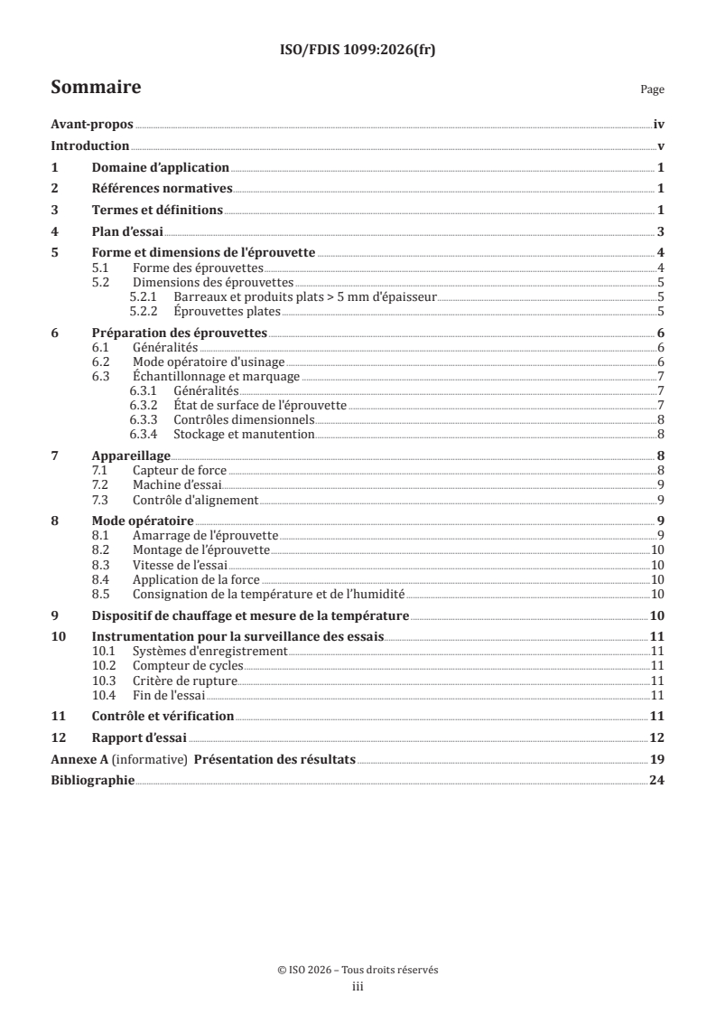
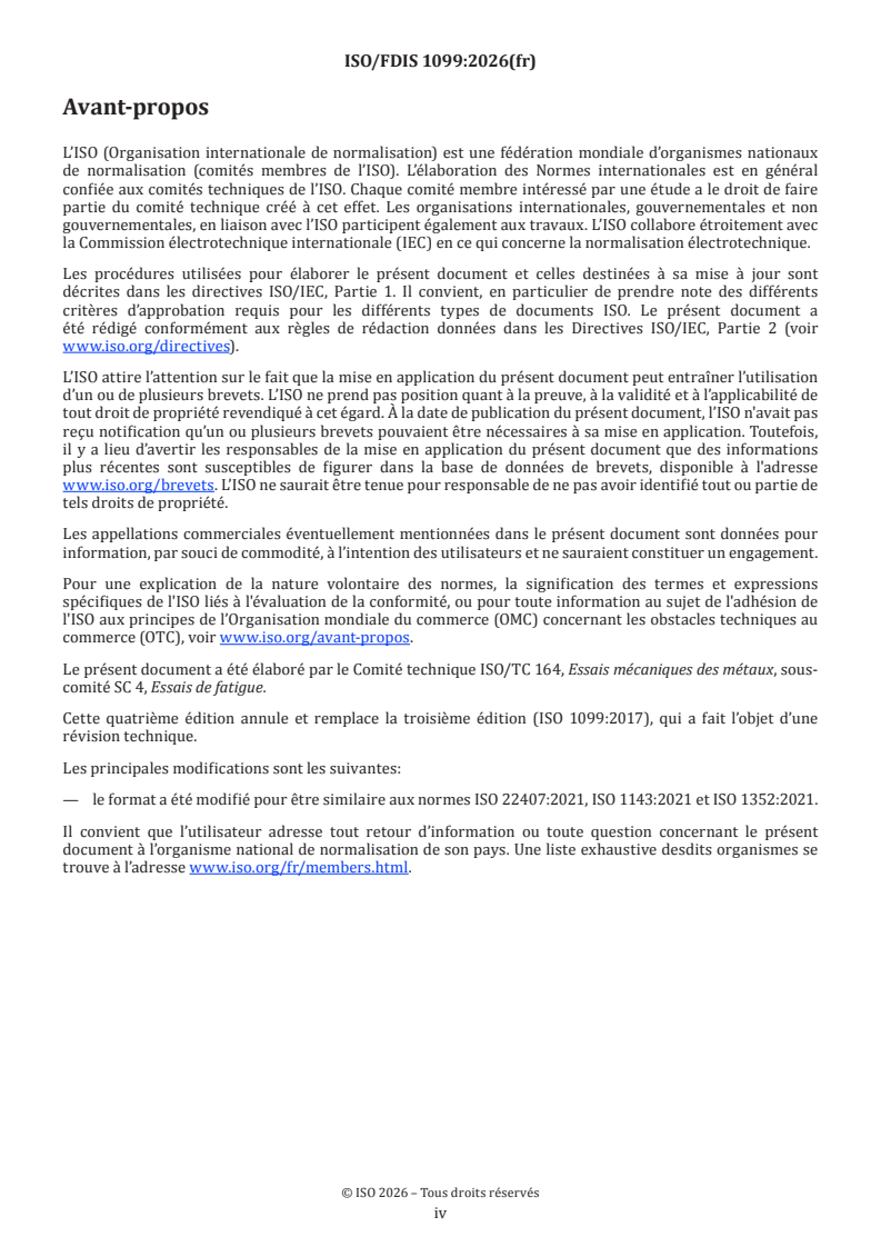
ISO/FDIS 1099 - Matériaux métalliques — Essais de fatigue — Méthode par force axiale contrôlée
Overview
ISO 1099:2017 - Metallic materials - Fatigue testing - Axial force-controlled method - is an international standard published by ISO that defines the method for performing axial, constant-amplitude, force-controlled fatigue tests on metallic specimens at ambient temperatures. This standard is essential for generating reliable and reproducible fatigue data, particularly the relationship between applied stress and the number of cycles to failure for metals under different material conditions, such as hardness and microstructure. ISO 1099 focuses exclusively on specimen-level testing, specifically for specimens with circular or rectangular cross-sections, and does not cover component or specialized testing.
Key Topics
- Axial Force-Controlled Fatigue Testing: Details the requirements for conducting fatigue tests where the axial force is maintained at a constant amplitude, simulating cyclic loading conditions often encountered in real-world applications.
- Test Specimen Preparation: Describes the form, machining, and dimensions required for test specimens to ensure consistency, including guidelines for both circular and rectangular cross-sections.
- Test Conditions: Specifies environmental conditions, primarily tests at ambient temperature (typically 10 °C to 35 °C), with notes about humidity and the need to avoid phase changes in the tested metal's microstructure.
- Testing Apparatus: Outlines requirements for the testing machines and force transducers, as well as alignment verification to ensure accurate force application along the specimen's longitudinal axis.
- Test Procedures: Includes guidelines on gripping and mounting specimens, setting test rates, applying force, temperature/humidity monitoring, and criteria for test termination (either at specimen failure or after a specified cycle count).
- Data Presentation: Provides recommendations for documenting results, including creating Wöhler (S-N) curves and mean stress diagrams, which are critical for engineering analysis and fatigue life prediction.
Applications
ISO 1099 plays a pivotal role in several fields, including:
- Material Development and Quality Control: Provides manufacturers, laboratories, and material scientists with standardized procedures for evaluating the fatigue strength and life of metallic materials, supporting development of new alloys and verification of batch consistency.
- Engineering Design and Analysis: Enables engineers to select appropriate materials and establish design limits for components subjected to cyclic loading, reducing the risk of fatigue failure in industries such as automotive, aerospace, and civil engineering.
- Research and Standardization: Used in academic and industrial research to compare fatigue properties across different metals, processing methods, and microstructural conditions.
- Regulatory Compliance: Often referenced in industry codes and product standards to ensure that metallic materials meet performance and safety criteria under cyclic stresses.
Related Standards
ISO 1099 is part of a framework of international standards on fatigue testing and mechanical characterization of metals. Relevant and complementary standards include:
- ISO 4965-1: Metallic materials - Dynamic force calibration for uniaxial fatigue testing - Part 1: Testing systems
- ISO 7500-1: Metallic materials - Calibration and verification of static uniaxial testing machines - Part 1: Tension/compression testing
- ISO 23788: Metallic materials - Verification of the alignment of fatigue testing machines
These standards, together with ISO 1099, help establish a robust foundation for reliable testing, analysis, and reporting of metallic materials' fatigue behavior according to globally recognized best practices.
Keywords: ISO 1099, fatigue testing, metallic materials, axial force-controlled, S-N curve, Wöhler curve, cyclic loading, material strength, test specimens, engineering standards, material characterization, quality control.
Relations
- Effective Date
- 08-Oct-2022
Buy Documents
ISO/FDIS 1099 - Metallic materials — Fatigue testing — Axial force-controlled method
REDLINE ISO/FDIS 1099 - Metallic materials — Fatigue testing — Axial force-controlled method
ISO/FDIS 1099 - Matériaux métalliques — Essais de fatigue — Méthode par force axiale contrôlée
Get Certified
Connect with accredited certification bodies for this standard

Element Materials Technology
Materials testing and product certification.

Inštitut za kovinske materiale in tehnologije
Institute of Metals and Technology. Materials testing, metallurgical analysis, NDT.
Sponsored listings
Frequently Asked Questions
ISO 1099 is a draft published by the International Organization for Standardization (ISO). Its full title is "Metallic materials — Fatigue testing — Axial force-controlled method". This standard covers: ISO 1099:2017 specifies the conditions for conducting axial, constant-amplitude, force-controlled, fatigue tests at ambient temperature on metallic specimens, without deliberately introduced stress concentrations. The object of testing while employing this document is to provide fatigue information, such as the relation between applied stress and number of cycles to failure for a given material condition, such as hardness and microstructure, at various stress ratios. While the form, preparation and testing of specimens of circular and rectangular cross-section are described, component testing and other specialized forms of testing are not included in this document.
ISO 1099:2017 specifies the conditions for conducting axial, constant-amplitude, force-controlled, fatigue tests at ambient temperature on metallic specimens, without deliberately introduced stress concentrations. The object of testing while employing this document is to provide fatigue information, such as the relation between applied stress and number of cycles to failure for a given material condition, such as hardness and microstructure, at various stress ratios. While the form, preparation and testing of specimens of circular and rectangular cross-section are described, component testing and other specialized forms of testing are not included in this document.
ISO 1099 is classified under the following ICS (International Classification for Standards) categories: 77.040.10 - Mechanical testing of metals. The ICS classification helps identify the subject area and facilitates finding related standards.
ISO 1099 has the following relationships with other standards: It is inter standard links to ISO 1099:2017. Understanding these relationships helps ensure you are using the most current and applicable version of the standard.
ISO 1099 is available in PDF format for immediate download after purchase. The document can be added to your cart and obtained through the secure checkout process. Digital delivery ensures instant access to the complete standard document.
Standards Content (Sample)
FINAL DRAFT
International
Standard
ISO/FDIS 1099
ISO/TC 164/SC 4
Metallic materials — Fatigue testing
Secretariat: ANSI
— Axial force-controlled method
Voting begins on:
Matériaux métalliques — Essais de fatigue — Méthode par force 2026-07-08
axiale contrôlée
Voting terminates on:
2026-09-02
RECIPIENTS OF THIS DRAFT ARE INVITED TO SUBMIT,
WITH THEIR COMMENTS, NOTIFICATION OF ANY
RELEVANT PATENT RIGHTS OF WHICH THEY ARE AWARE
AND TO PROVIDE SUPPOR TING DOCUMENTATION.
IN ADDITION TO THEIR EVALUATION AS
BEING ACCEPTABLE FOR INDUSTRIAL, TECHNO
LOGICAL, COMMERCIAL AND USER PURPOSES, DRAFT
INTERNATIONAL STANDARDS MAY ON OCCASION HAVE
TO BE CONSIDERED IN THE LIGHT OF THEIR POTENTIAL
TO BECOME STAN DARDS TO WHICH REFERENCE MAY BE
MADE IN NATIONAL REGULATIONS.
Reference number
ISO/FDIS 1099:2026(en) © ISO 2026
FINAL DRAFT
ISO/FDIS 1099:2026(en)
International
Standard
ISO/FDIS 1099
ISO/TC 164/SC 4
Metallic materials — Fatigue testing
Secretariat: ANSI
— Axial force-controlled method
Voting begins on:
Matériaux métalliques — Essais de fatigue — Méthode par force
axiale contrôlée
Voting terminates on:
RECIPIENTS OF THIS DRAFT ARE INVITED TO SUBMIT,
WITH THEIR COMMENTS, NOTIFICATION OF ANY
RELEVANT PATENT RIGHTS OF WHICH THEY ARE AWARE
AND TO PROVIDE SUPPOR TING DOCUMENTATION.
© ISO 2026
IN ADDITION TO THEIR EVALUATION AS
All rights reserved. Unless otherwise specified, or required in the context of its implementation, no part of this publication may
BEING ACCEPTABLE FOR INDUSTRIAL, TECHNO
LOGICAL, COMMERCIAL AND USER PURPOSES, DRAFT
be reproduced or utilized otherwise in any form or by any means, electronic or mechanical, including photocopying, or posting on
INTERNATIONAL STANDARDS MAY ON OCCASION HAVE
the internet or an intranet, without prior written permission. Permission can be requested from either ISO at the address below
TO BE CONSIDERED IN THE LIGHT OF THEIR POTENTIAL
or ISO’s member body in the country of the requester.
TO BECOME STAN DARDS TO WHICH REFERENCE MAY BE
MADE IN NATIONAL REGULATIONS.
ISO copyright office
CP 401 • Ch. de Blandonnet 8
CH-1214 Vernier, Geneva
Phone: +41 22 749 01 11
Email: copyright@iso.org
Website: www.iso.org
Published in Switzerland Reference number
ISO/FDIS 1099:2026(en) © ISO 2026
ii
ISO/FDIS 1099:2026(en)
Contents Page
Foreword .iv
Introduction .v
1 Scope . 1
2 Normative references . 1
3 Terms and definitions . 1
4 Test plan . 3
5 Specimen shape and dimensions . 4
5.1 Form of specimens .4
5.2 Dimension of specimens .4
5.2.1 Bars and flat sheets > 5 mm thick .4
5.2.2 Flat sheets.5
6 Preparation of specimens . 6
6.1 General .6
6.2 Machining procedure .6
6.3 Sampling and marking . .7
6.3.1 General .7
6.3.2 Surface condition of the specimen.7
6.3.3 Dimensional checks .7
6.3.4 Storage and handling .8
7 Apparatus . 8
7.1 Force transducer .8
7.2 Test machine .8
7.3 Alignment check .9
8 Procedure . 9
8.1 Gripping of specimen .9
8.2 Mounting of specimen .9
8.3 Rate of testing .9
8.4 Application of force .10
8.5 Recording of temperature and humidity .10
9 Heating device and temperature measurement . 10
10 Instrumentation for test monitoring .10
10.1 Recording systems .10
10.2 Cycle counter .10
10.3 Criterion of failure .10
10.4 Test termination .10
11 Checking and verification .11
12 Test report .11
Annex A (informative) Presentation of results .18
Bibliography .23
iii
ISO/FDIS 1099:2026(en)
Foreword
ISO (the International Organization for Standardization) is a worldwide federation of national standards
bodies (ISO member bodies). The work of preparing International Standards is normally carried out through
ISO technical committees. Each member body interested in a subject for which a technical committee
has been established has the right to be represented on that committee. International organizations,
governmental and non-governmental, in liaison with ISO, also take part in the work. ISO collaborates closely
with the International Electrotechnical Commission (IEC) on all matters of electrotechnical standardization.
The procedures used to develop this document and those intended for its further maintenance are described
in the ISO/IEC Directives, Part 1. In particular, the different approval criteria needed for the different types
of ISO document should be noted. This document was drafted in accordance with the editorial rules of the
ISO/IEC Directives, Part 2 (see www.iso.org/directives).
ISO draws attention to the possibility that the implementation of this document may involve the use of (a)
patent(s). ISO takes no position concerning the evidence, validity or applicability of any claimed patent
rights in respect thereof. As of the date of publication of this document, ISO had not received notice of (a)
patent(s) which may be required to implement this document. However, implementers are cautioned that
this may not represent the latest information, which may be obtained from the patent database available at
www.iso.org/patents. ISO shall not be held responsible for identifying any or all such patent rights.
Any trade name used in this document is information given for the convenience of users and does not
constitute an endorsement.
For an explanation of the voluntary nature of standards, the meaning of ISO specific terms and expressions
related to conformity assessment, as well as information about ISO's adherence to the World Trade
Organization (WTO) principles in the Technical Barriers to Trade (TBT), see www.iso.org/iso/foreword.html.
This document was prepared by Technical Committee ISO/TC 164, Mechanical testing of metals, Subcommittee
SC 4, Fatigue testing.
This fourth edition cancels and replaces the third edition (ISO 1099:2017), which has been technically
revised.
The main changes are as follows:
— format has been changed to be similar to ISO 22407:2021, ISO 1143:2021 and ISO 1352:2021.
Any feedback or questions on this document should be directed to the user’s national standards body. A
complete listing of these bodies can be found at www.iso.org/members.html.
iv
ISO/FDIS 1099:2026(en)
Introduction
This document is intended to provide guidance for conducting axial, constant-amplitude, force-controlled,
cyclic fatigue tests on specimens of a metal for the sake of generating fatigue-life data (i.e. stress vs. cycles to
failure) for material characterization.
Nominally identical specimens are mounted in an axial force-type fatigue-testing machine and subjected
to the required cyclic force conditions that introduce any one of the types of cyclic stress as illustrated in
Figure 1. The test waveform should be of constant amplitude and sinusoidal unless otherwise specified.
The force being applied to the specimen is along the longitudinal axis passing through the centroid of each
cross-section. The test is continued until the specimen fails or until a predetermined number of stress cycles
have been exceeded (see Clauses 4 and 10). Tests are typically conducted at ambient temperature (ideally
between 10 °C to 35 °C).
NOTE The results of a fatigue test can be affected by atmospheric conditions and where controlled conditions are
required, ISO 554:1976, 2.1 applies.
Caution should be taken regarding the selected test temperature of such isothermal testing so that there are
no possible phase changes in the material's microstructure. At elevated temperature creep phenomena can
occur. It is recommended to maintain the test temperature, T, at ≤ 0,3 of the melting temperature, T , of the
m
material being tested, i.e. the homologous temperature defined as: T = T(K)/T (K).
h m
v
FINAL DRAFT International Standard ISO/FDIS 1099:2026(en)
Metallic materials — Fatigue testing — Axial force-controlled
method
WARNING — This document calls for the use of substances and/or procedures that can be injurious
to health if adequate safety measures are not taken. This document does not address any health
hazards, safety or environmental matters associated with its use. It is the responsibility of the user
of this document to establish appropriate health, safety and environmentally acceptable practices.
1 Scope
This document specifies the conditions for conducting axial, constant-amplitude, force-controlled, fatigue
tests at ambient, elevated, and low temperature on metallic specimens, without deliberately introduced
stress concentrations. The object of testing while employing this document is to provide fatigue information,
such as the relation between applied stress and number of cycles to failure for a given material condition,
such as hardness and microstructure, at various stress ratios.
While the form, preparation and testing of specimens of circular and rectangular cross-section are
described, component testing and other specialized forms of testing are not included in this document.
NOTE 1 Fatigue tests on notched specimens are not covered by this document since the shape and size of notched
test pieces have not been standardized. However, fatigue-test procedures described in this document can be applied to
fatigue tests of such notched specimens.
NOTE 2 Throughout this document, the engineering stress is employed. Engineering stress is equal to the axially
applied force divided by the cross-sectional area of the test specimen, S = Force/Area, [MPa], at the test temperature.
2 Normative references
The following documents are referred to in the text in such a way that some or all of their content constitutes
requirements of this document. For dated references, only the edition cited applies. For undated references,
the latest edition of the referenced document (including any amendments) applies.
ISO 7500-1, Metallic materials — Calibration and verification of static uniaxial testing machines — Part 1:
Tension/compression testing machines — Calibration and verification of the force-measuring system
ISO 23788, Metallic materials — Verification of the alignment of fatigue testing machines
3 Terms and definitions
For the purposes of this document, the following terms and definitions apply.
ISO and IEC maintain terminology databases for use in standardization at the following addresses:
— ISO Online browsing platform: available at https:// www .iso .org/ obp
— IEC Electropedia: available at https:// www .electropedia .org/
3.1
test specimen diameter
d
diametric distance or width of the specimen or test piece where the stress is at a maximum
ISO/FDIS 1099:2026(en)
3.2
grip diameter
D
diameter of the specimen at grip end
3.3
thickness of test section
t
thickness of reduced section of rectangular test specimen
3.4
width of test section
w
width of reduced section of rectangular test specimen
3.5
parallel length
L
c
length in the gauge test section of a specimen or test piece that has equal testspecimen diameter (3.1) or
width oftest section (3.4) and is parallel
3.6
specimen length
L
z
overall length of test specimen
3.7
fillet radius
r
radius between the parallel length and the grip end of test specimen
Note 1 to entry: The curve need not be a true arc of a circle over the whole of the distance between the end of the
parallel length and the start of the grip end.
3.8
maximum stress
S
max
greatest algebraic value of stress in a stress cycle (3.14)
Note 1 to entry: See Figure 2.
3.9
mean stress
S
m
one-half the algebraic sum of the maximum stress (3.8) and the minimum stress (3.10) in a stress cycle (3.14)
Note 1 to entry: See Figure 2.
3.10
minimum stress
S
min
least algebraic value of stress in a stress cycle (3.14)
Note 1 to entry: See Figure 2.
3.11
stress amplitude
S
a
one-half the algebraic difference between the maximum stress (3.8) and the minimum stress (3.10)
Note 1 to entry: See Figure 2.
ISO/FDIS 1099:2026(en)
3.12
stress range
ΔS
a
algebraic difference between the maximum stress (3.8) and the minimum stress (3.10)
ΔS = S – S
a max min
Note 1 to entry: See Figure 2.
3.13
stress ratio
R
ratio of minimum to maximum stress (3.8) during any single cycle of fatigue operation
R = S /S
min max
Note 1 to entry: See Figure 2.
3.14
stress cycle
variation of stress with time, repeated periodically and identically
Note 1 to entry: See Figure 2.
3.15
number of cycles
N
number of smallest segments of the force-time, stress-time, etc.; function that is repeated periodically
3.16
fatigue life
N
f
number of applied cycles to achieve a defined failure criterion
3.17
fatigue strength at N cycles
S
N
value of the stress amplitude at a stated stress ratio under which the specimen would have a life of N cycles
4 Test plan
Before commencing testing, the following shall be agreed by the parties concerned, unless specified
otherwise in the relevant product standard:
a) the form of specimen to be used (see 5.1);
b) the R-ratio(s) to be used;
c) the objective of the tests, i.e. which of the following is to be determined:
1) the fatigue life at a specified stress amplitude;
2) the fatigue strength at specified fatigue cycles (N cycles), S ; i.e. fatigue limit to a fixed number of
N
cycles (e.g. 2 million to 10 million);
3) a full Wöhler or S-N curve.
d) the number of specimens to be tested and the testing sequence;
e) the number of cycles at which a test on an unfailed specimen shall be terminated;
ISO/FDIS 1099:2026(en)
f) the testing temperature if different from the requirements given in Clause 9.
In the light of recent research, it is of importance to note that metals generally do not exhibit an “endurance
limit” per se, that is, a stress below which the metal will endure an “infinite number of cycles without
failure.” Typically, the “plateau(s)” in stress-life is referred to as the conventional “fatigue limit(s) at a fixed
number of cycles”, but failures below these levels have been reported and do occur particularly in the long-
life regime where micro discontinuities govern behaviour. See, for example, References [10] to [13].
5 Specimen shape and dimensions
5.1 Form of specimens
Generally, a specimen having a fully machined test section is of the type shown in Figure 3 for a smooth
cylindrical-type gauge section.
The specimens can be of the following:
— circular cross-section with tangentially blending fillets between the test section and the ends, or with a
continuous radius between the ends (i.e. hourglass specimen);
— rectangular cross-section of uniform thickness over the test section with tangentially blending fillets
between the test section and the gripped ends (see Figure 4).
Specimens commonly known as hourglass specimens are discouraged since such designs have a continuous
radius between grip ends with a minimum diameter or width of the test section centrally located between
these ends for cylindrical and flat specimens respectively. Unlike a smooth, constant diameter or constant
width, in the gauge section where a known volume of material is equally under a uniaxial stress, the
hourglass specimen permits sampling of only a thin planar element of material at the minimum cross-
section. Thus, the fatigue results produced using such specimen designs cannot represent the response of the
bulk material where, particularly in the long-life fatigue regime, inclusions and other micro discontinuities
[10-13]
govern behaviour and there is a duality in crack initiation from surface to subsurface. In fact, such
results can be non-conservative particularly in the longer life regime where the largest micro discontinuity
cannot lie in the planar section of greatest stress.
It is important to note that for specimens of rectangular cross-section, it can be necessary to reduce the test
section in both width and thickness. If this is necessary, then blending fillets are required in both the width
and thickness directions. Also, for a rectangular-section specimen, where it is desired to take account of the
surface condition in which the metal will be used in actual application, then at least one surface of the test
section of the test piece should remain unmachined. It is often the case, for fatigue tests conducted using a
rectangular-section piece, that the results are not always comparable to those determined on cylindrical
specimens because of the difficulty in obtaining an adequate surface finish or because fatigue cracks initiate
preferentially at the corners of the rectangular test piece.
5.2 Dimension of specimens
5.2.1 Bars and flat sheets > 5 mm thick
The gauge portion of the specimen in a fatigue test represents a volume element of the material under study.
This implies the geometry of the specimen shall not affect the use of the test results.
This geometry shall fulfil the following conditions:
— provide a uniform cylindrical gauge portion;
— minimize the risk of buckling in compression;
— provide a uniform stress (strain) distribution over the whole gauge portion.
ISO/FDIS 1099:2026(en)
There shall be no undercutting due to machining of the parallel length at the transition radii or elsewhere on
the gauge section. This feature may be checked with an optical comparator at reasonable magnification (i.e.
~10 to 25X) to ensure this is true.
Taking into account these requirements, the experience gained by many laboratories and the results of
calculations taken from different types of specimens (see References [15] to [24]), the following geometric
dimensions (see Figure 3) are recommended:
a) diameter of cylindrical gauge length: 5 mm ≤ d ≤ 10 mm
b) parallel length: L ≥ 2d
c
c) transition radius (from parallel length to grip end): r ≥ 2d
d) diameter of grip end: D ≥ 2d
Other geometric cross-sections and gauge lengths may be used for specimens provided that uniform
distribution of stress in the gauge length is ensured.
The following end connections should be used:
— smooth cylindrical connection (with hydraulic jaws);
— button-end connection.
The test fixture should locate the specimen, provide axial alignment and exclude backlash. Design of the test
fixture will depend on the specimen end details. Several examples are given in Figure 5.
Designs of fatigue specimens in which alignment can depend on screw threads should not be recommended.
5.2.2 Flat sheets
5.2.2.1 General
In general, the considerations discussed in 5.2.1 also apply to tests on flat sheet products. However, these
tests require specific geometries and fixtures to avoid problems of buckling.
Because low forces are generally applied, more sensitive force transducers than usual can be required. The
gripping system can necessitate the use of flat mechanical or hydraulic jaws. However, with the latter type
of assembly it is difficult to ensure correct alignment.
In general, the width of the specimen is reduced in the gauge length to avoid failures between the specimen
and grip interface or within the grips. In some applications, it can be necessary to add end tabs to increase
the grip end thickness as well as to avoid failure in the grips (see Figure 6).
In the case of flat specimens located in grips with parallel-sided jaws, care should be taken to make sure
they are centrally aligned within the jaws. Index marks or stops can facilitate this.
For flat sheets, the cross-sectional area should be specified (see Figure 4). For example:
2 2
a) Cross-sectional area: 20 mm to 500 mm
b) Specimen gauge length: 3w ≥ L ≥ 2w
c
c) Transition radius: r ≥ 8w
d) Grip section width: W ≥ 3w
e) Gauge section width: 3w ≥ W ≥ 2w
ISO/FDIS 1099:2026(en)
5.2.2.2 Thicknesses between 5 mm and 1 mm
It is possible to conduct these tests without anti-buckling restraints as illustrated in Reference [25].
A possible geometry for a flat specimen is shown in Figure 4.
5.2.2.3 Thicknesses < 1 mm
[25]
The use of anti-buckling restraints can be necessary and can limit the maximum test temperature.
A number of precautions are required to limit the increase in force induced by friction between the restraint
and specimen. This friction shall not at any time create a force increase greater than 2 %. The use of a
polytetrafluoroethylene (PTFE) film approximately ≤ 1 mm thick, for example, offers a partial solution to
this problem, as does a dry lubricant boron nitride powder. Hydrocarbon-based lubricants should not be
used as they can affect the test results.
The frictional forces can vary from one specimen to another. They shall be measured before each test from
the force-displacement curves recorded in the elasticity range of the material in tension with and without
anti-buckling restraints. An example of an anti-buckling restraint is shown in Figure 7. See Reference [25]
for detailed information.
6 Preparation of specimens
6.1 General
In any fatigue-test program designed to characterize the intrinsic properties of a ma
...
Style Definition
...
Style Definition
...
Style Definition
...
ISO FDIS1099: 2026(E)/FDIS 1099
Style Definition
...
Style Definition
...
ISO /TC 164/SC 5 4
Style Definition
...
Secretariat: ANSI
Style Definition
...
Style Definition
...
Date: 2026-06-24
Style Definition
...
Style Definition
...
Style Definition
...
Style Definition
...
Style Definition
...
Style Definition
...
Metallic materials — Fatigue testing — Axial force-controlled
Style Definition
...
method
Style Definition
...
Style Definition
...
Matériaux métalliques — Essais de fatigue — Méthode par force axiale contrôlée
Style Definition
...
Style Definition
...
Style Definition
...
Style Definition
...
Style Definition
...
Style Definition
...
Style Definition
...
Style Definition
...
Style Definition
...
Style Definition
...
Style Definition
...
Style Definition
...
Style Definition
...
Style Definition
...
Style Definition
...
Style Definition
...
Style Definition
...
Style Definition
...
Style Definition
...
Style Definition
...
Style Definition
...
Style Definition
...
Style Definition
...
Style Definition
...
Style Definition
...
Style Definition
...
Style Definition
...
Style Definition
...
Style Definition
...
Style Definition
...
Style Definition
...
Style Definition
...
Style Definition
...
Style Definition
...
Edited DIS – MUST BE USED FOR FINAL DRAFT
Style Definition
...
Style Definition
...
Style Definition
...
Style Definition
...
Style Definition
...
Style Definition
...
Style Definition
...
Style Definition
...
Style Definition
...
Style Definition
...
Style Definition
...
Style Definition
...
FDIS stage
Edited DIS – MUST BE USED FOR FINAL DRAFT
ISO FDIS1099:2026(E)
All rights reserved. Unless otherwise specified, or required in the context of its implementation, no part of this
publication may be reproduced or utilized otherwise in any form or by any means, electronic or mechanical,
including photocopying, or posting on the internet or an intranet, without prior written permission. Permission can
be requested from either ISO at the address below or ISO’s member body in the country of the requester.
ISO copyright office
CP 401 • Ch. de Blandonnet 8
CH-1214 Vernier, Geneva
Phone: + 41 22 749 01 11
E-mail: copyright@iso.org
Website: www.iso.org
Published in Switzerland
Edited DIS – MUST BE USED FOR FINAL DRAFT iii
ISO FDIS 1099:2026(E)
Formatted: Adjust space between Latin and Asian text,
Contents Page
Adjust space between Asian text and numbers, Tab stops:
Not at 0.71 cm + 17.2 cm
Foreword . iv
Introduction . vii
1 Scope . 1
2 Normative references . 1
3 Terms and definitions . 1
4 Test plan . 4
5 Specimen shape and dimensions . 5
5.1 Form of specimens . 5
5.2 Dimension of specimens . 5
6 Preparation of specimens . 7
6.1 General . 7
6.2 Machining procedure . 8
6.3 Sampling and marking . 8
7 Apparatus . 10
7.1 Force transducer . 10
7.2 Test machine . 10
7.3 Alignment check . 11
8 Procedure. 11
8.1 Gripping of specimen . 11
8.2 Mounting of specimen . 11
8.3 Rate of testing . 12
8.4 Application of force . 12
8.5 Recording of temperature and humidity . 12
9 Heating device and temperature measurement . 12
10 Instrumentation for test monitoring . 12
10.1 Recording systems . 12
10.2 Cycle counter . 13
10.3 Criterion of failure . 13
10.4 Test termination . 13
11 Checking and verification. 13
12 Test report . 13
Annex A (informative) Presentation of results . 28
Bibliography . 39
Foreword . iv
Introduction . v
1 Scope . 1
2 Normative references . 1
ii Edited DIS – MUST BE USED
FOR FINAL DRAFT
ISO FDIS1099:2026(E)
3 Terms and definitions .1
4 Test plan .3
5 Specimen shape and dimensions .4
5.1 Form of specimens .4
5.2 Dimension of specimens .4
5.2.1 Bars and flat sheets >5 mm thick .4
5.2.2 Flat sheets .5
6 Preparation of specimens .6
6.1 Machining procedure .6
6.2 Sampling and marking .7
6.2.1 Surface condition of the specimen .7
6.2.2 Dimensional checks .8
6.2.3 Storage and handling .8
7 Apparatus .8
7.1 Force transducer .8
7.2 Test machine .8
7.3 Alignment check .9
8 Procedure .9
8.1 Gripping of specimen .9
8.2 Mounting of specimen .9
8.3 Rate of testing.9
8.4 Application of force . 10
8.5 Recording of temperature and humidity . 10
9 Heating device and temperature measurement . 10
10 Instrumentation for test monitoring . 10
10.1 Recording systems . 10
10.2 Cycle counter. 10
10.3 Criterion of failure . 11
10.4 Test termination . 11
11 Checking and verification . 11
12 Test report . 11
Annex A Presentation of results . 18
A.1 General . 19
A.2 Wöhler or S-N curve . 19
A.3 Mean stress diagrams . 19
Bibliography . 24
Edited DIS – MUST BE USED FOR FINAL DRAFT v
ISO FDIS 1099:2026(E)
Formatted: Line spacing: single, Adjust space between
Foreword
Latin and Asian text, Adjust space between Asian text and
numbers, Tab stops: Not at 0.71 cm
ISO (the International Organization for Standardization) is a worldwide federation of national standards
Formatted: Line spacing: At least 12 pt, Adjust space
bodies (ISO member bodies). The work of preparing International Standards is normally carried out
between Latin and Asian text, Adjust space between Asian
through ISO technical committees. Each member body interested in a subject for which a technical
text and numbers
committee has been established has the right to be represented on that committee. International
organizations, governmental and non-governmental, in liaison with ISO, also take part in the work. ISO
collaborates closely with the International Electrotechnical Commission (IEC) on all matters of
electrotechnical standardization.
The procedures used to develop this document and those intended for its further maintenance are Formatted: Adjust space between Latin and Asian text,
Adjust space between Asian text and numbers
described in the ISO/IEC Directives, Part 1. In particular, the different approval criteria needed for the
different types of ISO documentsdocument should be noted. This document was drafted in accordance
with the editorial rules of the ISO/IEC Directives, Part 2 (see
www.iso.org/directiveswww.iso.org/directives).
Attention is drawnISO draws attention to the possibility that some of the elementsimplementation of this
document may beinvolve the subjectuse of (a) patent(s). ISO takes no position concerning the evidence,
validity or applicability of any claimed patent rights. in respect thereof. As of the date of publication of
this document, ISO had not received notice of (a) patent(s) which may be required to implement this
document. However, implementers are cautioned that this may not represent the latest information,
which may be obtained from the patent database available at www.iso.org/patents. ISO shall not be held
responsible for identifying any or all such patent rights. Details of any patent rights identified during the
development of the document will be in the Introduction and/or on the ISO list of patent declarations
received (see www.iso.org/patents).
Any trade name used in this document is information given for the convenience of users and does not
constitute an endorsement.
For an explanation onof the voluntary nature of standards, the meaning of ISO specific terms and
expressions related to conformity assessment, as well as information about ISO's adherence to the World
Trade Organization (WTO) principles in the Technical Barriers to Trade (TBT) see the following URL:
www.iso.org/iso/foreword.html), see www.iso.org/iso/foreword.html.
This document was prepared by Technical Committee ISO/TC 164, Mechanical testing of metals, Formatted: Line spacing: At least 12 pt, Adjust space
between Latin and Asian text, Adjust space between Asian
Subcommittee SC 4, Fatigue testing.
text and numbers
This fourth edition cancels and replaces the third edition (ISO 1099:2017), which has been technically Formatted: English (United Kingdom)
revised.
Formatted: English (United Kingdom)
Formatted: English (United Kingdom)
FormatThe main changes are as follows:
Formatted: English (United Kingdom)
— format has been changed to be similar to ISO 22407:2021, ISO 1143:2021 and ISO 1352:2021.
Formatted: Adjust space between Latin and Asian text,
Adjust space between Asian text and numbers
Any feedback or questions on this document should be directed to the user’s national standards body. A
Formatted: English (United Kingdom)
complete listing of these bodies can be found at www.iso.org/members.html.
Formatted: English (United Kingdom)
Formatted: Adjust space between Latin and Asian text,
Adjust space between Asian text and numbers
vi
Edited DIS – MUST BE USED
FOR FINAL DRAFT
ISO FDIS1099:2026(E)
Formatted: Line spacing: single, Adjust space between
Introduction
Latin and Asian text, Adjust space between Asian text and
numbers, Tab stops: Not at 0.71 cm
This document is intended to provide guidance for conducting axial, constant-amplitude, force-
Formatted: Adjust space between Latin and Asian text,
controlled, cyclic fatigue tests on specimens of a metal for the sake of generating fatigue-life data (i.e.
Adjust space between Asian text and numbers
stress vs. cycles to failure) for material characterization.
Nominally identical specimens are mounted in an axial force-type fatigue-testing machine and subjected
to the required cyclic force conditions that introduce any one of the types of cyclic stress as illustrated in
Figure 1.Figure 1. The test waveform should be of constant amplitude and sinusoidal unless otherwise
specified.
The force being applied to the specimen is along the longitudinal axis passing through the centroid of
each cross-section. The test is continued until the specimen fails or until a predetermined number of
stress cycles have been exceeded (See Clauses 4 and 13).see Clauses 4 and 10). Tests are typically
conducted at ambient temperature (ideally between 10 °C to 35 °C).
NOTE The results of a fatigue test can be affected by atmospheric conditions and where controlled conditions
are required, ISO 554:1976, 2.1 applies.
Caution should be taken regarding the selected test temperature of such isothermal testing so that there Formatted: Font color: Auto
are no possible phase changes in the material's microstructure. At elevated temperature creep
Formatted: Default Paragraph Font, Font color: Auto
phenomena maycan occur. It is advisablerecommended to maintain the test temperature, T, at ≤ ≤ 0.,3
Formatted: Font color: Auto
of the melting temperature, Tm, of the material being tested, i.e.,. the homologous temperature defined as:
Formatted: Font color: Auto
T = = T(K)/T (K).
h m
Formatted: Font color: Auto
Formatted: Font color: Auto
Formatted: Font color: Auto
Formatted: Font color: Auto
Formatted: Font color: Auto
Formatted: Font color: Auto
Formatted: Font color: Auto
Formatted: Font color: Auto
Formatted: Font color: Auto
Edited DIS – MUST BE USED FOR FINAL DRAFT vii
ISO /FDIS 1099:2026(Een)
Formatted: Font: Bold
Formatted: Font: Bold, English (United Kingdom)
Formatted: Font: Bold
Formatted: Font: Bold, English (United Kingdom)
Metallic materials — Fatigue testing — Axial force-controlled method
Formatted: Font: Bold
Formatted: Font: Bold
Formatted: HeaderCentered
Formatted: FooterPageRomanNumber
viii
Edited DIS – MUST BE USED
FOR FINAL DRAFT
viii
ISO FDIS1099/FDIS 1099:2026(Een)
Formatted: Font: Bold
Formatted: Font: Bold
Formatted: Font: Bold, English (United Kingdom)
Formatted: Font: Bold
Metallic materials — Fatigue testing — Axial force-controlled method
Formatted: Font: Bold
Formatted: HeaderCentered, Left
WARNING –— This document calls for the use of substances and/or procedures that can be injurious
to health if adequate safety measures are not taken. This document does not address any health Formatted: Font: Cambria, 11 pt, English (United
Kingdom)
hazards, safety or environmental matters associated with its use. It is the responsibility of the user of
this document to establish appropriate health, safety and environmentally acceptable practices.
Formatted: Font: Cambria, 11 pt, English (United
Kingdom)
1 Scope Formatted: Notice, Adjust space between Latin and
Asian text, Adjust space between Asian text and numbers
This document specifies the conditions for conducting axial, constant-amplitude, force-controlled, fatigue
Formatted: Right: 1.5 cm, Gutter: 0 cm, Section start:
tests at ambient, elevated, and low temperature on metallic specimens, without deliberately introduced stress New page, Header distance from edge: 1.27 cm, Footer
distance from edge: 0.5 cm
concentrations. The object of testing while employing this document is to provide fatigue information, such as
the relation between applied stress and number of cycles to failure for a given material condition, such as
hardness and microstructure, at various stress ratios.
While the form, preparation and testing of specimens of circular and rectangular cross-section are described,
component testing and other specialized forms of testing are not included in this document.
NOTE 1 Fatigue tests on notched specimens are not covered by this document since the shape and size of notched test
pieces have not been standardized. However, fatigue-test procedures described in this document can be applied to fatigue
tests of such notched specimens.
NOTE 2 Throughout this document, the engineering stress is employed. Engineering stress is equal to the axially
Formatted: English (United Kingdom)
applied force divided by the cross-sectional area of the test specimen, S = = Force/Area, [MPa], at the test temperature.
Formatted: English (United Kingdom)
2 Normative references
The following documents are referred to in the text in such a way that some or all of their content constitutes
requirements of this document. For dated references, only the edition cited applies. For undated references,
the latest edition of the referenced document (including any amendments) applies.
ISO 4965-1, Metallic materials — Dynamic force calibration for uniaxial fatigue testing — Part 1: Testing
systems
ISO 7500-1, Metallic materials — Verification — Calibration and verification of static uniaxial testing Formatted: Adjust space between Latin and Asian text,
Adjust space between Asian text and numbers
machines — Part 1: Tension/compression testing machines – Verification— Calibration and
calibrationverification of the force-measuring system
ISO 23788, Metallic materials — Verification of the alignment of fatigue testing machines Formatted: Widow/Orphan control, Adjust space
between Latin and Asian text, Adjust space between
Asian text and numbers
3 Terms and definitions
Formatted: Adjust space between Latin and Asian text,
Adjust space between Asian text and numbers
For the purposes of this document, the following terms and definitions apply.
ISO and IEC maintain terminologicalterminology databases for use in standardization at the following
addresses:
— IEC Electropedia: available at http://www.electropedia.org/
Formatted: FooterPageNumber, Left
Edited DIS – MUST BE USED
FOR FINAL DRAFT
ISO /FDIS 1099:2026(Een)
Formatted: Font: Bold
Formatted: Font: Bold, English (United Kingdom)
Formatted: Font: Bold
— — ISO Online browsing platform: available at http://www.iso.org/obphttps://www.iso.org/obp
Formatted: Font: Bold, English (United Kingdom)
Formatted: Font: Bold
— 3.1IEC Electropedia: available at https://www.electropedia.org/
Formatted: Font: Bold
3.1
Formatted: HeaderCentered
test specimen diameter
Formatted: Adjust space between Latin and Asian text,
d
Adjust space between Asian text and numbers
diametric distance or width of the specimen or test piece where the stress is at a maximum
Formatted: TermNum2, Adjust space between Latin and
Asian text, Adjust space between Asian text and numbers
3.2 3.2
Formatted: Regular Italic, Font: Bold, Not Italic
grip diameter
D Formatted: Regular Italic, Font: Bold, Not Italic
diameter of the specimen at grip end
3.3 3.3
thickness of test section
t Formatted: Regular Italic, Font: Bold, Not Italic
thickness of reduced section of rectangular test specimen
Formatted: TermNum2, Line spacing: single, Adjust
space between Latin and Asian text, Adjust space
3.4 3.4
between Asian text and numbers
width of test section
Formatted: Regular Italic, Font: Bold, Not Italic
w
width of reduced section of rectangular test specimen Formatted: Adjust space between Latin and Asian text,
Adjust space between Asian text and numbers
3.5 3.5
Formatted: Regular Italic, Font: Bold, Not Italic
parallel length
Formatted: Regular Sub, Font: Bold, Not Superscript/
Lc
Subscript
length in the gauge test section of a specimen or test piece that has equal testtestspecimen diameter (3.1) or
Formatted: Font: Italic
test width oftest section (3.4) and is parallel
Formatted: Font: Italic
3.6 3.6 Formatted: Regular Italic, Font: Bold, Not Italic
specimen length
Formatted: Regular Sub, Font: Bold, Not Superscript/
L Subscript
z
overall length of test specimen
Formatted: TermNum2, Line spacing: single, Adjust
space between Latin and Asian text, Adjust space
3.7 3.7 between Asian text and numbers
fillet radius
Formatted: Regular Italic, Font: Bold, Not Italic
r
Formatted: Line spacing: At least 11.5 pt, Adjust space
radius between the parallel length and the grip end of test specimen
between Latin and Asian text, Adjust space between
Asian text and numbers, Tab stops: Not at 1.7 cm
Note 1 to entry: The curve need not be a true arc of a circle over the whole of the distance between the end of the parallel
Formatted: Adjust space between Latin and Asian text,
length and the start of the grip end.
Adjust space between Asian text and numbers
Formatted
...
3.8 3.8
maximum stress Formatted: Regular Italic, Font: Bold, Not Italic
Smax
Formatted
...
greatest algebraic value of stress in a stress cycle (3.14)
Formatted: Font: Italic
Formatted
Note 1 to entry: See Figure 2.Figure 2. .
Formatted: FooterPageNumber
Edited DIS – MUST BE USED
FOR FINAL DRAFT
ISO FDIS1099/FDIS 1099:2026(Een)
Formatted: Font: Bold
Formatted: Font: Bold
Formatted: HeaderCentered, Left
3.9 3.9
Formatted: TermNum2, Line spacing: single, Adjust
mean stress
space between Latin and Asian text, Adjust space
S
m between Asian text and numbers
one-half the algebraic sum of the maximum stress (3.8) and the minimum stress (3.10) in a stress cycle (3.14)
Formatted: Regular Italic, Font: Bold, Not Italic
Formatted: Font: Italic
Note 1 to entry: See Figure 2.Figure 2.
Formatted: Font: Italic
3.10 3.10
Formatted: Font: Italic
minimum stress
Formatted: Line spacing: At least 11.5 pt, Adjust space
S
min
between Latin and Asian text, Adjust space between
least algebraic value of stress in a stress cycle (3.14)
Asian text and numbers
Formatted: TermNum2, Adjust space between Latin and
Note 1 to entry: See Figure 2.Figure 2.
Asian text, Adjust space between Asian text and numbers
Formatted: Regular Italic, Font: Bold, Not Italic
3.11 3.11
Formatted
stress amplitude
...
S
a Formatted
...
one-half the algebraic difference between the maximum stress (3.8) and the minimum stress (3.10)
Formatted: Font: Italic
Formatted
...
Note 1 to entry: See Figure 2.Figure 2.
Formatted
...
3.12 3.12
Formatted: Regular Italic, Font: Bold, Not Italic
stress range
Formatted
...
ΔS
a
Formatted: Font: Italic
algebraic difference between the maximum stress (3.8) and the minimum stress (3.10)
Formatted: Font: Italic
ΔS = S – S
a max min
Formatted
...
Formatted: Regular, Font: Bold
Note 1 to entry: See Figure 2.Figure 2.
Formatted: Font: Italic
3.13 3.13
Formatted: Font: Italic
stress ratio
Formatted: English (United Kingdom)
R
Formatted: Indent: Left: 0.71 cm
ratio of minimum to maximum stress (3.8) during any single cycle of fatigue operation
Formatted
...
R = S /S
min max
Formatted: Regular Italic, Font: Bold, Not Italic
Formatted: Font: Italic
Note 1 to entry: See Figure 2.Figure 2.
Formatted: Font: Italic
3.14 3.14
Formatted: Indent: Left: 0.71 cm
stress cycle
Formatted
...
variation of stress with time, repeated periodically and identically
Note 1 to entry: See Figure 2.Figure 2.
3.15 3.15
Formatted
...
number of cycles
N Formatted: Regular Italic, Font: Bold, Not Italic
number of smallest segments of the force-time, stress-time, etc.,.; function that is repeated periodically
Formatted
...
Formatted: FooterPageNumber, Left
Edited DIS – MUST BE USED
FOR FINAL DRAFT
ISO /FDIS 1099:2026(Een)
Formatted: Font: Bold
Formatted: Font: Bold, English (United Kingdom)
Formatted: Font: Bold
3.16 3.16
Formatted: Font: Bold, English (United Kingdom)
fatigue life
Formatted: Font: Bold
N
f
Formatted: Font: Bold
number of applied cycles to achieve a defined failure criterion
Formatted: HeaderCentered
3.17 3.17
Formatted: TermNum2, Adjust space between Latin and
fatigue strength at N cycles
Asian text, Adjust space between Asian text and numbers
S
N
Formatted: Regular Italic, Font: Bold, Not Italic
value of the stress amplitude at a stated stress ratio under which the specimen would have a life of N cycles
Formatted: Regular Sub, Font: Bold, Not Superscript/
Subscript
4 Test plan
Formatted: Line spacing: At least 11.5 pt, Adjust space
between Latin and Asian text, Adjust space between
Before commencing testing, the following shall be agreed by the parties concerned, unless specified otherwise
Asian text and numbers
in the relevant product standard:
Formatted: TermNum2, Adjust space between Latin and
Asian text, Adjust space between Asian text and numbers
a) a) the form of specimen to be used (see 5.1);5.1);
Formatted: Regular Italic, Font: Bold, Not Italic
b) b) the R-ratio(s) to be used;
Formatted: Regular Sub, Font: Bold, Not Superscript/
Subscript
c) c) the objective of the tests, i.e. which of the following is to be determined:
Formatted: Line spacing: At least 11.5 pt, Adjust space
between Latin and Asian text, Adjust space between
Asian text and numbers
1) — the fatigue life at a specified stress amplitude;
Formatted: Adjust space between Latin and Asian text,
— the fatigue strength at a specified fatigue lifecycles (N cycles), SN; i.e. fatigue limit to a fixed Adjust space between Asian text and numbers
number of cycles (e.g. 2
Formatted
...
Formatted
...
2) million to 10 millions million);
Formatted: English (United Kingdom)
3) — a full Wöhler or S-N curve.
Formatted: English (United Kingdom)
Formatted: English (United Kingdom)
d) d) the number of specimens to be tested and the testing sequence;
Formatted: English (United Kingdom)
e) e) the number of cycles at which a test on an unfailed specimen shall be terminated; Formatted: English (United Kingdom)
Formatted
...
f) f) the testing temperature if different from the requirements given in Clause 9.Clause 9.
Formatted
...
In the light of recent research, it is of importance to note that metals generally do not exhibit an “endurance Formatted: Font color: Auto
limit” per se, that is, a stress below which the metal will endure an “infinite number of cycles without failure.”
Formatted
...
Typically, the “plateau(s)” in stress-life is referred to as the conventional “fatigue limit(s) at a fixed number of
cycles”, but failures below these levels have been reported and do occur particularly in the long-life regime
where micro discontinuities govern behaviorbehaviour. See, for example, References [6] [10]to [9].[13]. Formatted: Font color: Auto, English (United Kingdom)
Formatted: Font color: Auto
Formatted: Font color: Auto
Formatted: Font color: Auto
Formatted: Font color: Auto
Formatted: FooterPageNumber
Edited DIS – MUST BE USED
FOR FINAL DRAFT
ISO FDIS1099/FDIS 1099:2026(Een)
Formatted: Font: Bold
Formatted: Font: Bold
Formatted: Font: Bold, English (United Kingdom)
5 Specimen shape and dimensions
Formatted: Font: Bold
Formatted: Font: Bold
5.1 Form of specimens
Formatted: HeaderCentered, Left
Generally, a specimen having a fully machined test section is of the type shown in Figure 3Figure 3 for a
Formatted: Font: Cambria
smooth cylindrical-type gauge section.
Formatted: Adjust space between Latin and Asian text,
Adjust space between Asian text and numbers
The specimens can be of the following:
Formatted: Adjust space between Latin and Asian text,
Adjust space between Asian text and numbers, Tab stops:
— — circular cross-section with tangentially blending fillets between the test section and the ends, or with
Not at 0.71 cm
a continuous radius between the ends (i.e. hourglass specimen);
Formatted: Adjust space between Latin and Asian text,
Adjust space between Asian text and numbers
— — rectangular cross-section of uniform thickness over the test section with tangentially blending fillets
Formatted: English (United Kingdom)
between the test section and the gripped ends (see Figure 4).Figure 4).
Specimens commonly known as hourglass specimens are discouraged since such designs have a continuous Formatted: English (United Kingdom)
radius between grip ends with a minimum diameter or width of the test section centrally located between
these ends for cylindrical and flat specimens respectively. Unlike a smooth, constant diameter or constant
width, in the gauge section where a known volume of material is equally under a uniaxial stress, the hourglass
Formatted: English (United Kingdom)
specimen permits sampling of only a thin planar element of material at the minimum cross -section. Thus, the
fatigue results produced using such specimen designs can notcannot represent the response of the bulk
material where, particularly in the long-life fatigue regime, inclusions and other micro discontinuities govern
[6-9] [10]-[13]
behaviour and there is a duality in crack initiation from surface to subsurface . In fact, such results
can be non-conservative particularly in the longer life regime where the largest micro discontinuity can Formatted: English (United Kingdom)
notcannot lie in the planar section of greatest stress.
It is important to note that for specimens of rectangular cross-section, it maycan be necessary to reduce the
test section in both width and thickness. If this is necessary, then blending fillets are required in both the width Formatted: English (United Kingdom)
and thickness directions. Also, for a rectangular-section specimen, where it is desired to take account of the
surface condition in which the metal will be used in actual application, then at least one surface of the test
section of the test piece should remain unmachined. It is often the case, for fatigue tests conducted using a
rectangular-section piece, that the results are not always comparable to those determined on cylindrical
specimens because of the difficulty in obtaining an adequate surface finish or because fatigue cracks initiate
preferentially at the corner(s)corners of the rectangular test piece.
5.2 Dimension of specimens
Formatted: Dutch (Netherlands)
Formatted: Dutch (Netherlands)
5.2.1 Bars and flat sheets > 5 mm thick
Formatted: Bold
The gauge portion of the specimen in a fatigue test represents a volume element of the material under study.
Formatted: Adjust space between Latin and Asian text,
Adjust space between Asian text and numbers
This implies the geometry of the specimen shall not affect the use of the test results.
This geometry shall fulfil the following conditions:
— — provide a uniform cylindrical gauge portion;
— — minimize the risk of buckling in compression;
— — provide a uniform stress (strain) distribution over the whole gauge portion.
Formatted: FooterPageNumber, Left
Edited DIS – MUST BE USED
FOR FINAL DRAFT
ISO /FDIS 1099:2026(Een)
Formatted: Font: Bold
Formatted: Font: Bold, English (United Kingdom)
Formatted: Font: Bold
There shall be no undercutting due to machining of the parallel length at the transition radii or elsewhere on
Formatted: Font: Bold, English (United Kingdom)
the gauge section. This feature may be checked with an optical comparator at reasonable magnification (i.e.
Formatted: Font: Bold
~10 to 25X) to assureensure this is true.
Formatted: Font: Bold
Taking into account these requirements, the experience gained by many laboratories and the results of
Formatted: HeaderCentered
calculations taken from different types of specimens (see References [11] [15]to [20]),[24]), the following
geometric dimensions (see Figure 3)Figure 3) are recommended:
a) diameter of cylindrical gauge length: 5 mm ≤ d ≤ 10 mm
Formatted Table
b) parallel length: L ≥ 2d
c
c) transition radius (from parallel length to grip end): r ≥ 2d
d) diameter of grip end: D ≥ 2d
Other geometric cross-sections and gauge lengths may be used for specimens provided that uniform Formatted: Space Before: 12 pt, Adjust space between
Latin and Asian text, Adjust space between Asian text
distribution of stress in the gauge length is ensured.
and numbers
The following end connections should be used:
Formatted: English (United Kingdom)
Formatted: Adjust space between Latin and Asian text,
Adjust space between Asian text and numbers
— smooth cylindrical connection (with hydraulic jaws);
— button-end connection.
— smooth cylindrical connection (with hydraulic jaws);
— button-end connection.
The test fixture should locate the specimen, provide axial alignment and exclude backlash. Design of the test Formatted: Adjust space between Latin and Asian text,
Adjust space between Asian text and numbers
fixture will depend on the specimen end details. Several examples are given in Figure 5.Figure 5.
Designs of fatigue specimens in which alignment maycan depend on screw threads should not be Formatted: English (United Kingdom)
recommended.
Formatted: English (United Kingdom)
Formatted: Font: Not Italic
5.2.2 Flat sheets
5.2.2.1 General
Formatted: No bullets or numbering, Adjust space
between Latin and Asian text, Adjust space between
Asian text and numbers
In general, the considerations discussed in the preceding paragraphs5.2.1 also apply to tests on the aboveflat
sheet products. However, these tests require specific geometries and fixtures to avoid problems of buckling. Formatted: Adjust space between Latin and Asian text,
Adjust space between Asian text and numbers
Because low forces are generally applied, more sensitive force transducers than usual maycan be required.
The gripping system maycan necessitate the use of flat mechanical or hydraulic jaws. However, with the latter
type of assembly it is difficult to ensure correct alignment.
Formatted: FooterPageNumber
Edited DIS – MUST BE USED
FOR FINAL DRAFT
ISO FDIS1099/FDIS 1099:2026(Een)
Formatted: Font: Bold
Formatted: Font: Bold
Formatted: Font: Bold, English (United Kingdom)
In general, the width of the specimen is reduced in the gauge length to avoid failures between the specimen
Formatted: Font: Bold
and grip interface or within the grips. In some applications, it maycan be necessary to add end tabs to increase
Formatted: Font: Bold
the grip end thickness as well as to avoid failure in the grips (see Figure 6).Figure 6).
Formatted: HeaderCentered, Left
In the case of flat specimens located in grips with parallel-sided jaws, care should be taken to make sure they
Formatted: English (United Kingdom)
are centrally aligned within the jaws. Index marks or stops maycan facilitate this.
Formatted: English (United Kingdom)
Formatted: Adjust space between Latin and Asian text,
For flat sheetsheets, the cross-sectional area should be specified (see Figure 4).Figure 4). For example,:
Adjust space between Asian text and numbers, Tab stops:
Not at 0.79 cm
2 2
a) a) Cross-sectional area: 20 mm to 500 mm
Formatted: Body Text, Left, Space Before: 0 pt, After: 0
pt
b) b) Specimen gauge length: 3w ≥ ≥ L ≥ ≥ 2w
c
Formatted: List Number 1, Left, Space Before: 0 pt,
After: 0 pt, Numbered + Level: 1 + Numbering Style: a, b,
c) c) transitionTransition radius: r ≥ ≥ 8w
c, … + Start at: 1 + Alignment: Left + Aligned at: 0 cm +
Indent at: 0 cm
d) d) Grip section width: W ≥ ≥ 3w
Formatted: Font: Not Italic
e) e) Gauge section width: 3w ≥ ≥ W ≥ ≥ 2w Formatted: List Number 1, Numbered + Level: 1 +
Numbering Style: a, b, c, … + Start at: 1 + Alignment: Left
+ Aligned at: 0 cm + Indent at: 0 cm, Adjust space
between Latin and Asian text, Adjust space between
Asian text and numbers, Tab stops: Not at 0.79 cm
5.2.2.2 Thicknesses between 5 mm and 1 mm
Formatted: No bullets or numbering, Adjust space
between Latin and Asian text, Adjust space between
It is possible to conduct these tests without anti-buckling restraints as illustrated in Reference [21] [25].
Asian text and numbers
Formatted: Adjust space between Latin and Asian text,
A possible geometry for a flat specimen is shown in Figure 4.Figure 4.
Adjust space between Asian text and numbers
5.2.2.3 Thicknesses < < 1 mm
Formatted: No bullets or numbering, Adjust space
between Latin and Asian text, Adjust space between
Asian text and numbers
The use of anti-buckling restraints maycan be necessary and maycan limit the maximum test temperature
[25]
[21].
Formatted: Adjust space between Latin and Asian text,
Adjust space between Asian text and numbers
A number of precautions are required
...
PROJET FINAL
Norme
internationale
ISO/FDIS 1099
ISO/TC 164/SC 4
Matériaux métalliques — Essais de
Secrétariat: ANSI
fatigue — Méthode par force axiale
Début de vote:
contrôlée
2026-07-08
Metallic materials — Fatigue testing — Axial force-controlled
Vote clos le:
method
2026-09-02
LES DESTINATAIRES DU PRÉSENT PROJET SONT
INVITÉS À PRÉSENTER, AVEC LEURS OBSERVATIONS,
NOTIFICATION DES DROITS DE PROPRIÉTÉ DONT ILS
AURAIENT ÉVENTUELLEMENT CONNAISSANCE ET À
FOURNIR UNE DOCUMENTATION EXPLICATIVE.
OUTRE LE FAIT D’ÊTRE EXAMINÉS POUR
ÉTABLIR S’ILS SONT ACCEPTABLES À DES FINS
INDUSTRIELLES, TECHNOLOGIQUES ET COM-MERCIALES,
AINSI QUE DU POINT DE VUE DES UTILISATEURS, LES
PROJETS DE NORMES
INTERNATIONALES DOIVENT PARFOIS ÊTRE CONSIDÉRÉS
DU POINT DE VUE DE LEUR POSSI BILITÉ DE DEVENIR DES
NORMES POUVANT
SERVIR DE RÉFÉRENCE DANS LA RÉGLEMENTATION
NATIONALE.
Numéro de référence
ISO/FDIS 1099:2026(fr) © ISO 2026
PROJET FINAL
ISO/FDIS 1099:2026(fr)
Norme
internationale
ISO/FDIS 1099
ISO/TC 164/SC 4
Matériaux métalliques — Essais de
Secrétariat: ANSI
fatigue — Méthode par force axiale
Début de vote:
contrôlée
2026-07-08
Metallic materials — Fatigue testing — Axial force-controlled
Vote clos le:
method
2026-09-02
LES DESTINATAIRES DU PRÉSENT PROJET SONT
INVITÉS À PRÉSENTER, AVEC LEURS OBSERVATIONS,
NOTIFICATION DES DROITS DE PROPRIÉTÉ DONT ILS
AURAIENT ÉVENTUELLEMENT CONNAISSANCE ET À
FOURNIR UNE DOCUMENTATION EXPLICATIVE.
DOCUMENT PROTÉGÉ PAR COPYRIGHT
OUTRE LE FAIT D’ÊTRE EXAMINÉS POUR
ÉTABLIR S’ILS SONT ACCEPTABLES À DES FINS
© ISO 2026 INDUSTRIELLES, TECHNOLOGIQUES ET COM-MERCIALES,
AINSI QUE DU POINT DE VUE DES UTILISATEURS, LES
Tous droits réservés. Sauf prescription différente ou nécessité dans le contexte de sa mise en œuvre, aucune partie de cette
PROJETS DE NORMES
INTERNATIONALES DOIVENT PARFOIS ÊTRE CONSIDÉRÉS
publication ne peut être reproduite ni utilisée sous quelque forme que ce soit et par aucun procédé, électronique ou mécanique,
DU POINT DE VUE DE LEUR POSSI BILITÉ DE DEVENIR DES
y compris la photocopie, ou la diffusion sur l’internet ou sur un intranet, sans autorisation écrite préalable. Une autorisation peut
NORMES POUVANT
être demandée à l’ISO à l’adresse ci-après ou au comité membre de l’ISO dans le pays du demandeur.
SERVIR DE RÉFÉRENCE DANS LA RÉGLEMENTATION
NATIONALE.
ISO copyright office
Case postale 401 • Ch. de Blandonnet 8
CH-1214 Vernier, Genève
Tél.: +41 22 749 01 11
E-mail: copyright@iso.org
Web: www.iso.org
Publié en Suisse Numéro de référence
ISO/FDIS 1099:2026(fr) © ISO 2026
ii
ISO/FDIS 1099:2026(fr)
Sommaire Page
Avant-propos .iv
Introduction .v
1 Domaine d’application . 1
2 Références normatives . 1
3 Termes et définitions . 1
4 Plan d’essai . 3
5 Forme et dimensions de l'éprouvette . 4
5.1 Forme des éprouvettes .4
5.2 Dimensions des éprouvettes .5
5.2.1 Barreaux et produits plats > 5 mm d'épaisseur .5
5.2.2 Éprouvettes plates .5
6 Préparation des éprouvettes . 6
6.1 Généralités .6
6.2 Mode opératoire d'usinage .6
6.3 Échantillonnage et marquage .7
6.3.1 Généralités .7
6.3.2 État de surface de l'éprouvette .7
6.3.3 Contrôles dimensionnels .8
6.3.4 Stockage et manutention . .8
7 Appareillage . 8
7.1 Capteur de force .8
7.2 Machine d’essai .9
7.3 Contrôle d'alignement .9
8 Mode opératoire . 9
8.1 Amarrage de l'éprouvette .9
8.2 Montage de l’éprouvette .10
8.3 Vitesse de l’essai .10
8.4 Application de la force .10
8.5 Consignation de la température et de l’humidité .10
9 Dispositif de chauffage et mesure de la température .10
10 Instrumentation pour la surveillance des essais.11
10.1 Systèmes d'enregistrement .11
10.2 Compteur de cycles .11
10.3 Critère de rupture.11
10.4 Fin de l'essai .11
11 Contrôle et vérification .11
12 Rapport d’essai .12
Annexe A (informative) Présentation des résultats . 19
Bibliographie .24
iii
ISO/FDIS 1099:2026(fr)
Avant-propos
L’ISO (Organisation internationale de normalisation) est une fédération mondiale d’organismes nationaux
de normalisation (comités membres de l’ISO). L’élaboration des Normes internationales est en général
confiée aux comités techniques de l’ISO. Chaque comité membre intéressé par une étude a le droit de faire
partie du comité technique créé à cet effet. Les organisations internationales, gouvernementales et non
gouvernementales, en liaison avec l’ISO participent également aux travaux. L’ISO collabore étroitement avec
la Commission électrotechnique internationale (IEC) en ce qui concerne la normalisation électrotechnique.
Les procédures utilisées pour élaborer le présent document et celles destinées à sa mise à jour sont
décrites dans les directives ISO/IEC, Partie 1. Il convient, en particulier de prendre note des différents
critères d’approbation requis pour les différents types de documents ISO. Le présent document a
été rédigé conformément aux règles de rédaction données dans les Directives ISO/IEC, Partie 2 (voir
www.iso.org/directives).
L’ISO attire l’attention sur le fait que la mise en application du présent document peut entraîner l’utilisation
d’un ou de plusieurs brevets. L’ISO ne prend pas position quant à la preuve, à la validité et à l’applicabilité de
tout droit de propriété revendiqué à cet égard. À la date de publication du présent document, l’ISO n'avait pas
reçu notification qu’un ou plusieurs brevets pouvaient être nécessaires à sa mise en application. Toutefois,
il y a lieu d’avertir les responsables de la mise en application du présent document que des informations
plus récentes sont susceptibles de figurer dans la base de données de brevets, disponible à l'adresse
www.iso.org/brevets. L’ISO ne saurait être tenue pour responsable de ne pas avoir identifié tout ou partie de
tels droits de propriété.
Les appellations commerciales éventuellement mentionnées dans le présent document sont données pour
information, par souci de commodité, à l’intention des utilisateurs et ne sauraient constituer un engagement.
Pour une explication de la nature volontaire des normes, la signification des termes et expressions
spécifiques de l'ISO liés à l'évaluation de la conformité, ou pour toute information au sujet de l'adhésion de
l'ISO aux principes de l’Organisation mondiale du commerce (OMC) concernant les obstacles techniques au
commerce (OTC), voir www.iso.org/avant-propos.
Le présent document a été élaboré par le Comité technique ISO/TC 164, Essais mécaniques des métaux, sous-
comité SC 4, Essais de fatigue.
Cette quatrième édition annule et remplace la troisième édition (ISO 1099:2017), qui a fait l’objet d’une
révision technique.
Les principales modifications sont les suivantes:
— le format a été modifié pour être similaire aux normes ISO 22407:2021, ISO 1143:2021 et ISO 1352:2021.
Il convient que l’utilisateur adresse tout retour d’information ou toute question concernant le présent
document à l’organisme national de normalisation de son pays. Une liste exhaustive desdits organismes se
trouve à l’adresse www.iso.org/fr/members.html.
iv
ISO/FDIS 1099:2026(fr)
Introduction
Le présent document est destiné à fournir des recommandations relatives à la réalisation des essais de
fatigue axiale, à amplitude constante, par force contrôlée et cyclique sur des éprouvettes en métal, en vue de
fournir des données sur la durée de vie en fatigue (c'est-à-dire la contrainte en fonction du nombre de cycles
avant rupture) pour la caractérisation d’un matériau.
Les éprouvettes identiques sont montées dans une machine d'essai de fatigue en force et soumises aux
conditions de force cyclique exigées introduisant l'un des types de contraintes cycliques présentés à la
Figure 1. Sauf spécification contraire, il convient que la forme d'onde d'essai présente une amplitude
constante et soit sinusoïdale.
La force appliquée à l'éprouvette est exercée le long de l'axe longitudinal passant par le centroïde de chaque
section transversale. L'essai se poursuit tant que l'éprouvette ne fait pas l'objet d'une rupture ou qu'un
nombre prédéterminé de cycles de contrainte n'a pas été dépassé (voir les Articles 4 et 10). Les essais sont
en général réalisés à température ambiante (dans l'idéal entre 10 °C et 35 °C).
NOTE Les résultats d'un essai de fatigue peuvent être affectés par les conditions atmosphériques et, lorsque des
conditions contrôlées sont requises, l'ISO 554:1976, 2.1 s'applique.
Il convient de prendre des précautions concernant la température d'essai choisie pour un tel essai isotherme
afin qu'il n'y ait pas de changements de phase possibles dans la microstructure du matériau. À température
élevée, des phénomènes de fluage peuvent se produire. Il est recommandé de maintenir la température
d'essai, T, à ≤ 0,3 de la température de fusion, T , du matériau soumis à essai, c'est-à-dire la température
m
homologue définie comme suit: T = T(K)/T (K).
h m
v
PROJET FINAL Norme internationale ISO/FDIS 1099:2026(fr)
Matériaux métalliques — Essais de fatigue — Méthode par
force axiale contrôlée
AVERTISSEMENT — Le présent document fait appel à l'utilisation de substances et/ou de modes
opératoires qui peuvent s'avérer préjudiciables pour la santé si des mesures de sécurité adéquates ne
sont pas prises. Le présent document ne traite pas des dangers pour la santé, de la protection contre
les explosions, des questions de sécurité ou d'environnement associés à son utilisation. Il incombe
à l'utilisateur du présent document d'établir des pratiques appropriées acceptables en termes de
santé, de sécurité et d'environnement.
1 Domaine d’application
Le présent document spécifie les conditions de réalisation d'essais de fatigue par force contrôlée à amplitude
constante et à température ambiante, élevée et basse sur des éprouvettes métalliques, sans introduire
délibérément des concentrations de contrainte. Ces essais ont pour objet, à l'aide du présent document, de
donner des informations telles que la relation entre la contrainte appliquée et le nombre de cycles avant
rupture pour un état de matériau donné, telle que la dureté et la microstructure, à différents rapports de
contrainte.
Même si la forme, la préparation et les essais des éprouvettes de section transversale circulaire et
rectangulaire sont décrits, les essais de composants et les essais spéciaux ne sont pas inclus dans le présent
document.
NOTE 1 Les essais de fatigue réalisés sur des éprouvettes entaillées ne sont pas couverts par le présent document
car leur forme et leur taille n'ont pas été normalisées. Toutefois, les procédures d'essai de fatigue décrites dans le
présent document peuvent être appliquées aux essais de fatigue sur des éprouvettes entaillées.
NOTE 2 Tout au long du présent document, la contrainte conventionnelle est utilisée. La contrainte conventionnelle
est égale à la force appliquée axialement divisé par l'aire de la section transversale de l'éprouvette, S = Force/Aire,
[MPa], à la température d’essai.
2 Références normatives
Les documents suivants sont cités dans le texte de sorte qu’ils constituent, pour tout ou partie de leur
contenu, des exigences du présent document. Pour les références datées, seule l’édition citée s’applique. Pour
les références non datées, la dernière édition du document de référence s’applique (y compris les éventuels
amendements).
ISO 7500-1, Matériaux métalliques — Étalonnage et vérification des machines pour essais statiques uniaxiaux
— Partie 1: Machines d'essai de traction/compression — Étalonnage et vérification du système de mesure de
force
ISO 23788, Matériaux métalliques — Vérification de l'alignement axial des machines d'essai de fatigue
3 Termes et définitions
Pour les besoins du présent document, les termes et définitions suivants s’appliquent.
L’ISO et l’IEC tiennent à jour des bases de données terminologiques destinées à être utilisées en normalisation,
consultables aux adresses suivantes:
— ISO Online browsing platform: disponible à l’adresse https:// www .iso .org/ obp
— IEC Electropedia: disponible à l'adresse https:// www .electropedia .org/
ISO/FDIS 1099:2026(fr)
3.1
diamètre de l'éprouvette
d
diamètre ou largeur de l’éprouvette ou de la pièce d’essai où la contrainte est maximale
3.2
diamètre de tête d'amarrage
D
diamètre de l'éprouvette au niveau de la tête d'amarrage
3.3
épaisseur de la section d'essai
t
épaisseur de la section réduite d’une éprouvette rectangulaire
3.4
largeur de la section d'essai
w
largeur de la section réduite d’une l'éprouvette rectangulaire
3.5
longueur parallèle
L
c
longueur de la section calibrée d’un échantillon ou d'une éprouvette, égale au diamètre de l’éprouvette (3.1)
ou à la largeur de la section d’essai (3.4) et qui est parallèle
3.6
longueur d'éprouvette
L
z
longueur totale de l'éprouvette
3.7
rayon du congé
r
rayon entre la longueur parallèle et la tête d'amarrage de l'éprouvette d'essai
Note 1 à l'article: La courbe peut ne pas être un véritable arc de cercle sur toute la distance entre l'extrémité de la
longueur parallèle et le début de la tête d'amarrage.
3.8
contrainte maximale
S
max
plus grande valeur algébrique de la contrainte dans un cycle de contrainte (3.14)
Note 1 à l'article: Voir la Figure 2.
3.9
contrainte moyenne
S
m
demi-somme algébrique de la contrainte maximale (3.8) et de la contrainte minimale (3.10) dans un cycle de
contrainte (3.14)
Note 1 à l'article: Voir la Figure 2.
3.10
contrainte minimale
S
min
plus petite valeur algébrique de la contrainte dans un cycle de contrainte (3.14)
Note 1 à l'article: Voir la Figure 2.
ISO/FDIS 1099:2026(fr)
3.11
amplitude de contrainte
S
a
moitié de la différence algébrique entre la contrainte maximale (3.8) et la contrainte minimale (3.10)
Note 1 à l'article: Voir la Figure 2.
3.12
étendue de contrainte
ΔS
a
différence algébrique entre la contrainte maximale (3.8) et la contrainte minimale (3.10)
ΔS = S – S
a max min
Note 1 à l'article: Voir la Figure 2.
3.13
rapport de contrainte
R
rapport de la contrainte minimale sur la contrainte maximale (3.8) au cours d'un cycle donné de
fonctionnement en fatigue
R = S /S
min max
Note 1 à l'article: Voir la Figure 2.
3.14
cycle de contrainte
variation de la contrainte dans le temps, répétée périodiquement et de manière identique
Note 1 à l'article: Voir la Figure 2.
3.15
nombre de cycles
N
nombre de plus petits segments de la fonction force-temps, contrainte-temps, etc.; répétés régulièrement
3.16
durée de vie en fatigue
N
f
nombre de cycles appliqués pour atteindre un critère de rupture défini
3.17
résistance à la fatigue à N cycles
S
N
valeur de l'amplitude de contrainte à un rapport de contrainte établi, à laquelle l'éprouvette présente une
durée de vie de N cycles
4 Plan d’essai
Avant de commencer les essais, les éléments suivants doivent faire l'objet d'un accord entre les parties
concernées, sauf spécification contraire dans la norme de produits correspondante:
a) la forme de l'éprouvette à utiliser (voir 5.1);
b) le/les rapport(s) R à utiliser;
c) l'objectif de l'essai, c'est-à-dire lesquels des éléments suivants sont déterminés:
1) la durée de vie en fatigue à amplitude de contrainte spécifiée;
ISO/FDIS 1099:2026(fr)
2) la résistance à la fatigue pour un nombre spécifié de cycles de fatigue (N cycles), S ; c'est-à-dire la
N
limite de fatigue pour un nombre fixe de cycles (par exemple, de 2 millions à 10 millions);
3) une courbe de Wöhler ou courbe S-N complète.
d) le nombre d'éprouvettes à soumettre à essai et la séquence des essais;
e) le nombre de cycles auquel un essai réalisé sur une éprouvette considérée comme non-rompue doit être
terminé;
f) la température d'essai, si elle est différente des exigences données à l’Article 9.
À la lumière des récentes recherches, il est important de noter que les métaux ne présentent pas de «limite
d'endurance» à proprement parler, à savoir une contrainte en deçà de laquelle le métal va endurer un
«nombre infini de cycles sans rupture». En règle générale, le/les «plateau(x)» de durée de vie en contrainte
est(sont) appelé(s) les «limite(s) de fatigue pour un nombre fixe de cycles» conventionnelle(s), mais des
ruptures en deçà de ces niveaux ont été signalées et se produisent, en particulier dans le régime de longue
durée de vie où le comportement est régi par des micro-discontinuités. Voir, par exemple, les Références [10]
à [13].
5 Forme et dimensions de l'éprouvette
5.1 Forme des éprouvettes
En règle générale, une éprouvette dont la section d'essai est totalement usinée correspond au type présenté
à la Figure 3 pour une section calibrée cylindrique lisse.
Les éprouvettes peuvent être:
— à section circulaire avec des congés se raccordant tangentiellement entre la section d'essai et les
extrémités, ou avec un rayon continu entre les extrémités (c'est-à-dire une éprouvette en sablier);
— à section rectangulaire d'épaisseur uniforme sur toute la section d'essai avec des congés se raccordant
tangentiellement entre la section d'essai et les têtes d'amarrage (voir Figure 4).
Les éprouvettes communément appelées «éprouvettes en sablier» sont déconseillées car elles présentent
un rayon continu entre les extrémités de tête d'amarrage avec un diamètre ou une largeur minimale de la
section d'essai situé au centre de ces extrémités pour les éprouvettes cylindriques et plates, respectivement.
Contrairement à une section calibrée de diamètre constant ou de largeur constante, dans laquelle un volume
connu de matériau est soumis de manière uniforme à une contrainte uniaxiale, l'éprouvette en sablier ne
permet de prélever qu'un mince élément plan de matériau au niveau de la section transversale minimale.
Ainsi, les résultats de fatigue obtenus à partir de telles éprouvettes peuvent ne pas refléter le comportement
du matériau en vrac, notamment dans le cas d'une fatigue à long terme, où les inclusions et autres micro-
discontinuités déterminent le comportement des métaux de dureté élevée, et où il existe une dualité dans
[10-13]
l’amorçage de fissuration entre la surface et la sous-surface. En effet, ces résultats peuvent s'avérer non
conservateurs, en particulier dans le régime de longue durée de vie, où la plus grande micro-discontinuité
ne peut pas se situer dans la section plane soumise à la contrainte la plus élevée.
Il est important de noter que, pour des éprouvettes de section rectangulaire, il peut être nécessaire de réduire
la section d'essai tant en largeur qu'en épaisseur. Si cela s'avère nécessaire, des congés de raccordement
sont exigés dans le sens de la largeur et celui de l'épaisseur. De même, pour une éprouvette de section
rectangulaire, pour laquelle il est souhaitable de tenir compte de l'état de surface dans lequel le métal est
utilisé dans l'application réelle, il convient qu'au moins une surface de la section d'essai de l'éprouvette ne
soit pas usinée. Il arrive souvent, pour des essais de fatigue réalisés sur un élément de section rectangulaire,
que les résultats ne soient pas toujours comparables à ceux déterminés sur des éprouvettes cylindriques,
compte tenu de la difficulté à obtenir un fini de surface adapté ou en raison d’amorçage de fissuration en
fatigue dans les angles de l'éprouvette rectangulaire.
ISO/FDIS 1099:2026(fr)
5.2 Dimensions des éprouvettes
5.2.1 Barreaux et produits plats > 5 mm d'épaisseur
La partie calibrée de l'éprouvette dans un essai de fatigue représente un élément de volume du matériau à
l'étude. Cela implique que la géométrie de l'éprouvette ne doit pas affecter l'utilisation des résultats d'essai.
Cette géométrie doit satisfaire aux conditions suivantes:
— avoir une partie calibrée cylindrique uniforme;
— réduire le plus possible le risque de flambage en compression;
— assurer une répartition uniforme des contraintes (déformations) sur l'ensemble de la partie calibrée.
Il ne doit y avoir aucun caniveau dû à l'usinage de la longueur parallèle au niveau des rayons de raccordement
ni ailleurs sur la section calibrée. Il est admis de contrôler cette caractéristique avec un comparateur optique
proposant un grossissement raisonnable (c'est-à-dire environ 10 à 25 × ) afin de s'assurer qu'elle est bien
respectée.
Compte tenu de ces exigences, de l'expérience acquise par de nombreux laboratoires et des résultats de
calculs de différents types d'éprouvettes (voir les Références [15] à [24]), les dimensions géométriques
suivantes (voir la Figure 3) sont recommandées:
a) diamètre de la longueur de référence cylindrique: 5 mm ≤ d ≤ 10 mm
b) longueur parallèle: L ≥ 2d
c
c) congé de raccordement (entre la longueur r ≥ 2d
parallèle et la tête d'amarrage):
d) diamètre de la tête d'amarrage: D ≥ 2d
Il est admis d’utiliser d'autres géométries de sections et longueurs de référence sous réserve d'assurer une
répartition uniforme des contraintes dans la longueur de référence.
Il convient d’utiliser les extrémités suivantes:
— cylindrique lisse (pour mors hydrauliques);
— avec épaulement.
Il convient que le montage d'essai positionne l'éprouvette, assure l'alignement axial et exclue tout jeu
mécanique. La conception du montage d'essai dépend des têtes de l'éprouvette. Plusieurs exemples sont
donnés à la Figure 5.
Il convient de ne pas recommander les conceptions d'éprouvette de fatigue dont l'alignement peut dépendre
du filetage des vis.
5.2.2 Éprouvettes plates
5.2.2.1 Généralités
En règle générale, les considérations présentées au 5.2.1 s'appliquent également aux essais réalisés sur des
éprouvettes plates. Toutefois, ces essais exigent des géométries spécifiques et des montages particuliers
pour éviter les problèmes de flambage.
De faibles forces étant en général appliquées, des capteurs de force plus sensibles que d'habitude peuvent
être exigés. Le système d’amarrage peut nécessiter l'utilisation de mors mécaniques ou hydrauliques plats.
Toutefois, avec ce dernier type d'assemblages, il est difficile d'assurer un alignement correct.
ISO/FDIS 1099:2026(fr)
En général, la largeur de l'éprouvette est réduite au niveau de la longueur de référence afin d'éviter les
ruptures au niveau de l'interface entre l’éprouvette et la tête d'amarrage ou à l'intérieur des têtes d'amarrage.
Dans certaines applications, il peut s'avérer nécessaire d'ajouter des cales d'extrémité pour augmenter
l'épaisseur de la tête d'amarrage et éviter une rupture au niveau des têtes d'amarrage (voir Figure 6).
Dans le cas d’éprouvettes plates placées dans des mâchoires parallèles, il convient de veiller à ce qu'elles
soient bien centrées entre les mâchoires. Des repères ou des butées peuvent faciliter cette opération.
Pour les éprouvettes plates, il convient que la surface de la section transversale soit spécifiée (voir Figure 4).
À titre d'exemple:
2 2
a) Surface de la section transversale: 20 mm à 500 mm
b) Longueur de référence de l'éprouvette: 3w ≥ L ≥ 2w
c
c) Rayon de transition: r ≥ 8w
d) Largeur de la section de préhension: W ≥ 3w
e) Largeur du boudin: 3w ≥ W ≥ 2w
5.2.2.2 Épaisseur entre 5 mm et 1 mm
Il est possible de réaliser ces essais sans raidisseur antiflambage, comme illustré dans la Référence [25].
Une géométrie possible d'éprouvette plate est présentée à la Figure 4.
5.2.2.3 Épaisseur < 1 mm
L'utilisation de raidisseurs antiflambage peut s'avérer nécessaire et peut limiter la température d'essai
[25]
maximale .
Un certain nombre de précautions sont exigées pour limiter l'augmentation de la force induite par le
frottement entre le raidisseur et l'éprouvette. Ce frottement ne doit en aucun cas créer une augmentation
de force supérieure à 2 %. L'utilisation d'une feuille de polytétrafluoroéthylène (PTFE) d'environ 1 mm
d'épaisseur, par exemple, permet de résoudre en partie ce problème, tout comme un lubrifiant sec à base
de poudre de nitrure de bore. Il convient de ne pas utiliser les lubrifiants à base d'hydrocarbures car ils
peuvent avoir un impact sur les résultats d'essai.
Les forces de frottement peuvent varier d'une éprouvette à l'autre. Elles doivent être mesurées avant chaque
essai à partir de courbes force-déplacement enregistrées dans la plage d'élasticité du matériau en traction
avec et sans raidisseur antiflambage. Un exemple de raidisseur antiflambage est présenté à la Figure 7. Voir
la Référence [25] pour des informations détaillées.
6 Préparation des éprouvettes
6.1 Généralités
Dans un programme d'essai de fatigue destiné à caractériser les propriétés intrinsèques d'un matériau, il est
important d'observer les spécifications des 6.2 et 6.3 lors de la préparation des éprouvettes. Il est possible de
s’écarter des spécifications des 6.2 et 6.3 si le programme d'essais vise à déterminer l'influence d'un facteur
particulier (traitement de surface, oxydation, etc.) incompatible avec ces spécifications. Dans tous les cas,
ces écarts doivent être consignés dans le rapport d'essai.
6.2 Mode opératoire d'usinage
Le mode opératoire d'usinage choisi peut produire des
...