

ISO 1161:2026
(Main)Series 1 freight containers — Corner and intermediate fittings — Specifications
- Abstract
This document establishes the basic dimensions and the functional and strength requirements of corner and intermediate cast fittings for series 1 freight containers, i.e. containers which conform to ISO 668 and ISO 1496 (all parts), with the exception of air mode containers (see ISO 8323). Recognizing that there are containers which have ratings and dimensions different from ISO Series 1 containers referred to in ISO 668, which can be fitted with corner fitting of the same design as those described in this document, or of another design, special arrangements for certification of any fittings for such containers can be required.
- Status
- Published
- Publication Date
- 15-Oct-2026
- Technical Committee
- ISO/TC 104/SC 1 - General purpose containers
- Drafting Committee
- ISO/TC 104/SC 1 - General purpose containers
- Current Stage
- 6060 - International Standard published
- Start Date
- 16-Oct-2026
- Completion Date
- 16-Oct-2026

ISO 1161:2026, published by ISO, specifies the basic dimensions and the functional and strength requirements for corner and intermediate cast fittings used on series 1 freight containers. It is written for container manufacturers, test houses, certification bodies, and anyone who needs to design, inspect, or approve these fittings for containers that conform to ISO 668 and ISO 1496, except air mode containers.
What does ISO 1161:2026 specify?
ISO 1161:2026 defines the geometry, material performance, load-carrying design, marking, and verification tests for corner and intermediate fittings on series 1 freight containers. It also notes that some non-ISO Series 1 containers may need special certification arrangements if they use similar fittings.
The document is organized into clauses on scope, normative references, dimensions, strength, design, bearing area, marking, prototype tests, and sample production line tests. It is completed by three annexes.
| Annex | What it covers |
|---|---|
| Annex A | Normative testing methodology, including the test set-ups |
| Annex B | Informative examples of twistlock lifting devices |
| Annex C | Informative chemical composition of container corner fittings |
What are the key requirements of ISO 1161:2026?
ISO 1161:2026 sets out a combination of dimensional rules, minimum material properties, design load cases, and verification tests. In practice, the standard is used to make sure fittings can be manufactured consistently and still work with container handling and securing equipment.
Dimensional requirements
Clause 4 requires the dimensions and tolerances of top corner fittings, bottom corner fittings, and intermediate fittings to match the figures in the standard. This matters because the fittings must engage correctly with handling devices, twistlocks, and securing equipment across the transport system.
Clause 4 also fixes the handedness and arrangement of the fittings on the container. A series 1 container has paired left-hand and right-hand top corner fittings, bottom corner fittings with a similar arrangement, and intermediate fittings in the specified 45 ft configuration.
Clause 4 further controls edge radii and corner finishing. Sharp corners are to be removed as far as practicable, and the aperture edges and blended junctions are shaped so that the fitting works reliably without unnecessary stress raisers.
Material and strength requirements
Clause 5 requires the fittings to be designed, constructed, and tested so they meet the document’s strength requirements and the operating and testing requirements of ISO 1496-1. The practical point is that shape alone is not enough, the casting material and finished part must also survive real handling and stacking conditions.
Clause 5 also sets minimum mechanical properties for the raw material and requires Charpy impact testing in accordance with ISO 148-1. It adds that certification bodies may accept higher values, but not lower ones, and that the fittings are to be heat treated so the required properties are achieved.
The clause also points to chemical quality control. Manufacturers are expected to keep undesirable elements to a minimum and maintain good weldability, corrosion resistance, and fatigue resistance, with Annex C giving supporting composition guidance.
Design loads and compulsory features
Clause 6 assigns design load cases for stacking, lifting, tipping, longitudinal restraint, vertical restraint, lashing and securing, and misgather. These loads are the basis for both the fitting dimensions and the prototype tests, so they define what the fittings must withstand in service.
Clause 6 also requires compulsory wall and face thicknesses for the top and bottom fittings. This matters because some parts of the casting carry compressive and racking forces during normal handling, stowage, and transport, even when they do not directly engage a device.
Bearing area and marking
Clause 7 sets a minimum bearing area for devices that use the top and bottom apertures of the corner fittings. This helps the load transfer into the fitting in a controlled way, which is important for twistlocks and other lifting devices.
Clause 8 requires permanent marking that can be tied back to the test certificates proving conformance. The marking must be visible after assembly and must not interfere with the operation of handling, locating, or securing devices.
Prototype tests and production checks
Clauses 9 and 10 separate approval testing from routine batch control. Prototype tests are used for new designs, new materials, and new manufacturing methods, while sample production line tests check ongoing castings from production batches.
The prototype test set includes visual defect checks, full dimensional inspection, and a series of mechanical tests covering stacking, lifting, tipping, impact, lashing, misgather, and longitudinal securing. In practice, this is the evidence used to show that a new fitting design can be approved for service.
The sample production line tests focus on casting defects, tensile strength, Charpy impact, and chemical composition. This gives manufacturers and approval bodies a recurring check on the quality of each casting batch.
What changed in ISO 1161:2026 from the previous edition?
ISO 1161:2026 cancels and replaces ISO 1161:2016. The foreword states that the sixth edition is technically revised.
The main changes stated in the document are:
- imperial measures were removed
- subclause 3.2.1 was added
- the design load values for top, bottom, and intermediate fittings were revised to align with the updated gross mass
- Clause 8 was renamed to Clause 9
- the wording in the clause on prototype tests was rewritten to match the new clause title
- the test values in the prototype test clauses were revised to match the updated design loads
- the drawings of the top, bottom, and intermediate fittings were rewritten
- the values in Annex A were revised to match the updated test values
- a new Annex C was added
Which standards are used with ISO 1161:2026?
ISO 1161:2026 uses three normative references:
- ISO 1496-1 - gives the specification and testing basis for general cargo containers, and anchors the fitting requirements to the container family
- ISO 148-1 - provides the Charpy pendulum impact test method used for material impact testing
- ISO 3874 - covers handling and securing methods, which feed into the fitting load cases
The scope and bibliography also connect the document to ISO 668, ISO 1496, and ISO 8323. ISO 668 defines Series 1 freight container classification, dimensions, and ratings, ISO 1496 covers the broader series of container types, and ISO 8323 is named for air mode containers that are outside the scope here.
What does the ISO 1161:2026 document contain?
ISO 1161:2026 contains figures for the general container fitting arrangement, the top corner fitting, the top intermediate fitting, the bottom corner fitting, the load zone for lashing, and the misgather contact area. These figures are the practical geometry references for design, drawing, and inspection.
It also contains tables for the design load cases and for the chemical composition guidance in Annex C. Annex C includes a carbon equivalent formula, which is used for material control rather than for reproducing a finished casting design.
Annex A gives the test methodology and the test set-ups for stacking, lifting, securing, longitudinal restraint, and misgather. Annex B shows typical taper-sided and parallel-sided twistlock lifting devices, which helps users understand the interface the fittings are designed around.
The standard combines design rules, material limits, and test methods in one document. That makes it useful both for drawing approval and for batch or type testing of finished fittings.
Relations
- Revises
ISO 1161:2016 - Series 1 freight containers — Corner and intermediate fittings — Specifications - Effective Date
- 28-Jan-2023
Get Certified
Connect with accredited certification bodies for this standard

BRCGS (Brand Reputation Compliance Global Standards)
Global food safety and quality standards owner.
Sponsored listings
Frequently Asked Questions
ISO 1161:2026 is a standard published by the International Organization for Standardization (ISO). Its full title is "Series 1 freight containers — Corner and intermediate fittings — Specifications". This standard covers: This document establishes the basic dimensions and the functional and strength requirements of corner and intermediate cast fittings for series 1 freight containers, i.e. containers which conform to ISO 668 and ISO 1496 (all parts), with the exception of air mode containers (see ISO 8323). Recognizing that there are containers which have ratings and dimensions different from ISO Series 1 containers referred to in ISO 668, which can be fitted with corner fitting of the same design as those described in this document, or of another design, special arrangements for certification of any fittings for such containers can be required.
This document establishes the basic dimensions and the functional and strength requirements of corner and intermediate cast fittings for series 1 freight containers, i.e. containers which conform to ISO 668 and ISO 1496 (all parts), with the exception of air mode containers (see ISO 8323). Recognizing that there are containers which have ratings and dimensions different from ISO Series 1 containers referred to in ISO 668, which can be fitted with corner fitting of the same design as those described in this document, or of another design, special arrangements for certification of any fittings for such containers can be required.
ISO 1161:2026 is classified under the following ICS (International Classification for Standards) categories: 55.180.10 - General purpose containers. The ICS classification helps identify the subject area and facilitates finding related standards.
ISO 1161:2026 has the following relationships with other standards: It is inter standard links to ISO 1161:2016. Understanding these relationships helps ensure you are using the most current and applicable version of the standard.
ISO 1161:2026 is available in PDF format for immediate download after purchase. The document can be added to your cart and obtained through the secure checkout process. Digital delivery ensures instant access to the complete standard document.
Standards Content (Sample)
International
Standard
ISO 1161
Sixth edition
Series 1 freight containers —
2026-10
Corner and intermediate fittings —
Specifications
Conteneurs de la série 1 — Pièces de coin et pièces de fixation
intermédiaires — Spécifications
Reference number
© ISO 2026
All rights reserved.
This ISO publication is protected by copyright and is owned by ISO and/or its licensors.
The content of this ISO publication is provided under licence, not sold. Use is subject to the applicable licence terms issued by ISO,
an ISO member body, or an authorized third-party distributor.
Except as required for implementation or expressly permitted by a separate licence, no part of this ISO publication may be
reproduced, distributed, modified, used, or made available in any form or by any means – electronic or mechanical, including
photocopying, scanning, recording, or posting on internal or external digital platforms.
Any use beyond the scope of the granted rights is prohibited and may result in legal action.
ISO copyright office
CP 401 • CH-1214 Vernier, Geneva
Phone: +41 22 749 01 11
Email: copyright@iso.org
Website: www.iso.org
Published in Switzerland
ii
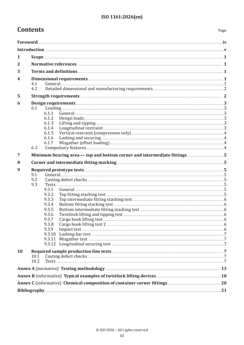
Contents Page
Foreword .iv
Introduction .v
1 Scope . 1
2 Normative references . 1
3 Terms and definitions . 1
4 Dimensional requirements . 1
4.1 General .1
4.2 Detailed dimensional and manufacturing requirements .2
5 Strength requirements . 2
6 Design requirements . 3
6.1 Loading .3
6.1.1 General .3
6.1.2 Design loads .3
6.1.3 Lifting and tipping .3
6.1.4 Longitudinal restraint .3
6.1.5 Vertical restraint (compression only) .4
6.1.6 Lashing and securing .4
6.1.7 Misgather (offset loading) .4
6.2 Compulsory features .4
7 Minimum bearing area — top and bottom corner and intermediate fittings . 5
8 Corner and intermediate fitting marking . 5
9 Required prototype tests . 5
9.1 General .5
9.2 Casting defect checks.5
9.3 Tests .5
9.3.1 General .5
9.3.2 Top fitting stacking test .5
9.3.3 Top intermediate fitting stacking test .6
9.3.4 Bottom fitting stacking test .6
9.3.5 Bottom intermediate fitting stacking test .6
9.3.6 Twistlock lifting and tipping test .6
9.3.7 Cargo hook lifting test .6
9.3.8 Cargo hook lifting test 2 .6
9.3.9 Impact test .6
9.3.10 Lashing bar test .7
9.3.11 Misgather test .7
9.3.12 Longitudinal securing test .7
10 Required sample production line tests . 7
10.1 Casting defect checks.7
10.2 Tests .7
Annex A (normative) Testing methodology .13
Annex B (informative) Typical examples of twistlock lifting devices .18
Annex C (informative) Chemical composition of container corner fittings .20
Bibliography .21
iii
Foreword
ISO (the International Organization for Standardization) is a worldwide federation of national standards
bodies (ISO member bodies). The work of preparing International Standards is normally carried out through
ISO technical committees. Each member body interested in a subject for which a technical committee
has been established has the right to be represented on that committee. International organizations,
governmental and non-governmental, in liaison with ISO, also take part in the work. ISO collaborates closely
with the International Electrotechnical Commission (IEC) on all matters of electrotechnical standardization.
The procedures used to develop this document and those intended for its further maintenance are described
in the ISO/IEC Directives, Part 1. In particular, the different approval criteria needed for the different types
of ISO document should be noted. This document was drafted in accordance with the editorial rules of the
ISO/IEC Directives, Part 2 (see www.iso.org/directives).
ISO draws attention to the possibility that the implementation of this document may involve the use of (a)
patent(s). ISO takes no position concerning the evidence, validity or applicability of any claimed patent
rights in respect thereof. As of the date of publication of this document, ISO had not received notice of (a)
patent(s) which may be required to implement this document. However, implementers are cautioned that
this may not represent the latest information, which may be obtained from the patent database available at
www.iso.org/patents. ISO shall not be held responsible for identifying any or all such patent rights.
Any trade name used in this document is information given for the convenience of users and does not
constitute an endorsement.
For an explanation of the voluntary nature of standards, the meaning of ISO specific terms and expressions
related to conformity assessment, as well as information about ISO's adherence to the World Trade
Organization (WTO) principles in the Technical Barriers to Trade (TBT), see www.iso.org/iso/foreword.html.
This document was prepared by Technical Committee ISO/TC 104, Freight containers, Subcommittee SC 1,
General purpose containers.
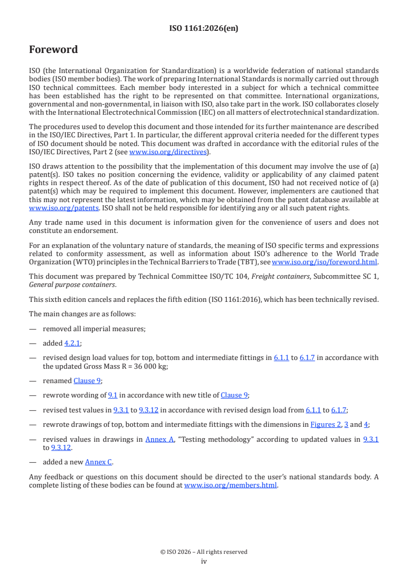
This sixth edition cancels and replaces the fifth edition (ISO 1161:2016), which has been technically revised.
The main changes are as follows:
— removed all imperial measures;
— added 4.2.1;
— revised design load values for top, bottom and intermediate fittings in 6.1.1 to 6.1.7 in accordance with
the updated Gross Mass R = 36 000 kg;
— renamed Clause 9;
— rewrote wording of 9.1 in accordance with new title of Clause 9;
— revised test values in 9.3.1 to 9.3.12 in accordance with revised design load from 6.1.1 to 6.1.7;
— rewrote drawings of top, bottom and intermediate fittings with the dimensions in Figures 2, 3 and 4;
— revised values in drawings in Annex A, “Testing methodology” according to updated values in 9.3.1
to 9.3.12.
— added a new Annex C.
Any feedback or questions on this document should be directed to the user’s national standards body. A
complete listing of these bodies can be found at www.iso.org/members.html.
iv
Introduction
This document on corner fittings represents the collaborative efforts of technical and operational experts
from all sectors of the transportation industry. Figure 1 shows the fittings for the top and bottom corners of
series 1 freight containers, which provide compatibility in interchange between transportation modes. Care
has been taken to limit consideration only to the details of fittings which are vital to this function.
This document specifies the size and configuration of corner and intermediate fitting apertures. The faces of
the corner and intermediate fittings having apertures for the engagement of handling and securing devices
have specified thickness and tolerances as shown in Figures 2 to 4. The minimum thickness of the blank
walls is specified, even though they are not involved in the engagement of the handling and securing devices;
they can be thicker than the minimum provided that their inner surfaces do not protrude into the corner
fitting cavity reserved for the engaging device.
The purpose of this document is to define some details of design vital to container interchange in automatic,
semi-automatic and conventional systems.
The strength and testing requirements specified in this document do not take any account of the stresses,
which can result from the practice of end-to-end coupling of containers.
NOTE The requirements of this document do not preclude the provision of additional facilities for lifting either
from the top or at the base of the freight container.
v
International Standard ISO 1161:2026(en)
Series 1 freight containers — Corner and intermediate fittings
— Specifications
1 Scope
This document establishes the basic dimensions and the functional and strength requirements of corner
and intermediate cast fittings for series 1 freight containers, i.e. containers which conform to ISO 668 and
ISO 1496 (all parts), with the exception of air mode containers (see ISO 8323).
Recognizing that there are containers which have ratings and dimensions different from ISO Series 1
containers referred to in ISO 668, which can be fitted with corner fitting of the same design as those
described in this document, or of another design, special arrangements for certification of any fittings for
such containers can be required.
2 Normative references
The following documents are referred to in the text in such a way that some or all of their content constitutes
requirements of this document. For dated references, only the edition cited applies. For undated references,
the latest edition of the referenced document (including any amendments) applies.
ISO 1496-1, Series 1 freight containers — Specification and testing — Part 1: General cargo containers for
general purposes
ISO 148-1, Metallic materials — Charpy pendulum impact test — Part 1: Test method
ISO 3874, Series 1 freight containers — Handling and securing
3 Terms and definitions
No terms and definitions are listed in this document.
ISO and IEC maintain terminology databases for use in standardization at the following addresses:
— ISO Online browsing platform: available at https:// www .iso .org/ obp
— IEC Electropedia: available at https:// www .electropedia .org/
4 Dimensional requirements
4.1 General
The dimensions and tolerances of the corner fittings shall conform to Figures 2, 3 and 4. A general view of
container fittings is shown in Figure 1.
Each series 1 container shall have two right-hand top corner fittings (on the right as the observer faces
either end of the container) and two left-hand top corner fittings, which are the mirror image of the right-
hand fittings.
The bottom corner fittings shall have a similar configuration except in respect of the end (i.e. front or rear
faces aperture.
45 ft containers shall have intermediate fitting in the 40 ft position (see Figure 1). The dimensions and
tolerances of the intermediate fittings shall conform to Figure 3 and Figure 4.
Figure 2 illustrates the left-hand top corner fitting and the right-hand top corner fitting as symmetrical.
Figure 3 illustrates the left-hand top intermediate fitting and the right-hand intermediate fitting as
symmetrical.
Figure 4 illustrates the left-hand bottom corner fitting, the intermediate fitting, the right-hand bottom
corner fitting and the intermediate fitting as symmetrical.
4.2 Detailed dimensional and manufacturing requirements
4.2.1 Sharp corners shall be removed as far as practicable (see Figure A.1).
4.2.2 Where the dimensions are not specified for inner and outer edges of apertures, these edges shall be
given a radius of: 3 (0 −1,5) mm,
4.2.3 At the junction of the two 6 mm outside edge radii with the 14,5 mm edge radius, the corner should
be rounded by blending the radiused edges, removing minimum amounts of material from the flat outer
faces and walls. Generally, it shall be spherical and the maximum radius shall be no more than 30 mm.
5 Strength requirements
The corner or intermediate fittings shall be designed, constructed and tested in such a manner and of such
materials as to enable them to pass the operating and testing requirements of ISO 1496-1 in addition to the
requirements in Clause 9 and Clause 10.
The mechanical properties of raw materials used shall result in producing corner fittings that meet or
exceed the following:
Yield strength: 275 MPa
Tensile strength: 480 MPa
a
Impact energy at – 20 °C 27 J
a
Impact energy at - 40 °C 21 J
Elongation: 25 %
Reduction of area: 40 %
a
Impact tests shall be in accordance with ISO 148-1.
The above are the minimum values for strength requirements. Certification societies may approve higher
values, but shall not approve lower values. Testing at temperatures lower than −40 °C may be approved, if
required.
Manufacturers are responsible for ensuring that quantities of undesirable eleme
...