

IEC 60034-14:2026
(Main)Rotating electrical machines - Part 14: Mechanical vibration of certain machines with shaft heights 56 mm and higher - Measurement, evaluation and limits of vibration severity
- Abstract
IEC 60034-14:2026 specifies the factory acceptance vibration test procedures and vibration limits for certain electrical machines under specified conditions, when uncoupled from any load or prime mover. It is applicable to DC and three-phase AC machines, with shaft heights 56 mm and higher and a rated output up to 50 MW, at operational speeds from 120 min–1 up to and including 15 000 min–1. This document is not applicable to machines mounted in situ (on site), three-phase commutator motors, single-phase machines, three-phase machines operated on single-phase systems, vertical waterpower generators, turbine generators greater than 20 MW and machines with magnetic bearings or series-wound machines.
NOTE 1 For machines measured in situ, refer to applicable clauses or subclauses of ISO 20816‑1 and ISO 20816‑3.
NOTE 2 For output power above 50 MW reference is made to the ISO 20816 series.
NOTE 3 Vibration routine tests are not mandatory according to IEC 60034‑1. If performed, the method for testing is included in this document.
This fifth edition cancels and replaces the fourth edition published in 2018. This edition constitutes a technical revision. This edition includes the following significant technical changes with respect to the previous edition:
a) subclause 6.3.3 Vertical machines: added two new subclauses: Type and routine tests;
b) subclause 7.3 Test conditions: added two new subclauses: Direct-on-line and variable speed;
c) Table 1: decreased limits for Grade A in free suspension for 56 ≤ H ≤ 132 mm;
d) Clause 9 Limits of relative shaft vibration: added information how to mitigate effects of run-out on shaft vibration measurements.
- Status
- Published
- Publication Date
- 09-Nov-2026
- Technical Committee
- TC 2 - Rotating machinery
- Drafting Committee
- MT 2 - TC 2/MT 2
- Current Stage
- PPUB - Publication issued
- Start Date
- 10-Nov-2026
- Completion Date
- 27-Nov-2026
Buy Documents
REDLINE IEC 60034-14:2026 CMV - Rotating electrical machines - Part 14: Mechanical vibration of certain machines with shaft heights 56 mm and higher - Measurement, evaluation and limits of vibration severity
iec60034-14{ed5.0}en - Rotating electrical machines - Part 14: Mechanical vibration of certain machines with shaft heights 56 mm and higher - Measurement, evaluation and limits of vibration severity
iec60034-14{ed5.0}fr - Machines électriques tournantes - Partie 14: Vibrations mécaniques de certaines machines de hauteur d'axe supérieure ou égale à 56 mm - Mesurage, évaluation et limites de l'intensité vibratoire
IEC 60034-14:2026 is an IEC International Standard for factory acceptance vibration testing of certain rotating electrical machines. It specifies how to measure, evaluate and limit vibration severity for DC and three-phase AC machines with shaft heights 56 mm and higher, when the machine is uncoupled from any load or prime mover. The document gives a common factory method for manufacturers, test laboratories, suppliers and purchasers who need comparable vibration results.
What does IEC 60034-14:2026 specify?
IEC 60034-14:2026 specifies factory acceptance vibration test procedures and vibration limits for certain electrical machines under defined conditions. It applies to machines up to 50 MW and operational speeds from 120 min-1 up to and including 15 000 min-1.
The scope excludes in situ machines, three-phase commutator motors, single-phase machines, three-phase machines operated on single-phase systems, vertical waterpower generators, turbine generators greater than 20 MW, machines with magnetic bearings and series-wound machines. For the overall document structure, Clause 1 sets the scope, Clauses 2 to 7 cover references, terms, measurement quantities, equipment, mounting and measurement conditions, and Clauses 8 and 9 give the vibration limits for bearing housings and relative shaft vibration.
What are the key requirements of IEC 60034-14:2026?
IEC 60034-14:2026 focuses on how to measure vibration in a repeatable way, how to mount the machine during the test, and how to judge the result against the limits in Table 1 and Table 2. In practice, the standard is about getting a factory test setup that reflects the machine itself, not accidental vibration from the support, sensors or test floor.
Measurement quantities and equipment
Clause 4 uses two main measurement quantities at the bearings: vibration displacement and vibration velocity. It also uses relative shaft vibration displacement within or near the machine bearings. That means the test record has to show the right physical quantity for the machine and speed range, not just a general vibration reading.
Clause 5 requires measurement equipment with a broadband root mean square (RMS) response over 10 Hz to 1 000 Hz, with the lower limit not greater than 2 Hz for machines running at or below 600 min-1. This matters because the instrument bandwidth can change the result, especially on slow machines. Relative shaft vibration equipment has to comply with ISO 10817-1, and multi-directional sensors shall not be used.
Machine mounting
Clause 6 makes the mounting condition part of the test method. Free suspension means the machine is hung or mounted on an elastic support, while rigid mounting means a massive foundation or a sufficiently rigid test floor stand with no elastic mounts. This matters because the same machine can give different readings depending on how it is supported.
For free suspension, the machine and support system must have a sufficiently low natural frequency relative to the machine speed, and the arrangement is only practical for certain speed ranges. For rigid mounting, the test arrangement shall avoid resonance near rotational frequency, twice rotational frequency, and once or twice the fundamental electrical supply frequency. Horizontal machines are to be bolted or clamped using all bolt-hole positions, and vertical machines have specific support plate requirements in 6.3.3.
Clause 6.3.3 separates vertical machines into type test and routine test arrangements. That is important in practice because the document recognizes that a vertical machine may need a dedicated test support for type testing, while a routine test may use another arrangement when the design has already been characterized.
Clause 6.4 introduces active environment. If the standstill vibration at the same position is more than 25% of the running value, the environment is active and the document does not apply. In practice, this prevents a test setup from being accepted when external disturbance is dominating the result.
Measurement positions and test conditions
Clause 7 fixes where and how to measure. The preferred bearing vibration positions are shown in Figures 2, 3, 4 and 6, depending on end-shield bearings, pedestal bearings or vertical machines. For relative shaft displacement, non-contacting transducers are installed inside the bearing or adjacent to the bearing shell, with preferred radial positions shown in Figure 5.
Clause 7.1 also requires the shaft extension keyway key to be treated according to ISO 21940-32, unless the customer specifies otherwise. That matters because the key condition can change balancing and vibration behavior.
Clause 7.3 defines two main test conditions: direct-on-line and variable speed. Direct-on-line testing is at no-load with rated frequency and voltage, and multi-speed machines are tested for each pole number. Variable-speed machines are tested over the specified speed range with a ramp or coast down slow enough to capture peak levels. For routine testing of variable-speed machines, a single speed may be used when type-test information supports it.
Clause 7.4 requires the transducer mounting to follow the transducer manufacturer’s instructions and not disturb the machine. The total coupled mass of the transducer assembly must be small enough not to affect the vibration behavior. That is a practical reminder that the sensor installation is part of the test quality.
Limits and grades
Clause 8 gives the acceptance limits for bearing housing vibration. The standard uses two grades: Grade A for machines with no special vibration requirements, and Grade B for machines with special vibration requirements. When no grade is specified, the machine is expected to meet Grade A.
The limits depend on shaft height, mounting condition and whether the result is expressed as displacement or velocity. For routine tests, displacement is used below 600 min-1 and velocity from 600 min-1 to 15 000 min-1. Vibration above 1 000 Hz should be filtered out. If a free suspension routine test is used, the type test should also include rigid mounting.
Clause 8.2 addresses AC machines with a dominant twice-line frequency component. For certain machines with shaft heights above 132 mm, the limit is handled differently when that electrical component dominates. In practice, this clause prevents a machine from being judged only by a mechanical vibration limit when electromagnetic excitation is the main source.
Clause 8.3 covers axial vibration. For thrust bearings, axial vibration is evaluated in the same way as transverse vibration and the same limits apply. For bearings without axial limiting construction, a different arrangement may be agreed between supplier and customer.
Relative shaft vibration
Clause 9 is mainly for sleeve-bearing machines. Relative shaft vibration measurements are recommended only for machines with speeds above 1 200 min-1 and rated power above 1 000 kW, and the transducer installation has to be agreed in advance. The limits in Table 2 include run-out, so the measured value is not just shaft motion from vibration alone.
Clause 9 also explains how electrical run-out can mask true shaft vibration. In practice, that may require slow-roll compensation, a sleeve to improve shaft surface uniformity, or fixing the rotor to reduce axial movement during measurement.
What terms does IEC 60034-14:2026 define?
- Vibration magnitude - The broadband RMS vibration displacement or vibration velocity measured at the machine bearings and used to judge the machine against the limit tables.
- Relative shaft vibration - The vibratory peak-to-peak displacement measured directly on the shaft journal direction, usually with non-contacting transducers.
- Free suspension - A mounting condition where the machine is supported on springs or other elastic supports so that its own vibration can be measured with limited influence from the support.
- Rigid mounting - A mounting condition using a massive foundation or rigid test floor stand, without elastic mounts, to minimize support influence on the measurement.
- Active environment - A test environment in which the standstill vibration at the same measurement position is more than 25% of the running vibration, so the document does not apply.
- Run-out - The combined mechanical and electrical variation seen during shaft vibration measurement, which is included in the relative shaft vibration limits.
- Grade A - The default vibration grade for machines with no special vibration requirements.
- Grade B - The vibration grade for machines with special vibration requirements.
Who uses IEC 60034-14:2026?
IEC 60034-14:2026 is used by manufacturers of rotating electrical machines, factory test laboratories, quality and acceptance engineers, and purchasers who specify acceptance criteria. It is especially relevant for DC machines and three-phase AC motors and generators that are tested before shipment.
It is also used when supplier and customer need to agree on mounting, measurement positions, special test arrangements for vertical machines, or special cases such as sleeve-bearing machines with shaft vibration measurements. In practice, it supports procurement, factory acceptance, and test documentation for rotating machinery.
What changed in IEC 60034-14:2026 from the previous edition?
IEC 60034-14:2026 cancels and replaces the fourth edition published in 2018. It is identified as a technical revision.
The significant changes stated for this edition are:
- Clause 6.3.3 for vertical machines adds separate subclauses for type tests and routine tests.
- Clause 7.3 adds direct-on-line and variable speed test conditions.
- Table 1 reduces the Grade A limits in free suspension for shaft heights 56 ≤ H ≤ 132 mm.
- Clause 9 adds guidance on mitigating the effects of run-out in shaft vibration measurements.
Which standards are used with IEC 60034-14:2026?
IEC 60034-14:2026 uses several referenced standards to define instruments, mounting practice and related vibration terms:
- IEC 60034-1 - provides rating and performance requirements and supplies the base terms and definitions used in this part.
- IEC 60034-7 - classifies machine construction and mounting arrangements, including the IM Code used for vertical machine examples.
- ISO 2954 - sets requirements for instruments used to measure vibration severity.
- ISO 10817-1 - covers rotating shaft vibration measuring systems for relative and absolute sensing.
- ISO 20816-1 - gives general guidelines for machine vibration measurement and evaluation, including the concept of active environment.
- ISO 21940-32 - gives the shaft and fitment key convention used for balancing-related treatment of keyways.
For in situ vibration assessment, the scope points to ISO 20816-1 and ISO 20816-3, and for outputs above 50 MW it points to the ISO 20816 series.
What does the IEC 60034-14:2026 document contain?
The document contains the full test method framework for factory vibration acceptance of certain rotating electrical machines. It includes the measurement quantities, required instrument behavior, mounting arrangements for free suspension, rigid mounting and vertical machines, and the rules for identifying an active environment.
It also includes figures showing minimum elastic displacement, preferred measurement positions, alternative positions where disassembly would otherwise be needed, pedestal bearing positions, transducer positions for shaft displacement, vertical machine setups and the vibration limit diagram for higher shaft heights. Table 1 gives the bearing-housing vibration limits by grade, shaft height and mounting condition, and Table 2 gives the relative shaft displacement and run-out limits for sleeve-bearing machines.
Relations
- Effective Date
- 26-Oct-2025
Buy Documents
REDLINE IEC 60034-14:2026 CMV - Rotating electrical machines - Part 14: Mechanical vibration of certain machines with shaft heights 56 mm and higher - Measurement, evaluation and limits of vibration severity
iec60034-14{ed5.0}en - Rotating electrical machines - Part 14: Mechanical vibration of certain machines with shaft heights 56 mm and higher - Measurement, evaluation and limits of vibration severity
iec60034-14{ed5.0}fr - Machines électriques tournantes - Partie 14: Vibrations mécaniques de certaines machines de hauteur d'axe supérieure ou égale à 56 mm - Mesurage, évaluation et limites de l'intensité vibratoire
Get Certified
Connect with accredited certification bodies for this standard

IMQ S.p.A. (Certification)
Italian electrical product certification.

SLG Prüf- und Zertifizierungs GmbH
German testing and certification body.

UL Solutions
Global safety science company with testing, inspection and certification.
Sponsored listings
Frequently Asked Questions
IEC 60034-14:2026 is a standard published by the International Electrotechnical Commission (IEC). Its full title is "Rotating electrical machines - Part 14: Mechanical vibration of certain machines with shaft heights 56 mm and higher - Measurement, evaluation and limits of vibration severity". This standard covers: IEC 60034-14:2026 specifies the factory acceptance vibration test procedures and vibration limits for certain electrical machines under specified conditions, when uncoupled from any load or prime mover. It is applicable to DC and three-phase AC machines, with shaft heights 56 mm and higher and a rated output up to 50 MW, at operational speeds from 120 min–1 up to and including 15 000 min–1. This document is not applicable to machines mounted in situ (on site), three-phase commutator motors, single-phase machines, three-phase machines operated on single-phase systems, vertical waterpower generators, turbine generators greater than 20 MW and machines with magnetic bearings or series-wound machines. NOTE 1 For machines measured in situ, refer to applicable clauses or subclauses of ISO 20816‑1 and ISO 20816‑3. NOTE 2 For output power above 50 MW reference is made to the ISO 20816 series. NOTE 3 Vibration routine tests are not mandatory according to IEC 60034‑1. If performed, the method for testing is included in this document. This fifth edition cancels and replaces the fourth edition published in 2018. This edition constitutes a technical revision. This edition includes the following significant technical changes with respect to the previous edition: a) subclause 6.3.3 Vertical machines: added two new subclauses: Type and routine tests; b) subclause 7.3 Test conditions: added two new subclauses: Direct-on-line and variable speed; c) Table 1: decreased limits for Grade A in free suspension for 56 ≤ H ≤ 132 mm; d) Clause 9 Limits of relative shaft vibration: added information how to mitigate effects of run-out on shaft vibration measurements.
IEC 60034-14:2026 specifies the factory acceptance vibration test procedures and vibration limits for certain electrical machines under specified conditions, when uncoupled from any load or prime mover. It is applicable to DC and three-phase AC machines, with shaft heights 56 mm and higher and a rated output up to 50 MW, at operational speeds from 120 min–1 up to and including 15 000 min–1. This document is not applicable to machines mounted in situ (on site), three-phase commutator motors, single-phase machines, three-phase machines operated on single-phase systems, vertical waterpower generators, turbine generators greater than 20 MW and machines with magnetic bearings or series-wound machines. NOTE 1 For machines measured in situ, refer to applicable clauses or subclauses of ISO 20816‑1 and ISO 20816‑3. NOTE 2 For output power above 50 MW reference is made to the ISO 20816 series. NOTE 3 Vibration routine tests are not mandatory according to IEC 60034‑1. If performed, the method for testing is included in this document. This fifth edition cancels and replaces the fourth edition published in 2018. This edition constitutes a technical revision. This edition includes the following significant technical changes with respect to the previous edition: a) subclause 6.3.3 Vertical machines: added two new subclauses: Type and routine tests; b) subclause 7.3 Test conditions: added two new subclauses: Direct-on-line and variable speed; c) Table 1: decreased limits for Grade A in free suspension for 56 ≤ H ≤ 132 mm; d) Clause 9 Limits of relative shaft vibration: added information how to mitigate effects of run-out on shaft vibration measurements.
IEC 60034-14:2026 is classified under the following ICS (International Classification for Standards) categories: 29.160.01 - Rotating machinery in general. The ICS classification helps identify the subject area and facilitates finding related standards.
IEC 60034-14:2026 has the following relationships with other standards: It is inter standard links to IEC 60034-14:2018. Understanding these relationships helps ensure you are using the most current and applicable version of the standard.
IEC 60034-14:2026 is available in PDF format for immediate download after purchase. The document can be added to your cart and obtained through the secure checkout process. Digital delivery ensures instant access to the complete standard document.
Standards Content (Sample)
IEC 60034-14 ®
Edition 5.0 2026-11
INTERNATIONAL
STANDARD
COMMENTED VERSION
Rotating electrical machines -
Part 14: Mechanical vibration of certain machines with shaft heights 56 mm and
higher - Measurement, evaluation and limits of vibration severity
ICS 29.160.01 ISBN 978-2-8327-1618-2
All rights reserved. Unless otherwise specified, no part of this publication may be reproduced or utilized in any form or
by any means, electronic or mechanical, including photocopying and microfilm, without permission in writing from either
IEC or IEC's member National Committee in the country of the requester. If you have any questions about IEC copyright
or have an enquiry about obtaining additional rights to this publication, please contact the address below or your local
IEC member National Committee for further information.
IEC Secretariat Tel.: +41 22 919 02 11
3, rue de Varembé info@iec.ch
CH-1211 Geneva 20 www.iec.ch
Switzerland
About the IEC
The International Electrotechnical Commission (IEC) is the leading global organization that prepares and publishes
International Standards for all electrical, electronic and related technologies.
About IEC publications
The technical content of IEC publications is kept under constant review by the IEC. Please make sure that you have the
latest edition, a corrigendum or an amendment might have been published.
IEC publications search - IEC Products & Services Portal - products.iec.ch
webstore.iec.ch/advsearchform Discover our powerful search engine and read freely all the
The advanced search enables to find IEC publications by a publications previews, graphical symbols and the glossary.
variety of criteria (reference number, text, technical With a subscription you will always have access to up to date
committee, …). It also gives information on projects, content tailored to your needs.
replaced and withdrawn publications.
Electropedia - www.electropedia.org
The world's leading online dictionary on electrotechnology,
IEC Just Published - webstore.iec.ch/justpublished
Stay up to date on all new IEC publications. Just Published containing more than 22 500 terminological entries in English
details all new publications released. Available online and and French, with equivalent terms in 25 additional languages.
once a month by email. Also known as the International Electrotechnical Vocabulary
(IEV) online.
IEC Customer Service Centre - webstore.iec.ch/csc
If you wish to give us your feedback on this publication or
need further assistance, please contact the Customer
Service Centre: sales@iec.ch.
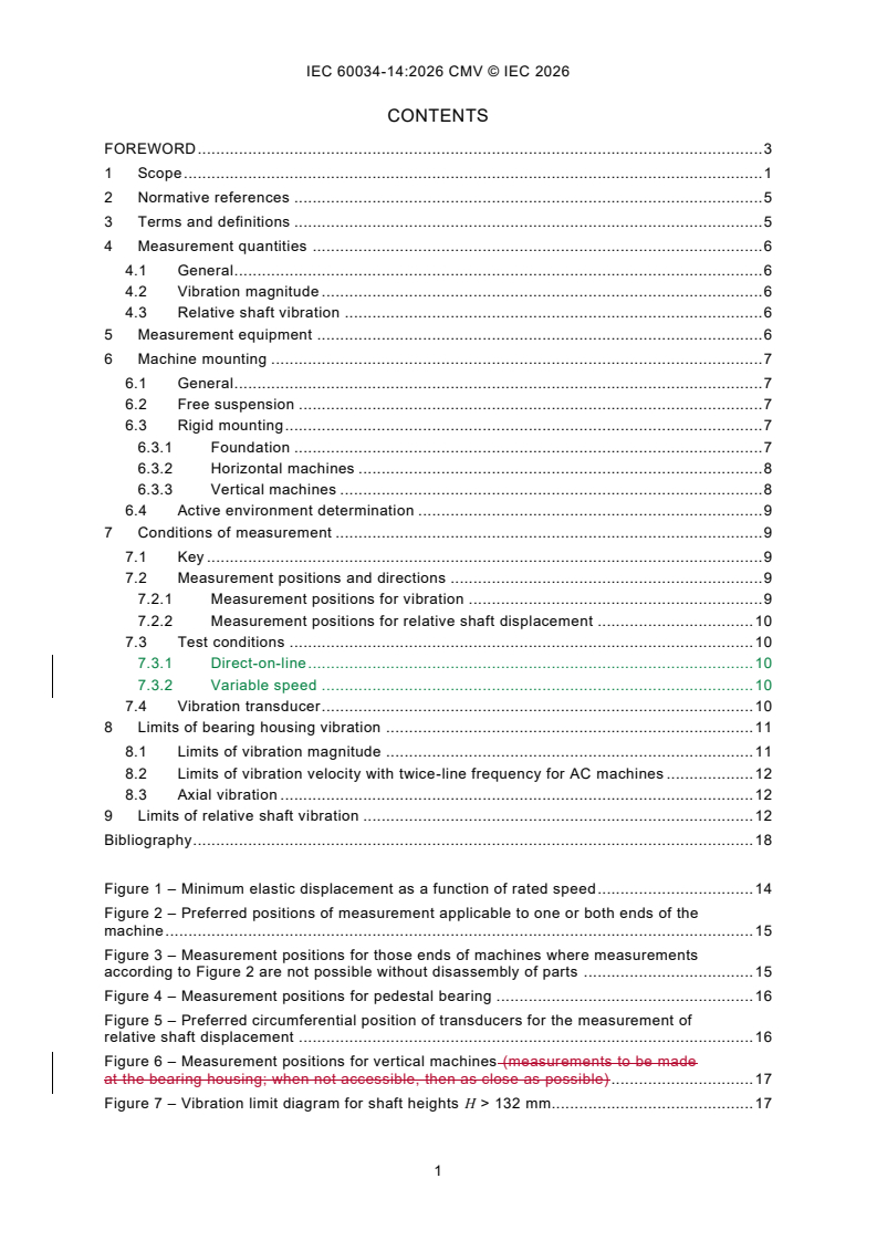
CONTENTS
FOREWORD . 3
1 Scope . 1
2 Normative references . 5
3 Terms and definitions . 5
4 Measurement quantities . 6
4.1 General . 6
4.2 Vibration magnitude . 6
4.3 Relative shaft vibration . 6
5 Measurement equipment . 6
6 Machine mounting . 7
6.1 General . 7
6.2 Free suspension . 7
6.3 Rigid mounting . 7
6.3.1 Foundation . 7
6.3.2 Horizontal machines . 8
6.3.3 Vertical machines . 8
6.4 Active environment determination . 9
7 Conditions of measurement . 9
7.1 Key . 9
7.2 Measurement positions and directions . 9
7.2.1 Measurement positions for vibration . 9
7.2.2 Measurement positions for relative shaft displacement . 10
7.3 Test conditions . 10
7.3.1 Direct-on-line . 10
7.3.2 Variable speed . 10
7.4 Vibration transducer . 10
8 Limits of bearing housing vibration . 11
8.1 Limits of vibration magnitude . 11
8.2 Limits of vibration velocity with twice-line frequency for AC machines . 12
8.3 Axial vibration . 12
9 Limits of relative shaft vibration . 12
Bibliography . 18
Figure 1 – Minimum elastic displacement as a function of rated speed. 14
Figure 2 – Preferred positions of measurement applicable to one or both ends of the
machine . 15
Figure 3 – Measurement positions for those ends of machines where measurements
according to Figure 2 are not possible without disassembly of parts . 15
Figure 4 – Measurement positions for pedestal bearing . 16
Figure 5 – Preferred circumferential position of transducers for the measurement of
relative shaft displacement . 16
Figure 6 – Measurement positions for vertical machines (measurements to be made
at the bearing housing; when not accessible, then as close as possible) . 17
Figure 7 – Vibration limit diagram for shaft heights H > 132 mm. 17
Table 1 – Limits of maximum vibration magnitude in displacement (RMS) and
velocity (RMS) for shaft height H . 11
Table 2 – Limits for the maximum shaft vibration (S ) and the maximum run-out . 13
p-p
INTERNATIONAL ELECTROTECHNICAL COMMISSION
____________
Rotating electrical machines -
Part 14: Mechanical vibration of certain machines
with shaft heights 56 mm and higher -
Measurement, evaluation and limits of vibration severity
FOREWORD
1) The International Electrotechnical Commission (IEC) is a worldwide organization for standardization comprising
all national electrotechnical committees (IEC National Committees). The object of IEC is to promote international
co-operation on all questions concerning standardization in the electrical and electronic fields. To this end and
in addition to other activities, IEC publishes International Standards, Technical Specifications, Technical Reports,
Publicly Available Specifications (PAS) and Guides (hereafter referred to as "IEC Publication(s)"). Their
preparation is entrusted to technical committees; any IEC National Committee interested in the subject dealt with
may participate in this preparatory work. International, governmental and non-governmental organizations liaising
with the IEC also participate in this preparation. IEC collaborates closely with the International Organization for
Standardization (ISO) in accordance with conditions determined by agreement between the two organizations.
2) The formal decisions or agreements of IEC on technical matters express, as nearly as possible, an international
consensus of opinion on the relevant subjects since each technical committee has representation from all
interested IEC National Committees.
3) IEC Publications have the form of recommendations for international use and are accepted by IEC National
Committees in that sense. While all reasonable efforts are made to ensure that the technical content of IEC
Publications is accurate, IEC cannot be held responsible for the way in which they are used or for any
misinterpretation by any end user.
4) In order to promote international uniformity, IEC National Committees undertake to apply IEC Publications
transparently to the maximum extent possible in their national and regional publications. Any divergence between
any IEC Publication and the corresponding national or regional publication shall be clearly indicated in the latter.
5) IEC itself does not provide any attestation of conformity. Independent certification bodies provide conformity
assessment services and, in some areas, access to IEC marks of conformity. IEC is not responsible for any
services carried out by independent certification bodies.
6) All users should ensure that they have the latest edition of this publication.
7) No liability shall attach to IEC or its directors, employees, servants or agents including individual experts and
members of its technical committees and IEC National Committees for any personal injury, property damage or
other damage of any nature whatsoever, whether direct or indirect, or for costs (including legal fees) and
expenses arising out of the publication, use of, or reliance upon, this IEC Publication or any other IEC
Publications.
8) Attention is drawn to the Normative references cited in this publication. Use of the referenced publications is
indispensable for the correct application of this publication.
9) IEC draws attention to the possibility that the implementation of this document may involve the use of (a)
patent(s). IEC takes no position concerning the evidence, validity or applicability of any claimed patent rights in
respect thereof. As of the date of publication of this document, IEC had not received notice of (a) patent(s), which
may be required to implement this document. However, implementers are cautioned that this may not represent
the latest information, which may be obtained from the patent database available at https://patents.iec.ch. IEC
shall not be held responsible for identifying any or all such patent rights.
This commented version (CMV) of the official standard IEC 60034-14:2026 edition 5.0 allows
the user to identify the changes made to the previous IEC 60034-14:2018 edition 4.0.
Furthermore, comments from IEC TC 2 experts are provided to explain the reasons of the most
relevant changes, or to clarify any part of the content.
A vertical bar appears in the margin wherever a change has been made. Additions are shown
in green text, and deletions in red text with strikethrough. Hover over the comment icons to
display pop-up notes containing the comments, which are also available in the margin of the
publication.
This publication contains the CMV and the official standard.
IEC 60034-14 has been prepared by IEC technical committee 2: Rotating machinery. It is an
International Standard.
This fifth edition cancels and replaces the fourth edition published in 2018. This edition
constitutes a technical revision.
This edition includes the following significant technical changes with respect to the previous
edition:
a) subclause 6.3.3 Vertical machines: added two new subclauses: Type and routine tests;
b) subclause 7.3 Test conditions: added two new subclauses: Direct-on-line and variable
speed;
c) Table 1: decreased limits for Grade A in free suspension for 56 ≤ H ≤ 132 mm;
d) Clause 9 Limits of relative shaft vibration: added information how to mitigate effects of run -
out on shaft vibration measurements.
The text of this International Standard is based on the following documents:
Draft Report on voting
2/2323/FDIS 2/2329/RVD
Full information on the voting for its approval can be found in the report on voting indicated in
the above table.
The language used for the development of this International Standard is English.
This document was drafted in accordance with ISO/IEC Directives, Part 2, and developed in
accordance with ISO/IEC Directives, Part 1 and ISO/IEC Directives, IEC Supplement, available
at www.iec.ch/members_experts/refdocs. The main document types developed by IEC are
described in greater detail at www.iec.ch/publications.
A list of all parts in the IEC 60034 series, published under the general title Rotating electrical
machines, can be found on the IEC website.
NOTE A table of cross-references of all IEC TC 2 publications can be found in the IEC TC 2 dashboard on the IEC
website.
The committee has decided that the contents of this document will remain unchanged until the
stability date indicated on the IEC website under webstore.iec.ch in the data related to the
specific document. At this date, the document will be
– reconfirmed,
– withdrawn, or
– revised.
1 Scope
This part of IEC 60034 specifies the factory acceptance vibration test procedures and vibration
limits for certain electrical machines under specified conditions, when uncoupled from any load
or prime mover.
It is applicable to DC and three-phase AC machines, with shaft heights 56 mm and higher and
–1
a rated output up to 50 MW, at operational speeds from 120 min up to and including
–1
15 000 min .
This document is not applicable to machines mounted in situ (on site), three-phase commutator
motors, single-phase machines, three-phase machines operated on single-phase systems,
vertical waterpower generators, turbine generators greater than 20 MW and machines with
magnetic bearings or series-wound machines.
NOTE 1 For machines measured in situ, refer to applicable clauses or subclauses of ISO 20816, ISO 10816 and
ISO 7919 ISO 20816-1 and ISO 20816-3.
NOTE 2 For output power above 50 MW reference is made to the ISO 20816 series.
NOTE 3 Vibration routine tests are not mandatory according to IEC 60034-1. If performed, the method for testing
is included in this document.
2 Normative references
The following documents are referred to in the text in such a way that some or all their content
constitutes requirements of this document. For dated references, only the edition cited applies.
For undated references, the latest edition of the referenced document (including any
amendments) applies.
IEC 60034-1, Rotating electrical machines - Part 1: Rating and performance
IEC 60034-7, Rotating electrical machines – Part 7: Classification of types of constructions and
mounting arrangements (IM Code)
ISO 2954, Mechanical vibration of rotating and reciprocating machinery - Requirements for
instruments for measuring vibration severity
ISO 10817-1, Rotating shaft vibration measuring systems - Part 1: Relative and absolute
sensing of radial vibration from rotating shafts
ISO 20816-1, Mechanical vibration - Measurement and evaluation of machine vibration - Part 1:
General guidelines
ISO 21940-32, Mechanical vibration - Rotor balancing - Part 32: Shaft and fitment key
convention
3 Terms and definitions
For the purposes of this document, the terms and definitions given in IEC 60034-1 apply.
ISO and IEC maintain terminology databases for use in standardization at the following
addresses:
– IEC Electropedia: available at https://www.electropedia.org/
– ISO Online browsing platform: available at https://www.iso.org/obp
4 Measurement quantities
4.1 General
Measurement quantities are the vibration displacement and vibration velocity at the machine
bearings and the relative shaft vibration displacement within or near the machine bearings.
4.2 Vibration magnitude
The criterion for the vibration magnitude measured at the machine bearings shall be the
broadband RMS value of the vibration displacement in micrometers or the vibration velocity in
millimeters per second in the frequency range specified in Clause 5. The maximum value,
determined at the specified measurement positions and specified measuring variable, according
to this document, characterizes the vibration magnitude of the machine.
Induction motors (especially of two-pole type) frequently show vibration beating at twice slip
frequency. In these cases, the decisive vibration magnitude shall be determined from the
relationship:
xx+
max min
x =
RMS
where
x is the maximum RMS value of vibration displacement or vibration velocity;
max
x is the minimum RMS value of vibration displacement or vibration velocity.
min
The chosen sample rate shall be large enough to reliably capture the maximum and minimum
values of the vibration.
NOTE Large AC induction machines running at very low slip values at no load may can require several minutes to
more than ten minutes for such measurements to be completed at each vibration measuring position.
4.3 Relative shaft vibration
The criterion adopted for the relative shaft vibration measurement shall be the vibratory peak-
to-peak displacement (S ) in the direction of measurement from ISO 20816-1.
p-p
5 Measurement equipment
The measurement equipment shall be capable of measuring broadband RMS vibration with flat
response over a frequency range of 10 Hz to 1 000 Hz, in accordance with the requirements of
–1
ISO 2954. However, for machines with speeds approaching or below 600 min , the lower limit
of the flat response frequency range shall not be greater than 2 Hz.
Measurement equipment for relative shaft vibration measurements shall comply with the
requirements in ISO 10817-1.
Multi-directional vibration sensors shall not be used.
NOTE Multi-directional sensors do not provide proper vibration measurement in all directions when mounted in only
one location.
6 Machine mounting
6.1 General
The vibration of an electrical machine is closely linked with the mounting of the machine. To
permit evaluation as far as balance and vibration of rotating electrical machines are
concerned, it is necessary to measure the vibration on the machine alone, under properly
determined test conditions, to enable reproducible tests to be carried out and to provide
comparable measurements.
6.2 Free suspension
This condition is achieved by suspending the machine on a spring or by mounting on an elastic
support (springs, rubber, etc.).
The h i g h e s t natural oscillation frequency (f ) of the suspension system and machine shall
no
be less than 1/3 of the frequency f corresponding to the speed of the machine under test, as
defined in 7.3. Based on the mass of the machine being tested, the necessary elasticity of the
–1 –1
suspension system as a function of rated speed from 600 min to 3 600 min can be
–1
determined from Figure 1. For speeds lower than 600 min measurements in free suspension
–1
are not practical. For speeds greater than 3 600 min , the static displacement Z should be not
–1
less than the value for 3 600 min .
The curve in Figure 1 presents the minimum elastic displacement to attain the necessary
vertical rigid body natural oscillation, which is usually the highest rigid body natural frequency.
Static displacement Z is expressed as:
ag f
Z = ,a = ; a 3
f
2πn no
( )
where
Z is the displacement in m,
–1
n is the rated speed in units of s , and
g is the acceleration of gravity (9,81 m/s ).
When a is set to 3, then the curve in Figure 1 is generated.
The suspension system should exhibit linear stiffness characteristics within the operating
displacement range.
6.3 Rigid mounting
6.3.1 Foundation
6.3.1.1 General
During the shop running factory acceptance test of the assembled machine, vibration
measurements shall be made with the machine properly mounted, shimmed if necessary, and
securely fastened to a massive foundation or test floor stand. Elastic mounts are not permitted.
NOTE 1 For proper mounting, shimming can be applied: Typically shimmed to within 25 µm to 50 µm (approximately
1 mil to 2 mil) to avoid soft foot.
The horizontal and vertical natural frequencies of the complete test arrangement shall not
coincide within:
a) ±10 % of the rotational frequency of the machine;
b) ±5 % of twice the rotational frequency; or
c) ±5 % of once and twice the fundamental electrical line supply frequency.
NOTE 2 These criteria apply to each rated speed according to 7.3.1.
Either one of the following two mounting conditions may be chosen by the manufacturer.
6.3.1.2 Rigid mounting on massive foundation
One indication of massive foundation is when the vibration velocity measured in the horizontal
and vertical directions at the machine feet (or at the base frame near to the bearing pedestals
or stator feet) does not exceed 30 % of the maximum velocity, which is measured at the adjacent
bearing housing in the same measurement direction. The ratio of foot to bearing vibration
velocities is valid for the rotational frequency component or twice-line frequency component (if
the latter is being evaluated).
NOTE 1 The rigidity of a foundation is a relative quantity. It is compared with the rigidity of the machine bearing
system. The ratio of bearing housing vibration to foundation vibration is a characteristic quantity for the evalu ation
of foundation flexibility.
NOTE 2 If the machine is to be supported in the field by a structure other than a massive foundation, it may be
necessary to perform a system dynamic analysis to make the necessary changes to the foundation dynamic stiffness.
If the machine will be installed in the field (in situ) on a structure that is not a massive foundation, a system dynamic
analysis can be required to assess and adjust the dynamic stiffness of the field supporting structure.
6.3.1.3 Rigid mounting on test floor stand
This condition is achieved by mounting the machine on an adequately rigid test foundation free
of resonances at forcing frequencies, see 6.3.1.1.
NOTE This mounting is the most used in manufacturers test labs.
6.3.2 Horizontal machines
The machine under test shall be bolted or clamped using all bolt-hole positions to a foundation
that meets the requirements of 6.3.1.2 or 6.3.1.3.
There are constructions and mountings in which the above fixing conditions cannot be met.
Examples include single-bearing or flange mounted machines. In those cases, there should be
an agreement between the supplier and customer.
6.3.3 Vertical machines
Vertical machines shall be mounted onto a solid rectangular or circular steel plate with a bore
hole in the centre of the shaft extension, a machined surface for the flange of electrical machine
being measured and holes provided for fasteners or clamps. The steel plate thickness shall be
at least three times greater than the machine flange thickness, five times is recommended. The
edge length respective to the diameter shall be at least equal to the height of the top bearing,
L. Figure 6 is an example for IM V1 (see IEC 60034-7).
6.3.3.1 Type test
Vertical electrical machines shall be mounted on a solid steel plate, either rectangular or
circular, with the following features:
– a central bore hole aligned with the shaft extension;
– a machined surface to support the machine flange accurately;
– holes for fasteners or clamps to secure the machine.
The steel plate thickness shall be at least three times the flange thickness of the machine; five
times is recommended for improved rigidity. The edge length (or diameter) of the plate shall be
at least equal to the height of the machine's top bearing, denoted as L (see Figure 6).
The steel base shall be clamped firmly and tilt safe to a solid floor and meet the requirements
of 6.3.1.2 or 6.3.1.3. The flange connection shall use the correct number of fasteners or clamps.
When the first natural frequency of the lateral vibration mode of a vertical machine mounted on
a solid foundation is close to the machine's rotational speed, the machine shall be tested on a
different support or foundation to avoid a resonant test condition, as the machine's field support
structure is different from a solid massive foundation.
If the above method of mounting is not reasonable feasible, other arrangements can be
according to agreement between supplier and customer.
6.3.3.2 Routine test
If measurement results according to 6.3.3.1 exist for a particular motor design with bearing
arrangement also suitable for horizontal operation, other motors with a corresponding design
can be tested also in a horizontal position.
The machine shall be mounted on a test support. The test support shall have sufficient stiffness.
The motor shall be clamped or fastened to the test support with the specified number of screws
via the motor flange or feet if any.
Other arrangements can be agreed between supplier and customer.
6.4 Active environment determination
The support systems described in 6.2 and 6.3 are considered passive, admitting insignificant
external disturbances to the machine. When, for the same measurement position, the vibration
magnitude with the machine at standstill exceeds 25 % of the value when the machine is
running, then an active environment is said to exist, and this document does not apply (see
ISO 20816-1).
7 Conditions of measurement
7.1 Key
For the balancing and vibration measurement of machines provided with a shaft extension
keyway, the keyway key shall be considered according to ISO 21940-32, unless specified by
customer.
7.2 Measurement positions and directions
7.2.1 Measurement positions for vibration
The location of the preferred measurement positions and directions to which the levels of
vibration magnitude apply are shown in Figure 2 for machines with end-shield bearings and in
Figure 4 for machines with pedestal bearings. Figure 3 applies to those machines where
measurement positions according to Figure 2 are not possible without disassembly of parts.
When measurements cannot be performed according to Figure 2 or Figure 3, there should be
an agreement between supplier and customer.
Figure 6 applies to machines mounted in the vertical position.
NOTE 1 Measurement according to Figure 3 and Figure 6 might can be on the frame as close to the bearing housing
as possible.
NOTE 2 Axial vibration measurement may It will probably not be possible to measure axial vibration without
disassembly on both ends. If a machine has thrust bearings, this may can be according to agreement between
supplier and customer, see 8.3.
7.2.2 Measurement positions for relative shaft displacement
Non-contacting transducers shall be installed inside the bearing, measuring directly the relative
shaft journal displacement, or (when inside mounting is not possible) adjacent to the bearing
shell. The preferred radial positions are as indicated in Figure 5.
7.3 Test conditions
7.3.1 Direct-on-line
Machines shall be tested at no-load with all relevant quantities at their rated value each rated
frequency (50 Hz / 60 Hz) and the corresponding rated voltage.
Fixed speed AC machines shall be run with a sinusoidal supply voltage according to IEC 60034-
1.
The test shall be performed at each rated fixed speed or over the rated speed range for variable
frequency drives. For all tested speeds, the values shall not exceed the corresponding limit in
Table 1.
In order to discern the mechanically induced vibration from other vibration excitation forces, it
is recommended that DC machines are tested with a low current ripple supply or pure DC.
NOTE Tests with variable-frequency power supply normally only confirm mechanically induced vibrations. It is
possible that electrically induced vibrations will be different. If possible, the tests with the actual converter to be
installed with the motor on site will provide better information about vibration behaviour.
NOTE When rated voltage cannot be achieved, the motor can be tested at lower voltage with a winding/connection
that achieves rated flux or according to agreement with the customer.
For multi-speed motors (e.g. pole changing windings) the test shall be performed for each pole
number. For all tested speeds, the values shall not exceed the corresponding limit in Table 1.
For machines that are bi-directional, the vibration limits apply for both directions of rotation but
should be measured in only one direction.
7.3.2 Variable speed
The type test shall be performed over the specified speed range (or ranges) with a speed ramp
(up or down) or coast down slow enough to detect the peak levels. The measured vibration
values shall not exceed the corresponding limit in Table 1.
NOTE 1 De-energized coast down test can be done to evaluate mechanical vibration source peaks throughout the
speed operation range.
NOTE 2 Tests with variable-frequency power supply will only confirm mechanically induced vibrations. It is possible
that electrically induced vibrations might also be present. Testing with the actual converter installed with the motor
in situ will provide better information about vibration behaviour.
For routine testing of variable speed machines, it is permitted to test at a single speed based
upon information obtained during type test.
For machines that are bi-directional, the vibration limits apply for both directions of rotation, but
need to be measured in only one direction.
To discern the mechanically induced vibration from other vibration excitation forces, it is
recommended to use the coast down test. DC machines are to be tested with a low current
ripple supply or pure DC.
7.4 Vibration transducer
The mounting of the transducer used for vibration measurement on the machine surface shall
be as specified by the manufacturer of the transducer and shall not disturb the vibratory
condition of the machine under test.
For this, it is necessary that the total coupled mass of the transducer assembly isbe less than
1/50 of the mass of the machine.
8 Limits of bearing housing vibration
8.1 Limits of vibration magnitude
The limits apply to the measured broadband RMS vibration velocity and displacement in the
frequency range specified in Clause 5.
The vibration magnitude for DC and three phase AC machines with shaft heights 56 mm and
higher, for one of either of the two mounting conditions according to Clause 6, shall not exceed
the limits specified in Table 1. Limits are given for two vibration grades. When no grade is
specified, machines complying with this document shall be grade A.
–1
For routine tests of standard machines with rotational speeds less than 600 min , vibration is
–1
to be expressed in units of displacement. For rotational speeds from 600 min up to
–1
15 000 min , vibration is to be expressed in units of velocity.
When the routine test is made with a free suspension mounting condition, the type test should
also include testing with rigid mounting. This is valid for the whole speed range of this standard.
Table 1 – Limits of maximum vibration magnitude in
displacement (RMS) and velocity (RMS) for shaft height H
Vibration Shaft height, 56 ≤ H ≤ 132 H > 132
grade
mm
Mounting Displacement Velocity Displacement Velocity
µm mm/s µm mm/s
A Free suspension 4525 2,81,6 45 2,8
Rigid mounting – – 37 2,3
a
2,8
B Free suspension 18 1,1 29 1,8
Rigid mounting – – 24 1,5
a
1,8
Grade A applies to machines with no special vibration requirements.
Grade B applies to machines with special vibration requirements.
Rigid mounting is not considered acceptable for machines with shaft heights less than or equal to 132 mm.
Vibration at frequencies above 1 000 Hz should be filtered out.
The shaft height of a machine without feet, or a machine with raised feet, or any vertical machine is to be taken
as the shaft height of a machine in the same basic frame, but of the horizontal shaft foot-mounting type.
a
This level is the limit when the twice-line frequency vibration level is dominant as defined in 8.2 and explained
in Figure 7.
NOTE 1 The manufacturer and the purchaser will consider that the instrumentation can have a measurement
tolerance of 10 %.
NOTE 2 A machine which is well-balanced in itself and of a grade conforming with Table 1 may can exhibit large
vibrations when installed on site, arising from various causes, such as unsuitable foundations, reaction of the driven
machine, current ripple from the power supply, etc. Vibration may can also be caused by driving elements with a
natural oscillation frequency very close to the excitation due to the small residual unbalance of the rotating masses
of the machine. In such cases, checks can be carried out on site not only on the machine, but also on each element
of the installation. (See ISO 10816-3 ISO 20816-3.)
NOTE 3 As mentioned for onsite operation in ISO 20816-1, special agreements can be made. The values given in
ISO 20816-1 are the basis for the ease of discussion and agreement between the supplier and the user. The values
ensure in most applications that major errors or unrealistic requirements are avoided. Special agreements are also
made for acceleration and deceleration ramps. Short term vibration limits and reduced bearing lifetime as a function
of vibration velocity can be given by the manufacturer.
8.2 Limits of vibration velocity with twice-line frequency for AC machines
Two-pole induction machines may can have electromagnetic excited vibration at twice the
frequency of the power system. The correct evaluation of these vibration components requires
a rigid mounting of the machine, which complies with the requirements given in 6.3.
When type tests demonstrate a dominant twice-line frequency component for machines having
H > 132 mm, the vibration magnitude limit in Table 1 (for Grade A) is increased to 2,8 mm/s from
2,3 mm/s or (for Grade B) is increased to 1,8 mm/s from 1,5 mm/s. Greater values are subject
to prior agreement. A twice-line frequency component is considered dominant when type tests
demonstrate it to be greater than 70 % of 2,3 mm/s (for Grade A) or 70 % of 1,5 mm/s (for
Grade B). Graphical interpretation of the definition above is shown in Figure 7.
NOTE 1 With respect to the twice-line frequency component agreements between the supplier and the customer
can be made.
NOTE 2 70 % approximates to 100 % , where the RMS values of rotational and twice-line frequency are equal.
8.3 Axial vibration
The evaluation of axial bearing vibration depends on the bearing function and bearing
construction.
In the case of thrust bearings, axial vibration correlates with thrust pulsations, which could
cause damage to the metal liner of sleeve bearings or to parts of antifriction bearings. Axial
vibration of these bearings shall be evaluated in the same manner as tran sverse vibration and
Table 1 limits apply.
For bearings having no axial limiting construction such as sleeve bearings with no axial thrust
bearing, the requirement may be relaxed by prior agreement.
9 Limits of relative shaft vibration
Relative shaft vibration measurements are recommended only for sleeve bearing machines with
–1
speeds > 1 200 min ; rated power > 1 000 kW; and shall be subject to prior agreement with
respect to the necessary provisions regarding the installation of shaft measurement
transducers.
When machines with sleeve bearings have special provisions for the installation of shaft
vibration measurement transducers, the limits for the relative shaft vibration displacement are
specified in Table 2. These limits are in addition to those required in Clause 8.
Table 2 – Limits for the maximum shaft vibration (S ) and the maximum run-out
p-p
Maximum combined mechanical
Vibration grade Speed range Maximum relative shaft displacement
and electrical run-out
–1
µm µm
min
A > 1 800 65 16
≤ 1 800 90 23
B > 1 800 50 12,5
≤ 1 800 65 16
Grade B applies to machines with special vibration requirements.
The maximum relative shaft displacement limits include the run-out. For the definition of the run-out see ISO 20816-
1 ISO 2041:2018, 3.4.29.
Electrical run-out can be so large that it can mask true shaft vibration. As a result, it can be
necessary to:
– make slow-roll compensations,
– install a sleeve to reduce inhomogeneities in the original shaft surface,
– fix the rotor for reduction of axial movements during the measurement.
NOTE Proximeter sensors (eddy current sensors) are mostly used, because they are maintenance free and robust,
but due to nonavoidable inhomogeneity at the measuring and at the extended surface due to the axial movement at
no load, eddy current sensors are very error sensitive. For the run-out with rotor in machine housing or lathe or in
extra V-block bearing arrangement test and mechanical sensors can be used for error clarification.
Key
A machine under test
Z displacement
Figure 1 – Minimum elastic displacement as a function of rated speed
To reduce the influence of the mass and the moments of inertia of the suspension system on
the vibration level, the effective mass of the elastic support shall be not greater than 1/10 % of
that of the machine.
Figure 2 – Preferred positions of measurement applicable to
one or both ends of the machine
Figure 3 – Measurement positions for those ends of machines where measurements
according to Figure 2 are not possible without disassembly of parts
Figure 4 – Measurement positions for pedestal bearing
Key
A signal conditioner
B transducer
Figure 5 – Preferred circumferential position of transducers
for the measurement of relative shaft displacement
Figure 6 – Measurement positions for vertical machines (measurements to be made
at the bearing housing; when not accessible, then as close as possible)
Figure 7 – Vibration limit diagram for shaft heights H > 132 mm
BIbliography
IEC 60034-7, Rotating electrical machines - Part 7: Classification of types of constructions and
mounting arrangements (IM Code)
ISO 2041:2018, Vibration and shock vocabulary Mechanical vibration, shock and condition
monitoring - Vocabulary
ISO 7919-3, Mechanical vibration of non-reciprocating machines – Measurements on rotating
shafts and evaluation criteria – Part 3: Coupled industrial machines
ISO 10816-3, Mechanical vibration – evaluation of machine vibration by measurements on non-
rotating parts – Part 3: Industrial machines with rated power above 15 kW and rated speeds
between 120 r/min and 15 000 r/min when measured in situ
ISO 20816 (all parts), Mechanical vibration - Measurement and evaluation of machine vibration
ISO 20816-3, Mechanical vibration - Measurement and evaluation of machine vibration - Part 3:
Industrial machinery with a power rating above 15 kW and operating speeds between 120 r/min
and 30 000 r/min
API Standard 541:2014, Form-wound squirrel cage induction motors - 250 horsepower and
larger
API Standard 546:20082022, Brushless synchronous machines - 500 horsepower and larger
API Standard 547:2017, General Purpose Form-wound Squirrel Cage Induction Motors -
185 kW (250 hp) and through 2 240 kW (3 000 hp)
IEEE Standard for Petroleum and Chemical Industry 841:2009, Premium-Efficiency,
Severe-Duty, Totally Enclosed, Fan-Cooled (TEFC) Squirrel Cage Induction Motors-Up to and
Including 370 kW (500 hp)
NEMA MG 1:2016 00001:2024, Motors and Generators - Part 7: Mechanical vibration
measurement, evaluation and limits
___________
IEC 60034-14 ®
Edition 5.0 2026-11
INTERNATIONAL
STANDARD
Rotating electrical machines -
Part 14: Mechanical vibration of certain machines with shaft heights 56 mm and
higher - Measurement, evaluation and limits of vibration severity
ICS 29.160.01 ISBN 978-2-8327-1585-7
CONTENTS
FOREWORD . 3
1 Scope . 5
2 Normative references . 5
3 Terms and definitions . 5
4 Measurement quantities . 6
4.1 General . 6
4.2 Vibration magnitude . 6
4.3 Relative shaft vibration . 6
5 Measurement equipment . 6
6 Machine mounting . 7
6.1 General . 7
6.2 Free suspension .
...
IEC 60034-14 ®
Edition 5.0 2026-11
INTERNATIONAL
STANDARD
Rotating electrical machines -
Part 14: Mechanical vibration of certain machines with shaft heights 56 mm and
higher - Measurement, evaluation and limits of vibration severity
ICS 29.160.01 ISBN 978-2-8327-1585-7
All rights reserved. Unless otherwise specified, no part of this publication may be reproduced or utilized in any form or
by any means, electronic or mechanical, including photocopying and microfilm, without permission in writing from either
IEC or IEC's member National Committee in the country of the requester. If you have any questions about IEC copyright
or have an enquiry about obtaining additional rights to this publication, please contact the address below or your local
IEC member National Committee for further information.
IEC Secretariat Tel.: +41 22 919 02 11
3, rue de Varembé info@iec.ch
CH-1211 Geneva 20 www.iec.ch
Switzerland
About the IEC
The International Electrotechnical Commission (IEC) is the leading global organization that prepares and publishes
International Standards for all electrical, electronic and related technologies.
About IEC publications
The technical content of IEC publications is kept under constant review by the IEC. Please make sure that you have the
latest edition, a corrigendum or an amendment might have been published.
IEC publications search - IEC Products & Services Portal - products.iec.ch
webstore.iec.ch/advsearchform Discover our powerful search engine and read freely all the
The advanced search enables to find IEC publications by a publications previews, graphical symbols and the glossary.
variety of criteria (reference number, text, technical With a subscription you will always have access to up to date
committee, …). It also gives information on projects, content tailored to your needs.
replaced and withdrawn publications.
Electropedia - www.electropedia.org
The world's leading online dictionary on electrotechnology,
IEC Just Published - webstore.iec.ch/justpublished
Stay up to date on all new IEC publications. Just Published containing more than 22 500 terminological entries in English
details all new publications released. Available online and and French, with equivalent terms in 25 additional languages.
once a month by email. Also known as the International Electrotechnical Vocabulary
(IEV) online.
IEC Customer Service Centre - webstore.iec.ch/csc
If you wish to give us your feedback on this publication or
need further assistance, please contact the Customer
Service Centre: sales@iec.ch.
CONTENTS
FOREWORD . 3
1 Scope . 5
2 Normative references . 5
3 Terms and definitions . 5
4 Measurement quantities . 6
4.1 General . 6
4.2 Vibration magnitude . 6
4.3 Relative shaft vibration . 6
5 Measurement equipment . 6
6 Machine mounting . 7
6.1 General . 7
6.2 Free suspension . 7
6.3 Rigid mounting . 7
6.3.1 Foundation . 7
6.3.2 Horizontal machines . 8
6.3.3 Vertical machines . 8
6.4 Active environment determination . 9
7 Conditions of measurement . 9
7.1 Key . 9
7.2 Measurement positions and directions . 9
7.2.1 Measurement positions for vibration . 9
7.2.2 Measurement positions for relative shaft displacement . 10
7.3 Test conditions . 10
7.3.1 Direct-on-line . 10
7.3.2 Variable speed . 10
7.4 Vibration transducer . 10
8 Limits of bearing housing vibration . 11
8.1 Limits of vibration magnitude . 11
8.2 Limits of vibration velocity with twice-line frequency for AC machines . 12
8.3 Axial vibration . 12
9 Limits of relative shaft vibration . 12
Bibliography . 18
Figure 1 – Minimum elastic displacement as a function of rated speed. 14
Figure 2 – Preferred positions of measurement applicable to one or both ends of the
machine . 15
Figure 3 – Measurement positions for those ends of machines where measurements
according to Figure 2 are not possible without disassembly of parts . 15
Figure 4 – Measurement positions for pedestal bearing . 16
Figure 5 – Preferred circumferential position of transducers for the measurement of
relative shaft displacement . 16
Figure 6 – Measurement positions for vertical machines . 17
Figure 7 – Vibration limit diagram for shaft heights H > 132 mm. 17
Table 1 – Limits of maximum vibration magnitude in displacement (RMS) and
velocity (RMS) for shaft height H . 11
Table 2 – Limits for the maximum shaft vibration (S ) and the maximum run-out . 13
p-p
INTERNATIONAL ELECTROTECHNICAL COMMISSION
____________
Rotating electrical machines -
Part 14: Mechanical vibration of certain machines
with shaft heights 56 mm and higher -
Measurement, evaluation and limits of vibration severity
FOREWORD
1) The International Electrotechnical Commission (IEC) is a worldwide organization for standardization comprising
all national electrotechnical committees (IEC National Committees). The object of IEC is to promote international
co-operation on all questions concerning standardization in the electrical and electronic fields. To this end and
in addition to other activities, IEC publishes International Standards, Technical Specifications, Technical Reports,
Publicly Available Specifications (PAS) and Guides (hereafter referred to as "IEC Publication(s)"). Their
preparation is entrusted to technical committees; any IEC National Committee interested in the subject dealt with
may participate in this preparatory work. International, governmental and non-governmental organizations liaising
with the IEC also participate in this preparation. IEC collaborates closely with the International Organization for
Standardization (ISO) in accordance with conditions determined by agreement between the two organizations.
2) The formal decisions or agreements of IEC on technical matters express, as nearly as possible, an international
consensus of opinion on the relevant subjects since each technical committee has representation from all
interested IEC National Committees.
3) IEC Publications have the form of recommendations for international use and are accepted by IEC National
Committees in that sense. While all reasonable efforts are made to ensure that the technical content of IEC
Publications is accurate, IEC cannot be held responsible for the way in which they are used or for any
misinterpretation by any end user.
4) In order to promote international uniformity, IEC National Committees undertake to apply IEC Publications
transparently to the maximum extent possible in their national and regional publications. Any divergence between
any IEC Publication and the corresponding national or regional publication shall be clearly indicated in the latter.
5) IEC itself does not provide any attestation of conformity. Independent certification bodies provide conformity
assessment services and, in some areas, access to IEC marks of conformity. IEC is not responsible for any
services carried out by independent certification bodies.
6) All users should ensure that they have the latest edition of this publication.
7) No liability shall attach to IEC or its directors, employees, servants or agents including individual experts and
members of its technical committees and IEC National Committees for any personal injury, property damage or
other damage of any nature whatsoever, whether direct or indirect, or for costs (including legal fees) and
expenses arising out of the publication, use of, or reliance upon, this IEC Publication or any other IEC
Publications.
8) Attention is drawn to the Normative references cited in this publication. Use of the referenced publications is
indispensable for the correct application of this publication.
9) IEC draws attention to the possibility that the implementation of this document may involve the use of (a)
patent(s). IEC takes no position concerning the evidence, validity or applicability of any claimed patent rights in
respect thereof. As of the date of publication of this document, IEC had not received notice of (a) patent(s), which
may be required to implement this document. However, implementers are cautioned that this may not represent
the latest information, which may be obtained from the patent database available at https://patents.iec.ch. IEC
shall not be held responsible for identifying any or all such patent rights.
IEC 60034-14 has been prepared by IEC technical committee 2: Rotating machinery. It is an
International Standard.
This fifth edition cancels and replaces the fourth edition published in 2018. This edition
constitutes a technical revision.
This edition includes the following significant technical changes with respect to the previous
edition:
a) subclause 6.3.3 Vertical machines: added two new subclauses: Type and routine tests;
b) subclause 7.3 Test conditions: added two new subclauses: Direct-on-line and variable
speed;
c) Table 1: decreased limits for Grade A in free suspension for 56 ≤ H ≤ 132 mm;
d) Clause 9 Limits of relative shaft vibration: added information how to mitigate effects of run -
out on shaft vibration measurements.
The text of this International Standard is based on the following documents:
Draft Report on voting
2/2323/FDIS 2/2329/RVD
Full information on the voting for its approval can be found in the report on voting indicated in
the above table.
The language used for the development of this International Standard is English.
This document was drafted in accordance with ISO/IEC Directives, Part 2, and developed in
accordance with ISO/IEC Directives, Part 1 and ISO/IEC Directives, IEC Supplement, available
at www.iec.ch/members_experts/refdocs. The main document types developed by IEC are
described in greater detail at www.iec.ch/publications.
A list of all parts in the IEC 60034 series, published under the general title Rotating electrical
machines, can be found on the IEC website.
NOTE A table of cross-references of all IEC TC 2 publications can be found in the IEC TC 2 dashboard on the IEC
website.
The committee has decided that the contents of this document will remain unchanged until the
stability date indicated on the IEC website under webstore.iec.ch in the data related to the
specific document. At this date, the document will be
– reconfirmed,
– withdrawn, or
– revised.
1 Scope
This part of IEC 60034 specifies the factory acceptance vibration test procedures and vibration
limits for certain electrical machines under specified conditions, when uncoupled from any load
or prime mover.
It is applicable to DC and three-phase AC machines, with shaft heights 56 mm and higher and
–1
a rated output up to 50 MW, at operational speeds from 120 min up to and including
–1
15 000 min .
This document is not applicable to machines mounted in situ (on site), three-phase commutator
motors, single-phase machines, three-phase machines operated on single-phase systems,
vertical waterpower generators, turbine generators greater than 20 MW and machines with
magnetic bearings or series-wound machines.
NOTE 1 For machines measured in situ, refer to applicable clauses or subclauses of ISO 20816-1 and ISO 20816-3.
NOTE 2 For output power above 50 MW reference is made to the ISO 20816 series.
NOTE 3 Vibration routine tests are not mandatory according to IEC 60034-1. If performed, the method for testing
is included in this document.
2 Normative references
The following documents are referred to in the text in such a way that some or all their content
constitutes requirements of this document. For dated references, only the edition cited applies.
For undated references, the latest edition of the referenced document (including any
amendments) applies.
IEC 60034-1, Rotating electrical machines - Part 1: Rating and performance
ISO 2954, Mechanical vibration of rotating and reciprocating machinery - Requirements for
instruments for measuring vibration severity
ISO 10817-1, Rotating shaft vibration measuring systems - Part 1: Relative and absolute
sensing of radial vibration
ISO 20816-1, Mechanical vibration - Measurement and evaluation of machine vibration - Part 1:
General guidelines
ISO 21940-32, Mechanical vibration - Rotor balancing - Part 32: Shaft and fitment key
convention
3 Terms and definitions
For the purposes of this document, the terms and definitions given in IEC 60034-1 apply.
ISO and IEC maintain terminology databases for use in standardization at the following
addresses:
– IEC Electropedia: available at https://www.electropedia.org/
– ISO Online browsing platform: available at https://www.iso.org/obp
4 Measurement quantities
4.1 General
Measurement quantities are the vibration displacement and vibration velocity at the machine
bearings and the relative shaft vibration displacement within or near the machine bearings.
4.2 Vibration magnitude
The criterion for the vibration magnitude measured at the machine bearings shall be the
broadband RMS value of the vibration displacement in micrometers or the vibration velocity in
millimeters per second in the frequency range specified in Clause 5. The maximum value,
determined at the specified measurement positions and specified measuring variable, according
to this document, characterizes the vibration magnitude of the machine.
Induction motors (especially of two-pole type) frequently show vibration beating at twice slip
frequency. In these cases, the decisive vibration magnitude shall be determined from the
relationship:
xx+
max min
x =
RMS
where
x is the maximum RMS value of vibration displacement or vibration velocity;
max
x is the minimum RMS value of vibration displacement or vibration velocity.
min
The chosen sample rate shall be large enough to reliably capture the maximum and minimum
values of the vibration.
NOTE Large AC induction machines running at very low slip values at no load can require several minutes to more
than ten minutes for such measurements to be completed at each vibration measuring position.
4.3 Relative shaft vibration
The criterion adopted for the relative shaft vibration measurement shall be the vibratory peak-
to-peak displacement (S ) in the direction of measurement from ISO 20816-1.
p-p
5 Measurement equipment
The measurement equipment shall be capable of measuring broadband RMS vibration with flat
response over a frequency range of 10 Hz to 1 000 Hz, in accordance with the requirements of
–1
ISO 2954. However, for machines with speeds approaching or below 600 min , the lower limit
of the flat response frequency range shall not be greater than 2 Hz.
Measurement equipment for relative shaft vibration measurements shall comply with the
requirements in ISO 10817-1.
Multi-directional vibration sensors shall not be used.
NOTE Multi-directional sensors do not provide proper vibration measurement in all directions when mounted in only
one location.
6 Machine mounting
6.1 General
The vibration of an electrical machine is closely linked with the mounting of the machine. To
permit evaluation as far as balance and vibration of rotating electrical machines are
concerned, it is necessary to measure the vibration on the machine alone, under properly
determined test conditions, to enable reproducible tests to be carried out and to provide
comparable measurements.
6.2 Free suspension
This condition is achieved by suspending the machine on a spring or by mounting on an elastic
support (springs,
...
IEC 60034-14 ®
Édition 5.0 2026-11
NORME
INTERNATIONALE
Machines électriques tournantes -
Partie 14: Vibrations mécaniques de certaines machines de hauteur d'axe
supérieure ou égale à 56 mm - Mesurage, évaluation et limites de l'intensité
vibratoire
ICS 29.160.01 ISBN 978-2-8327-1585-7
Droits de reproduction réservés. Sauf indication contraire, aucune partie de cette publication ne peut être reproduite ni
utilisée sous quelque forme que ce soit et par aucun procédé, électronique ou mécanique, y compris la photocopie et
les microfilms, sans l'accord écrit de l'IEC ou du Comité national de l'IEC du pays du demandeur. Si vous avez des
questions sur le copyright de l'IEC ou si vous désirez obtenir des droits supplémentaires sur cette publication, utilisez
les coordonnées ci-après ou contactez le Comité national de l'IEC de votre pays de résidence.
IEC Secretariat Tel.: +41 22 919 02 11
3, rue de Varembé info@iec.ch
CH-1211 Geneva 20 www.iec.ch
Switzerland
A propos de l'IEC
La Commission Electrotechnique Internationale (IEC) est la première organisation mondiale qui élabore et publie des
Normes internationales pour tout ce qui a trait à l'électricité, à l'électronique et aux technologies apparentées.
A propos des publications IEC
Le contenu technique des publications IEC est constamment revu. Veuillez vous assurer que vous possédez l’édition la
plus récente, un corrigendum ou amendement peut avoir été publié.
Recherche de publications IEC - IEC Products & Services Portal - products.iec.ch
webstore.iec.ch/advsearchform Découvrez notre puissant moteur de recherche et consultez
La recherche avancée permet de trouver des publications gratuitement tous les aperçus des publications, symboles
IEC en utilisant différents critères (numéro de référence, graphiques et le glossaire. Avec un abonnement, vous aurez
texte, comité d’études, …). Elle donne aussi des toujours accès à un contenu à jour adapté à vos besoins.
informations sur les projets et les publications remplacées
ou retirées. Electropedia - www.electropedia.org
Le premier dictionnaire d'électrotechnologie en ligne au
IEC Just Published - webstore.iec.ch/justpublished monde, avec plus de 22 500 articles terminologiques en
Restez informé sur les nouvelles publications IEC. Just anglais et en français, ainsi que les termes équivalents
dans 25 langues additionnelles. Egalement appelé
Published détaille les nouvelles publications parues.
Disponible en ligne et une fois par mois par email. Vocabulaire Electrotechnique International (IEV) en ligne.
Service Clients - webstore.iec.ch/csc
Si vous désirez nous donner des commentaires sur cette
publication ou si vous avez des questions contactez-
nous: sales@iec.ch.
SOMMAIRE
AVANT-PROPOS . 3
1 Domaine d'application . 5
2 Références normatives . 5
3 Termes et définitions . 5
4 Grandeurs mesurées . 6
4.1 Généralités . 6
4.2 Amplitude vibratoire . 6
4.3 Vibration relative de l'arbre . 6
5 Appareillage de mesure . 6
6 Montage de la machine. 7
6.1 Généralités . 7
6.2 Suspension libre . 7
6.3 Montage rigide . 7
6.3.1 Massif . 7
6.3.2 Machines horizontales . 8
6.3.3 Machines verticales . 8
6.4 Détermination des perturbations dynamiques dans l'environnement . 9
7 Conditions de mesure . 9
7.1 Légende . 9
7.2 Positions et directions de mesure . 9
7.2.1 Positions de mesure de vibration . 9
7.2.2 Positions de mesure du déplacement relatif de l'arbre . 10
7.3 Conditions d'essai . 10
7.3.1 Démarrage direct sur réseau . 10
7.3.2 Vitesse variable . 10
7.4 Capteur de vibration . 10
8 Limites de vibration du logement de palier . 11
8.1 Limites d'amplitude vibratoire . 11
8.2 Limites de vitesse vibratoire à deux fois la fréquence de ligne pour des
machines à courant alternatif . 12
8.3 Vibration axiale . 12
9 Limites de vibration relative de l'arbre . 12
Bibliographie . 18
Figure 1 – Déplacement élastique minimal en fonction de la vitesse assignée . 14
Figure 2 – Positions de mesure préférentielles applicables à une seule ou aux deux
extrémités de la machine . 15
Figure 3 – Positions de mesure pour les extrémités de machines pour lesquelles les
mesurages selon la Figure 2 ne sont pas possibles sans le démontage des éléments . 15
Figure 4 – Positions de mesure pour pied support de palier . 16
Figure 5 – Position angulaire préférentielle des capteurs de mesure du déplacement
relatif de l'arbre . 16
Figure 6 – Positions de mesure pour machines verticales . 17
Figure 7 – Diagramme des limites de vibration pour les hauteurs d'axe H > 132 mm . 17
Tableau 1 – Limites d'amplitude vibratoire maximale, en déplacement (en valeur
efficace) et vitesse (en valeur efficace), pour une hauteur d'axe H . 11
Tableau 2 – Limites de vibration d'arbre maximale (S ) et faux-rond maximal . 13
p-p
COMMISSION ÉLECTROTECHNIQUE INTERNATIONALE
____________
Machines électriques tournantes -
Partie 14: Vibrations mécaniques de certaines machines
de hauteur d'axe supérieure ou égale à 56 mm -
Mesurage, évaluation et limites de l'intensité vibratoire
AVANT-PROPOS
1) La Commission Électrotechnique Internationale (IEC) est une organisation mondiale de normalisation composée
de l'ensemble des comités électrotechniques nationaux (Comités nationaux de l'IEC). L'IEC a pour objet de
favoriser la coopération internationale pour toutes les questions de normalisation dans les domaines de
l'électricité et de l'électronique. À cet effet, l'IEC – entre autres activités – publie des Normes internationales,
des Spécifications techniques, des Rapports techniques, des Spécifications accessibles au public (PAS) et des
Guides (ci-après dénommés "Publication(s) de l'IEC"). Leur élaboration est confiée à des comités d'études, aux
travaux desquels tout Comité national intéressé par le sujet traité peut participer. Les organisations
internationales, gouvernementales et non gouvernementales, en liaison avec l'IEC, participent également aux
travaux. L'IEC collabore étroitement avec l'Organisation Internationale de Normalisation (ISO), selon des
conditions fixées par accord entre les deux organisations.
2) Les décisions ou accords officiels de l'IEC concernant les questions techniques représentent, dans la mesure du
possible, un accord international sur les sujets étudiés, étant donné que les Comités nationaux de l'IEC intéressés
sont représentés dans chaque comité d'études.
3) Les Publications de l'IEC se présentent sous la forme de recommandations internationales et sont agréées
comme telles par les Comités nationaux de l'IEC. Tous les efforts raisonnables sont entrepris afin que l'IEC
s'assure de l'exactitude du contenu technique de ses publications; l'IEC ne peut pas être tenue responsable de
l'éventuelle mauvaise utilisation ou interprétation qui en est faite par un quelconque utilisateur final.
4) Dans le but d'encourager l'uniformité internationale, les Comités nationaux de l'IEC s'engagent, dans toute la
mesure possible, à appliquer de façon transparente les Publications de l'IEC dans leurs publications nationales
et régionales. Toutes divergences entre toutes Publications de l'IEC et toutes publications nationales ou
régionales correspondantes doivent être indiquées en termes clairs dans ces dernières.
5) L'IEC elle-même ne fournit aucune attestation de conformité. Des organismes de certification indépendants
fournissent des services d'évaluation de conformité et, dans certains secteurs, accèdent aux marques de
conformité de l'IEC. L'IEC n'est responsable d'aucun des services effectués par les organismes de certification
indépendants.
6) Tous les utilisateurs doivent s'assurer qu'ils sont en possession de la dernière édition de cette publication.
7) Aucune responsabilité ne doit être imputée à l'IEC, à ses administrateurs, employés, auxiliaires ou mandataires,
y compris ses experts particuliers et les membres de ses comités d'études et des Comités nationaux de l'IEC,
pour tout préjudice causé en cas de dommages corporels et matériels, ou de tout autre dommage de quelque
nature que ce soit, directe ou indirecte, ou pour supporter les coûts (y compris les frais de justice) et les dépenses
découlant de la publication ou de l'utilisation de cette Publication de l'IEC ou de toute a utre Publication de l'IEC,
ou au crédit qui lui est accordé.
8) L'attention est attirée sur les références normatives citées dans cette publication. L'utilisation de publications
référencées est obligatoire pour une application correcte de la présente publication.
9) L'IEC attire l'attention sur le fait que la mise en application du présent document peut entraîner l'utilisation d'un
ou de plusieurs brevets. L'IEC ne prend pas position quant à la preuve, à la validité et à l'applicabilité de tout
droit de brevet revendiqué à cet égard. À la date de publication du présent document, l'IEC n'avait pas reçu
notification qu'un ou plusieurs brevets pouvaient être nécessaires à sa mise en application. Toutefois, il y a lieu
d'avertir les responsables de la mise en application du présent document que des informations plus récentes
sont susceptibles de figurer dans la base de données de brevets, disponible à l'adresse https://pa tents.iec.ch.
L'IEC ne saurait être tenue pour responsable de ne pas avoir identifié de tels droits de brevets.
L'IEC 60034-14 a été établie par le comité d'études 2 de l'IEC: Machines tournantes. Il s'agit
d'une Norme internationale.
Cette cinquième édition annule et remplace la quatrième édition parue en 2018. Cette édition
constitue une révision technique.
Cette édition inclut les modifications techniques majeures suivantes par rapport à l'édition
précédente:
a) 6.3.3 Machines verticales: ajout de deux nouveaux paragraphes: Essai de type et Essai
individuel de série;
b) 7.3 Conditions d'essai: ajout de deux nouveaux paragraphes: Démarrage direct sur réseau
et Vitesse variable;
c) Tableau 1: réduction des limites pour le niveau A en suspension libre pour
56 ≤ H ≤ 132 mm;
d) Article 9: Limites de vibration relative de l'arbre: ajout d'informations sur la manière
d'atténuer les effets du faux-rond sur les mesurages des vibrations de l'arbre.
Le texte de cette Norme internationale est issu des documents suivants:
Projet Rapport de vote
2/2323/FDIS 2/2329/RVD
Le rapport de vote indiqué dans le tableau ci-dessus donne toute information sur le vote ayant
abouti à son approbation.
La langue employée pour l'élaboration de cette Norme internationale est l'anglais.
Ce document a été rédigé selon les Directives ISO/IEC, Partie 2. Il a été développé selon les
Directives ISO/IEC, Partie 1 et les Directives ISO/IEC, Supplément IEC, disponibles sous
www.iec.ch/members_experts/refdocs. Les principaux types de documents développés par
l'IEC sont décrits plus en détail sous www.iec.ch/publications.
Une liste de toutes les parties de la série IEC 60034, publiées sous le titre général Machines
électriques tournantes, se trouve sur le site web de l'IEC.
NOTE Un tableau des correspondances entre toutes les publications du CE 2 de l'IEC peut être consulté sur la
page d'accueil du CE 2 de l'IEC, sur le site web de l'IEC.
Le comité a décidé que le contenu de ce document ne sera pas modifié avant la date de stabilité
indiquée sur le site web de l'IEC sous webstore.iec.ch dans les données relatives au document
recherché. À cette date, le document sera
– reconduit,
– supprimé, ou
– révisé.
1 Domaine d'application
La présente partie de l'IEC 60034 spécifie les procédures d'essai d'acceptation de vibration en
usine et les limites de vibration pour certaines machines électriques, dans des conditions
spécifiées, sans être couplées à une charge ou à une machine entraînée.
Elle s'applique aux machines à courant continu et aux machines triphasées à courant alternatif
de hauteur d'axe supérieure ou égale à 56 mm et de puissance assignée inférieure ou égale à
–1 –1
50 MW, à des vitesses de fonctionnement de 120 min jusqu'à et y compris 15 000 min .
Le présent document ne s'applique pas aux machines montées in situ (sur site), aux moteurs
triphasés à collecteurs, aux machines monophasées, aux machines triphasées alimentées en
monophasé, aux générateurs hydrauliques verticaux, aux générateurs à turbine de plus de
20 MW et aux machines à paliers magnétiques ou aux machines à enroulement série.
NOTE 1 Pour les machines mesurées in situ, se référer aux articles ou paragraphes applicables de l'ISO 20816-1
et de l'ISO 20816-3.
NOTE 2 Pour une puissance supérieure à 50 MW, il est fait référence à la série ISO 20816.
NOTE 3 Les essais individuels de série de vibrations ne sont pas obligatoires selon l'IEC 60034-1. S'ils sont
réalisés, la méthode d'essai est incluse dans le présent document.
2 Références normatives
Les documents suivants sont cités dans le texte de sorte qu'ils constituent, pour tout ou partie
de leur contenu, des exigences du présent document. Pour les références datées, seule
l'édition citée s'applique. Pour les références non datées, la dernière é dition du document de
référence s'applique (y compris les éventuels amendements).
IEC 60034-1, Machines électriques tournantes - Partie 1: Caractéristiques assignées et
caractéristiques de fonctionnement
ISO 2954, Vibrations mécaniques des machines tournantes ou alternatives - Exigences
relatives aux appareils de mesure de l'intensité vibratoire
ISO 10817-1, Systèmes de mesure des vibrations des arbres tournants - Partie 1: Captage
relatif et captage absolu des vibrations radiales
ISO 20816-1, Mechanical vibration - Measurement and evaluation of machine vibration - Part 1:
General guidelines (disponible en anglais seulement)
ISO 21940-32, Vibrations mécaniques - Équilibrage des rotors - Partie 32: Convention relative
aux clavettes d'arbres et aux éléments rapportés
3 Termes et définitions
Pour les besoins du présent document, les termes et définitions de l'IEC 60034-1 s'appliquent.
L'ISO et l'IEC tiennent à jour des bases de données terminologiques destinées à être utilisées
en normalisation, consultables aux adresses suivantes:
– IEC Electropedia: disponible à l'adresse https://www.electropedia.org/
– ISO Online browsing platform: disponible à l'adresse https://www.iso.org/obp
4 Grandeurs mesurées
4.1 Généralités
Les grandeurs mesurées sont le déplacement vibratoire et la vitesse vibratoire aux paliers de
la machine et le déplacement vibratoire relatif sur l'arbre à l'intérieur ou près des paliers de la
machine.
4.2 Amplitude vibratoire
Le critère à adopter pour l'amplitude vibratoire mesurée aux paliers de la machine doit être la
valeur efficace large bande du déplacement vibratoire en micromètres ou la vitesse vibratoire
en millimètres par seconde dans la plage de fréquences spécifiée à l'Article 5. La valeur
maximale déterminée aux positions de mesure et aux grandeurs mesurées spécifiées,
conformément au présent document, caractérise l'amplitude vibratoire de la machine.
Les moteurs à induction (spécialement du type bipolaire) présentent fréquemment des vitesses
vibratoires à deux fois la fréquence de glissement. Dans ces cas, l'amplitude vibratoire doit être
déterminée à partir de la relation:
xx+
max min
x =
RMS
où
x est la valeur efficace maximale du déplacement vibratoire ou de la vitesse vibratoire;
max
x est la valeur efficace minimale du déplacement vibratoire ou de la vitesse vibratoire.
min
La fréquence d'échantillonnage choisie doit être suffisamment grande pour permettre de
capturer de manière fiable les valeurs des vibrations maximales et minimales.
NOTE Les grandes machines à induction à courant alternatif fonctionnant à des valeurs de glissement très basses
à vide peuvent exiger des temps de mesure de plusieurs minutes à plus de dix minutes pour que les mesurages
soient effectués à chaque position de mesure de vibration.
4.3 Vibration relative de l'arbre
Le critère à adopter pour les mesurages de la vibration relative de l'arbre doit être le
déplacement crête à crête vibratoire (S ) dans la direction de la mesure (selon l'ISO 20816-1).
p-p
5 Appareillage de mesure
L'appareillage de mesure doit être capable de mesurer la valeur efficace large bande de
vibration en réponse plate sur une plage de fréquences de 10 Hz à 1 000 Hz, conformément
aux exigences de l'ISO 2954. Cependant, pour les machines dont la vitesse avoisine ou
–1
descend au-dessous de 600 min , la limite inférieure de la bande passante ne doit pas être
supérieure à 2 Hz.
L'appareillage de mesure pour les mesurages de la vibration relative de l'arbre doit être
conforme aux exigences de l'ISO 10817-1.
Les capteurs de vibration multidirectionnels ne doivent pas être utilisés.
NOTE Les capteurs multidirectionnels ne permettent pas d'effectuer un mesurage de vibration approprié dans
toutes les directions s'ils sont installés à un seul endroit.
6 Montage de la machine
6.1 Généralités
Les vibrations d'une machine électrique sont étroitement liées au montage de la machine. Pour
permettre une évaluation spécifique de l'équilibrage et des vibrations des machines électriques
tournantes, il est nécessaire de mesurer les vibrations sur la machine seule. Selon des
conditions d'essai convenablement définies, de façon à permettre des essais reproductibles et
à fournir des mesures comparables.
6.2 Suspension libre
Cet état est obtenu par suspension de la machine à un ressort, ou par montage sur un support
élastique (ressorts, caoutchouc, etc.).
La plus haute fréquence d'oscillation naturelle (f ) du système de suspension et de la machine
no
doit être inférieure au tiers de la fréquence f correspondant à la vitesse de la machine en
essai, comme cela est défini en 7.3. Selon la masse de la machine en essai, la rigidité
–1
nécessaire du système de suspension en fonction de la vitesse assignée de 600 min à
–1
3 600 min peut être déterminée à partir de la Figure 1. Pour les vitesses inférieures à
–1
600 min , les mesurages en suspension libre ne sont pas réalisables. Pour les vitesses
–1
supérieures à 3 600 min , il convient que la valeur de déplacement statique Z ne soit pas
–1
inférieure à la valeur
...