

IEC 61754-6:1997/AMD2:2004
(Amendment)Amendment 2 - Fibre optic connector interfaces - Part 6: Type MU connector family
General Information
- Abstract
- Status
- Published
- Publication Date
- 03-Nov-2004
- Technical Committee
- SC 86B - Fibre optic interconnecting devices and passive components
- Current Stage
- DELPUB - Deleted Publication
- Start Date
- 22-Jul-2013
- Completion Date
- 28-Aug-2026


Overview
IEC 61754-6:1997/AMD2:2004 is an important international standard published by the International Electrotechnical Commission (IEC) that specifies the fibre optic connector interfaces for the Type MU connector family. This Amendment 2 update, released in 2004, focuses primarily on augmenting the existing standard with additional interface definitions for angled physical contact (APC) connectors within the MU family. The standard provides precise mechanical dimensions, interface requirements, and compatibility guidelines, ensuring uniformity and interchangeability of MU type fibre optic connectors used globally.
Key Topics
- Type MU Connector Family: Defines the interfaces for simplex and duplex connectors featuring small form factor ferrules with precise endface geometries.
- Angled Physical Contact (APC) Interfaces: Amendment 2 introduces three new APC interfaces with an 8-degree angle polish for enhanced optical performance, minimizing back reflections:
- Interface 6-16: Simplex plug, push/pull, APC 8 degrees.
- Interface 6-17: 4.5 mm duplex plug, push/pull, APC 8 degrees.
- Interface 6-18: 6.25 mm duplex plug, push/pull, APC 8 degrees.
- Intermateability and Compatibility: The amendment specifies which connector interfaces and adapters are compatible and which are not, crucial for system designers to ensure proper mating and optimized optical performance.
- Dimensional Specifications: Detailed measurements of ferrule dimensions, endface geometries, and coupling sleeve parameters are provided for each interface type. These ensure compliance and consistent manufacturing standards.
- Optical Datum and Mechanical Features: The document includes illustrations and notes describing optical datum targets, ferrule endface polishing angles, and mechanical keying to guide manufacturers and engineers in connector design.
Applications
- Telecommunications Networks: Type MU connectors with APC polishing are used in high-performance telecom systems requiring low back reflection and high data integrity.
- Fiber Optic Equipment Manufacturing: Equipment manufacturers rely on IEC 61754-6 Amendment 2 for standardized interfaces, enabling parts interoperability and global market access.
- Data Centers and High-Speed Networks: The small form factor and reliable push/pull design support dense, high-speed fiber installations critical in modern data centers.
- Test and Measurement Devices: Ensures testers and measurement instruments use compatible connectors to guarantee accurate optical testing results.
- Passive and Active Fiber Optic Components: Components like adapters, couplers, and splitters utilize these standards for seamless integration and maintenance.
Related Standards
- IEC 61754-6-1: Defines interfaces 6-14 and 6-15 related to Type MU connectors, complementing Amendment 2.
- IEC 61754 Series: Covers a broad range of fibre optic connectors providing interface specifications for various types beyond MU.
- IEC 61300 Series: Provides fibre optic connector test procedures essential for verifying compliance with IEC 61754-6 mechanical specifications.
- TIA/EIA-604 (FOCIS): Additional connector interface standards complementing IEC norms in North America.
- ISO/IEC 11801: International standard for generic cabling, often referencing fibre connector standards like IEC 61754-6 for physical layer compliance.
Keywords: IEC 61754-6, MU connector, fibre optic connector interfaces, APC connector, angled physical contact, fibre optics standard, simplex and duplex connectors, push/pull connectors, optical fiber connectors, connector interface dimensions, fibre optic intermateability, telecommunications connectors, fibre optic cabling standards.
Relations
- Effective Date
- 05-Sep-2023
- Effective Date
- 05-Sep-2023
Get Certified
Connect with accredited certification bodies for this standard

ANCE
Mexican certification and testing association.

Intertek Slovenia
Intertek testing, inspection, and certification services in Slovenia.

LNE (Laboratoire National de Métrologie et d'Essais)
French national laboratory for metrology and testing.
Sponsored listings
Frequently Asked Questions
IEC 61754-6:1997/AMD2:2004 is a standard published by the International Electrotechnical Commission (IEC). Its full title is "Amendment 2 - Fibre optic connector interfaces - Part 6: Type MU connector family". This standard covers: Amendment 2 - Fibre optic connector interfaces - Part 6: Type MU connector family
Amendment 2 - Fibre optic connector interfaces - Part 6: Type MU connector family
IEC 61754-6:1997/AMD2:2004 is classified under the following ICS (International Classification for Standards) categories: 33.180.20 - Fibre optic interconnecting devices. The ICS classification helps identify the subject area and facilitates finding related standards.
IEC 61754-6:1997/AMD2:2004 has the following relationships with other standards: It is inter standard links to IEC 61754-6:1997, IEC 61754-6:2013. Understanding these relationships helps ensure you are using the most current and applicable version of the standard.
IEC 61754-6:1997/AMD2:2004 is available in PDF format for immediate download after purchase. The document can be added to your cart and obtained through the secure checkout process. Digital delivery ensures instant access to the complete standard document.
Standards Content (Sample)
NORME CEI
INTERNATIONALE
IEC
61754-6
INTERNATIONAL
STANDARD
AMENDEMENT 2
AMENDMENT 2
2004-11
Amendement 2
Interfaces de connecteurs
pour fibres optiques –
Partie 6:
Famille de connecteurs de type MU
Amendment 2
Fibre optic connector interfaces –
Part 6:
Type MU connector family
IEC 2004 Droits de reproduction réservés Copyright - all rights reserved
International Electrotechnical Commission, 3, rue de Varembé, PO Box 131, CH-1211 Geneva 20, Switzerland
Telephone: +41 22 919 02 11 Telefax: +41 22 919 03 00 E-mail: inmail@iec.ch Web: www.iec.ch
CODE PRIX
N
Commission Electrotechnique Internationale
PRICE CODE
International Electrotechnical Commission
МеждународнаяЭлектротехническаяКомиссия
Pour prix, voir catalogue en vigueur
For price, see current catalogue
– 2 – 61754-6 Amend. 2 CEI:2004
AVANT-PROPOS
Cet amendement a été établi par le sous-comité 86B: Dispositifs d'interconnexion et
composants passifs à fibres optiques, du comité d'études 86 de la CEI: Fibres optiques.
Le texte de cet amendement est issu des documents suivants:
FDIS RVD
86B/2014/FDIS 86B/2030/RVD
Le rapport de vote indiqué dans le tableau ci-dessus donne toute information sur le vote ayant
abouti à l'approbation de cet amendement.
Le comité a décidé que le contenu de cet amendement et de la publication de base ne sera
pas modifié avant la date de maintenance indiquée sur le site web de la CEI sous
"http://webstore.iec.ch" dans les données relatives à la publication recherchée. A cette date,
la publication sera
• reconduite,
• supprimée,
• remplacée par une édition révisée, ou
• amendée.
___________
Page 6
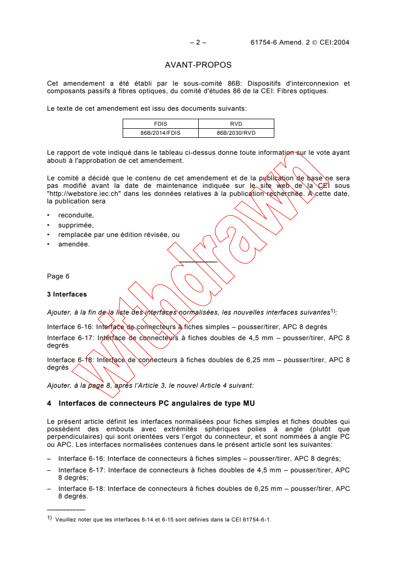
3 Interfaces
1)
Ajouter, à la fin de la liste des interfaces normalisées, les nouvelles interfaces suivantes :
Interface 6-16: Interface de connecteurs à fiches simples – pousser/tirer, APC 8 degrés
Interface 6-17: Interface de connecteurs à fiches doubles de 4,5 mm – pousser/tirer, APC 8
degrés
Interface 6-18: Interface de connecteurs à fiches doubles de 6,25 mm – pousser/tirer, APC 8
degrés
Ajouter, à la page 8, après l’Article 3, le nouvel Article 4 suivant:
4 Interfaces de connecteurs PC angulaires de type MU
Le présent article définit les interfaces normalisées pour fiches simples et fiches doubles qui
possèdent des embouts avec extrémités sphériques polies à angle (plutôt que
perpendiculaires) qui sont orientées vers l’ergot du connecteur, et sont nommées à angle PC
ou APC. Les interfaces normalisées contenues dans le présent article sont les suivantes:
– Interface 6-16: Interface de connecteurs à fiches simples – pousser/tirer, APC 8 degrés;
– Interface 6-17: Interface de connecteurs à fiches doubles de 4,5 mm – pousser/tirer, APC
8 degrés;
– Interface 6-18: Interface de connecteurs à fiches doubles de 6,25 mm – pousser/tirer, APC
8 degrés.
___________
1)
Veuillez noter que les interfaces 6-14 et 6-15 sont définies dans la CEI 61754-6-1.
61754-6 Amend. 2 IEC:2004 – 3 –
FOREWORD
This amendment has been prepared by subcommittee 86B: Fibre optic interconnecting devices
and passive components, of IEC technical committee 86: Fibre optics.
The text of this amendment is based on the following documents:
FDIS RVD
86B/2014/FDIS 86B/2030/RVD
Full information on the voting for the approval of this amendment can be found in the report on
voting indicated in the above table.
The committee has decided that the contents of this amendment and the base publication will
remain unchanged until the maintenance result date indicated on the IEC web site under
"http://webstore.iec.ch" in the data related to the specific publication. At this date, the
publication will be
• reconfirmed,
• withdrawn,
• replaced by a revised edition, or
• amended.
___________
Page 7
3 Interfaces
1)
Add, at the end of the list of standard interfaces, the following new interfaces :
Interface 6-16: Simplex plug connector interface – push/pull, APC 8 degrees
Interface 6-17: 4,5 mm duplex plug connector interface – push/pull, APC 8 degrees
Interface 6-18: 6,25 mm duplex plug connector interface – push/pull, APC 8 degrees
Add, on page 8, the following new Clause 4:
4 MU angled PC connector interfaces
This clause defines the standard interfaces for simplex and duplex plugs that have ferrules with
endfaces polished spherically at an angle (rather than perpendicularly) which are oriented to the
connector key, and are termed angled PC or APC. The standard interfaces contained in this
clause are the following:
– interface 6-16: simplex plug connector interface – push/pull, APC 8 degrees;
– interface 6-17: 4,5 mm duplex plug connector interface – push/pull, APC 8 degrees;
– interface 6-18: 6,25 mm duplex plug connector interface – push/pull, APC 8 degrees.
___________
1)
Please note that interfaces 6-14 and 6-15 are defined in IEC 61754-6-1.
– 4 – 61754-6 Amend. 2 CEI:2004
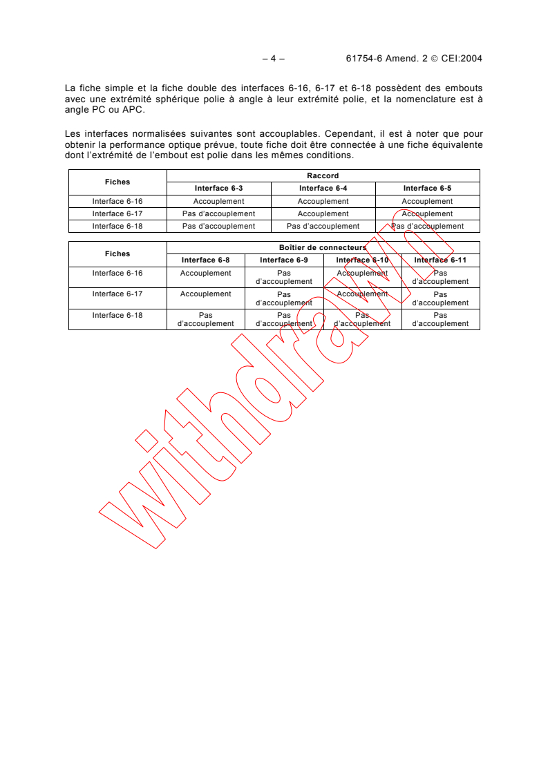
La fiche simple et la fiche double des interfaces 6-16, 6-17 et 6-18 possèdent des embouts
avec une extrémité sphérique polie à angle à leur extrémité polie, et la nomenclature est à
angle PC ou APC.
Les interfaces normalisées suivantes sont accouplables. Cependant, il est à noter que pour
obtenir la performance optique prévue, toute fiche doit être connectée à une fiche équivalente
dont l’extrémité de l’embout est polie dans les mêmes conditions.
Raccord
Fiches
Interface 6-3 Interface 6-4 Interface 6-5
Interface 6-16 Accouplement Accouplement Accouplement
Interface 6-17 Pas d’accouplement Accouplement Accouplement
Interface 6-18 Pas d’accouplement Pas d’accouplement Pas d’accouplement
Boîtier de connecteurs
Fiches
Interface 6-8 Interface 6-9 Interface 6-10 Interface 6-11
Interface 6-16 Accouplement Pas Accouplement Pas
d’accouplement d’accouplement
Interface 6-17 Accouplement Pas Accouplement Pas
d’accouplement d’accouplement
Interface 6-18 Pas Pas Pas Pas
d’accouplement d’accouplement d’accouplement d’accouplement
61754-6 Amend. 2 IEC:2004 – 5 –
The simplex and duplex plugs of interfaces 6-16, 6-17 and 6-18 have ferrules with an endface
polished spherically at an angle of their polished endface, and the nomenclature is angled PC or
APC.
The following standard interfaces are intermateable. It shall be noted however that in order to
obtain the designated optical performance, any plug shall be connected to a counterpart plug
whose ferrule end is polished to the same condition.
Adaptor
Plugs
Interface 6-3 Interface 6-4 Interface 6-5
Interface 6-16 Mate Mate Mate
Interface 6-17 Not Mate Mate Mate
Interface 6-18 Not Mate Not Mate Not Mate
Connector housing
Plugs
Interface 6-8 Interface 6-9 Interface 6-10 Interface 6-11
Interface 6-16 Mate Not Mate Mate Not Mate
Interface 6-17 Mate Not Mate Mate Not Mate
Interface 6-18 Not Mate Not Mate Not Mate Not Mate
– 6 – 61754-6 Amend. 2 CEI:2004
Cible de référence
optique
Embout
Manchon de couplage
Coupe transversale A-A
(1) Conique (2) Gradin
Vue agrandie de la partie antérieure
de l’embout (Après polissage, Note 1
du Tableau 14)
Projection de B
IEC 1384/04
Figure 14a – Interface de connecteur à fiche simple
61754-6 Amend. 2 IEC:2004 – 7 –
Optical datum
target
Ferrule
Coupling sleeve
Cross section A-A
(1) Conical (2) Step
Expanded view of ferrule endface
(After polishing, note 1 of Table 14)
Projected from B
IEC 1384/04
Figure 14a – Simplex plug connector interface
– 8 – 61754-6 Amend. 2 CEI:2004
Plan B
Embout
Plan A
Clé de guidage
Vue agrandie de la direction
(Après polissage)
Sommet
Plan de référence
PC angulaire
Géométrie d’extrémité de l’embout
(Vue agrandie de la direction D, après
polissage)
IEC 1385/04
Figure 14b – Interface de connecteur à fiche simple
61754-6 Amend. 2 IEC:2004 – 9 –
Plane B
Ferrule
Plane A
Guide key
Expanded view from C direction
(After polishing)
Vertex
Angled PC
reference plane
Ferrule endface geometry
(Expanded view from D direction, after
polishing)
IEC 1385/04
Figure 14b – Simplex plug connector interface
– 10 – 61754-6 Amend. 2 CEI:2004
Tableau 14 – Dimensions de l'interface du connecteur à fiche simple
Dimensions
Référence Notes
Minimum Principale Maximum
A 1,2485 mm 1,2495 mm 2
B 2,6 mm 2,7 mm
C 4,6 mm 4,8 mm
D 4,65 mm 4,75 mm
E 4,3 mm 4,4 mm
F 3,3 mm 3,4 mm
G 25° 35°
H 25° 35°
I 6,55 mm - 3
J 4,2 mm 4,5 mm 4
K 5,5 mm -
L 2,4 mm 2,5 mm
M 1,5 mm -
N 0,6 mm -
O 0,5 mm -
P 2,6 mm - 3
Q 1 mm 1,1 mm 3 et 5
R 2,65 mm 2,9 mm 3
S 5,5 mm 5,6 mm
T 4,3 mm 4,5 mm
U - 3,7 mm
V - 2,4 mm
W 6,5 mm 6,6 mm
AA 4,3 mm 4,4 mm
AB 3,85 mm 3,95 mm
AC 0,7 mm 0,9 mm
AD 0,2 mm - Rayon
AE 3 mm -
AF 2,2 mm 2,3 mm
EA - 90° - 6
EB 8°
EC 32,5° 45° 7
ED 0,6 mm 0,85 mm
EO 0,00 mm 0,05 mm 8
EP 5 mm 12 mm Rayon, 9
61754-6 Amend. 2 IEC:2004 – 11 –
Table 14 – Dimensions of the simplex plug connector interfaces
Dimensions
Reference Notes
Minimum Basic Maximum
A 1,2485 mm 1,2495 mm 2
B 2,6 mm 2,7 mm
C 4,6 mm 4,8 mm
D 4,65 mm 4,75 mm
E 4,3 mm 4,4 mm
F 3,3 mm 3,4 mm
G 25° 35°
H 25° 35°
I 6,55 mm - 3
J 4,2 mm 4,5 mm 4
K 5,5 mm -
L 2,4 mm 2,5 mm
M 1,5 mm -
N 0,6 mm -
O 0,5 mm -
P 2,6 mm - 3
Q 1 mm 1,1 mm 3 and 5
R 2,65 mm 2,9 mm 3
S 5,5 mm 5,6 mm
T 4,3 mm 4,5 mm
U - 3,7 mm
V - 2,4 mm
W 6,5 mm 6,6 mm
AA 4,3 mm 4,4 mm
AB 3,85 mm 3,95 mm
AC 0,7 mm 0,9 mm
AD 0,2 mm - Radius
AE 3 mm -
AF 2,2 mm 2,3 mm
EA - 90° - 6
EB 8°
EC 32,5° 45° 7
ED 0,6 mm 0,85 mm
EO 0,00 mm 0,05 mm 8
EP 5 mm 12 mm Radius, 9
– 12 – 61754-6 Amend. 2 CEI:2004
Tableau 14 (suite)
NOTE 1 Il faut que la forme de l’extrémité de l’embout corresponde à une des formes (1) ou (2) illustrées dans
la figure de la vue agrandie de la partie antérieure de l’embout (voir la Figure 14a).
NOTE 2 Un chanfrein ou rayon est autorisé jusqu'à une profondeur maximale de 0,5 mm par rapport à la partie
antérieure de l'embout.
NOTE 3 Il faut que le manchon de couplage puisse être déplacé vers la droite et vers la gauche. Ces
dimensions sont indiquées lorsque le manchon de couplage est déplacé dans la position située le plus à droite.
NOTE 4 La dimension J est indiquée pour la partie antérieure de la fiche quand elle n'est pas accouplée. On
remarque que l'embout peut être déplacé par une certaine force de compression axiale avec des extrémités en
contact direct et, de ce fait, la dimension J donnée est variable. Il faut que la force de compression de l'embout
soit comprise entre 5,5 N et 6,5 N lorsque la position de la cible de référence optique à partir de la référence X
est déplacée de 3,9 mm à 4,1 mm. De plus, il faut que la dimension J se réduise en dessous de 3,25 mm avec
une force de compression axiale relativement importante.
NOTE 5 Il faut que la position du côté droit de Q devienne la position du côté gauche par rapport au plan
défini par la référence X lorsque le manchon de couplage est déplacé vers sa position située la plus à gauche.
NOTE 6 La dimension EA est définie comme un angle entre deux plans: un plan, le plan A, traverse l'axe de
l'embout et l'axe de symétrie de la clé de la fiche de connecteur à extrémité angulaire. L'autre plan, le plan B,
passe par l'axe de l'embout et perpendiculairement au plan de référence PC angulaire.
NOTE 7 40° à 45° sont souhaitables pour minimiser les débris pour les connecteurs de fond de panier.
NOTE 8 La dimension EO est définie comme la distance entre le centre de l'embout et le sommet de l’extrémité
sphérique polie par rapport au plan de référence PC angulaire. Il faut que cette dimension soit mesurée aux
deux positions extrêmes lorsque l'embout subit une rotation dans le connecteur.
NOTE 9 Il faut que la dimension EP soit mesurée sur un diamètre de 0,25 mm autour de l’axe de l’embout.
61754-6 Amend. 2 IEC:2004 – 13 –
Table 14 (continued)
NOTE 1 The shape of the ferrule end must be one of shape (1) or (2) shown in the figure of expanded view of
ferrule endface (see figure 14a)
NOTE 2 A chamfer or radius is allowed to maximum depth of 0,5 mm from the ferrule endface.
NOTE 3 The coupling sleeve must be movable toward the right and the left directions. These dimensions are given
when the coupling sleeve is moved in its most right-direction position.
NOTE 4 The dimension J is given for the plug endface when not mated. It is noticed that the ferrule is movable by
a certain axial compression force with direct contacting endfaces, and therefore the dimension J is given variable.
Ferrule compression force must be 5,5 N to 6,5 N when the position of the optical datum target from the datum X is
moved in the range of 3,9 mm to 4,1 mm. In addition, the dimension J must become less than 3,25 mm with a
relatively large axial compression force.
NOTE 5 The right-side position of Q must become the left-side position to the plane defined by datum X when the
coupling sleeve is moved to its most left-direction position.
NOTE 6 Dimension EA is defined as an angle between two planes: one plane, plane A, passes through the axis of
the ferrule and axis of symmetry of the key of the angled endface connector plug. The other plane, plane B, passes
through the axis of the ferrule and the normal to the angled PC reference plane.
NOTE 7 40° to 45° are desirable to minimize debris for backplane connectors.
NOTE 8 Dimension EO is defined as a distance between the ferrule centre and the vertex of the spherically
polished endface relative to the angled PC reference plane. This dimension must be measured in both extreme
positions when the ferrule is rotated in the connector.
NOTE 9 Dimension EP must be measured over a diameter of 0,25 mm around the ferrule axis.
– 14 – 61754-6 Amend. 2 CEI:2004
Cible de référence
optique
Embout
Manchon de couplage
Coupe transversale A-A
(1) Conique (2) Gradin
Vue agrandie de la partie antérieure
de l’embout (Après polissage, Note 1
du Tableau 15)
Projection de B
IEC 1386/04
Figure 15a – Interface de connecteurs à fiches doubles de 4,5 mm
61754-6 Amend. 2 IEC:2004 – 15 –
Optical d
...