

IEC 61307:2026
(Main)Industrial microwave heating installations - Test methods for the determination of power output
General Information
- Abstract
IEC 61307:2026 specifies test methods for the determination of the efficiency of frequency conversion from the electrical input, and of the available and workload microwave output power in industrial microwave heating installations, as well as operational flexibility. This document is in principle applicable to industrial microwave heating equipment and installations in the frequency range from 300 MHz to 300 GHz but focused on the microwave ISM frequencies below 6 GHz. This document relates to industrial microwave heating equipment operating as intended by the manufacturer's specifications for normal operation. This document does not apply to appliances for household and similar use (covered by IEC 60335‑2‑25), commercial use (covered by IEC 60335-2-90 and IEC 60335‑2-110) or laboratory use (covered by IEC 61010-2-010). This fourth edition cancels and replaces the third edition published in 2011. This edition constitutes a technical revision.
This edition includes the following significant technical changes with respect to the previous edition:
a) it covers not only the standby and hibernation modes, but also start-up, standby and holding power consumption, as well as other aspects of operation flexibility;
b) more detailed descriptions of the aspects of microwave power, and handling of the A and B types of equipment.
- Status
- Published
- Publication Date
- 04-Aug-2026
- Technical Committee
- TC 27 - Industrial electroheating and electromagnetic processing
- Drafting Committee
- MT 23 - TC 27/MT 23
- Current Stage
- PPUB - Publication issued
- Start Date
- 05-Aug-2026
- Completion Date
- 04-Sep-2026
Buy Documents
REDLINE IEC 61307:2026 RLV - Industrial microwave heating installations - Test methods for the determination of power output
IEC 61307:2026 - Installations industrielles de chauffage par micro-ondes - Méthodes d'essai pour la détermination de la puissance de sortie
iec61307{ed4.0}en - Industrial microwave heating installations - Test methods for the determination of power output
Overview
IEC 61307:2026 defines standardized test methods for determining the power output and efficiency of industrial microwave heating installations. This international standard focuses on the performance and operational flexibility of microwave heating equipment operating primarily in the frequency range below 6 GHz, specifically within the Industrial, Scientific, and Medical (ISM) frequencies. It provides methodologies for measuring available and effective microwave output power, conversion efficiency, and specific aspects related to standby, start-up, and holding power consumption.
The standard applies to industrial microwave heating applications, such as drying, curing, and processing of materials, as used in manufacturing and industrial settings. It does not cover household appliances, commercial microwave ovens, or laboratory devices, as these are regulated by other IEC standards.
Key Topics
- Microwave Power Measurement: Procedures for measuring both available output power and actual power delivered to workloads using calorimetric and dummy load methods.
- Efficiency Determination: Guidelines for assessing frequency conversion efficiency and overall system efficiency, including all ancillary power-consuming components.
- Operational Modes: Testing requirements span cold start-up, standby, and holding operation, supporting a full evaluation of energy consumption patterns in industrial scenarios.
- Equipment Categories: Distinction between type A (separable generator and applicator) and type B (integrated generator and applicator) microwave equipment, with tailored testing approaches for each.
- Workload Testing: Recommendations for substituting practical workloads with artificial loads or water-based tests to ensure repeatable and comparable results.
- Power Loss Considerations: Identification and measurement of losses from impedance mismatching, cavity wall absorption, container transparency, and cross-coupling effects.
- Calorimetric Methods: Use of direct liquid water power measurements and drying of substitute loads for reliable power absorption assessment.
Applications
IEC 61307:2026 is crucial for manufacturers, operators, and testing laboratories involved in industrial microwave heating installations. Key practical applications include:
- Performance Verification: Ensures industrial microwave heating systems meet manufacturer specifications and regulatory requirements for output power and energy efficiency.
- Comparative Assessment: Offers standardized methods to compare different equipment or installations within the same class, supporting informed procurement or upgrade decisions.
- Energy Optimization: Identifies and quantifies power losses and operational inefficiencies, enabling targeted improvements for energy savings.
- Quality Assurance: Establishes consistent test procedures for acceptance, maintenance, and ongoing validation of industrial microwave equipment.
- Safety and Compliance: Supports adherence to international safety and electromagnetic compatibility regulations by enabling reliable measurement of all relevant power parameters.
Related Standards
Organizations implementing or referencing IEC 61307:2026 should also consider the following related standards:
- IEC 60519-6: Safety in installations for electroheating and electromagnetic processing – Particular requirements for high frequency dielectric and microwave heating and processing equipment.
- IEC 60335-2-25, IEC 60335-2-90, IEC 60335-2-110: Cover requirements for household, commercial, and specialized microwave ovens.
- IEC 61010-2-010: Addresses laboratory heating appliances.
- IEC 60050-841: International Electrotechnical Vocabulary - Industrial Electroheat.
- IEC 60705: Standardized testing method for microwave oven output power, referenced for household and smaller commercial units.
By using IEC 61307:2026, industry professionals gain a reliable framework for evaluating the output and efficiency of industrial microwave heating equipment, ensuring optimized performance, energy management, and regulatory compliance in their operations.
Relations
- Effective Date
- 31-Jan-2025
Buy Documents
REDLINE IEC 61307:2026 RLV - Industrial microwave heating installations - Test methods for the determination of power output
IEC 61307:2026 - Installations industrielles de chauffage par micro-ondes - Méthodes d'essai pour la détermination de la puissance de sortie
iec61307{ed4.0}en - Industrial microwave heating installations - Test methods for the determination of power output
Get Certified
Connect with accredited certification bodies for this standard

DVS-ZERT GmbH
German welding certification society.
CARES (UK Certification Authority for Reinforcing Steels)
UK certification for reinforcing steels and construction.
EWF/IIW (European/International Welding Federation)
International welding personnel certification.
Sponsored listings
Frequently Asked Questions
IEC 61307:2026 is a standard published by the International Electrotechnical Commission (IEC). Its full title is "Industrial microwave heating installations - Test methods for the determination of power output". This standard covers: IEC 61307:2026 specifies test methods for the determination of the efficiency of frequency conversion from the electrical input, and of the available and workload microwave output power in industrial microwave heating installations, as well as operational flexibility. This document is in principle applicable to industrial microwave heating equipment and installations in the frequency range from 300 MHz to 300 GHz but focused on the microwave ISM frequencies below 6 GHz. This document relates to industrial microwave heating equipment operating as intended by the manufacturer's specifications for normal operation. This document does not apply to appliances for household and similar use (covered by IEC 60335‑2‑25), commercial use (covered by IEC 60335-2-90 and IEC 60335‑2-110) or laboratory use (covered by IEC 61010-2-010). This fourth edition cancels and replaces the third edition published in 2011. This edition constitutes a technical revision. This edition includes the following significant technical changes with respect to the previous edition: a) it covers not only the standby and hibernation modes, but also start-up, standby and holding power consumption, as well as other aspects of operation flexibility; b) more detailed descriptions of the aspects of microwave power, and handling of the A and B types of equipment.
IEC 61307:2026 specifies test methods for the determination of the efficiency of frequency conversion from the electrical input, and of the available and workload microwave output power in industrial microwave heating installations, as well as operational flexibility. This document is in principle applicable to industrial microwave heating equipment and installations in the frequency range from 300 MHz to 300 GHz but focused on the microwave ISM frequencies below 6 GHz. This document relates to industrial microwave heating equipment operating as intended by the manufacturer's specifications for normal operation. This document does not apply to appliances for household and similar use (covered by IEC 60335‑2‑25), commercial use (covered by IEC 60335-2-90 and IEC 60335‑2-110) or laboratory use (covered by IEC 61010-2-010). This fourth edition cancels and replaces the third edition published in 2011. This edition constitutes a technical revision. This edition includes the following significant technical changes with respect to the previous edition: a) it covers not only the standby and hibernation modes, but also start-up, standby and holding power consumption, as well as other aspects of operation flexibility; b) more detailed descriptions of the aspects of microwave power, and handling of the A and B types of equipment.
IEC 61307:2026 is classified under the following ICS (International Classification for Standards) categories: 25.180.10 - Electric furnaces. The ICS classification helps identify the subject area and facilitates finding related standards.
IEC 61307:2026 has the following relationships with other standards: It is inter standard links to IEC 61307:2011. Understanding these relationships helps ensure you are using the most current and applicable version of the standard.
IEC 61307:2026 is available in PDF format for immediate download after purchase. The document can be added to your cart and obtained through the secure checkout process. Digital delivery ensures instant access to the complete standard document.
Standards Content (Sample)
IEC 61307 ®
Edition 4.0 2026-08
INTERNATIONAL
STANDARD
REDLINE VERSION
Industrial microwave heating installations - Test methods for the determination
of power output
ICS 25.180.10 ISBN 978-2-8327-1436-2
All rights reserved. Unless otherwise specified, no part of this publication may be reproduced or utilized in any form or
by any means, electronic or mechanical, including photocopying and microfilm, without permission in writing from either
IEC or IEC's member National Committee in the country of the requester. If you have any questions about IEC copyright
or have an enquiry about obtaining additional rights to this publication, please contact the address below or your local
IEC member National Committee for further information.
IEC Secretariat Tel.: +41 22 919 02 11
3, rue de Varembé info@iec.ch
CH-1211 Geneva 20 www.iec.ch
Switzerland
About the IEC
The International Electrotechnical Commission (IEC) is the leading global organization that prepares and publishes
International Standards for all electrical, electronic and related technologies.
About IEC publications
The technical content of IEC publications is kept under constant review by the IEC. Please make sure that you have the
latest edition, a corrigendum or an amendment might have been published.
IEC publications search - IEC Products & Services Portal - products.iec.ch
webstore.iec.ch/advsearchform Discover our powerful search engine and read freely all the
The advanced search enables to find IEC publications by a publications previews, graphical symbols and the glossary.
variety of criteria (reference number, text, technical With a subscription you will always have access to up to date
committee, …). It also gives information on projects, content tailored to your needs.
replaced and withdrawn publications.
Electropedia - www.electropedia.org
The world's leading online dictionary on electrotechnology,
IEC Just Published - webstore.iec.ch/justpublished
Stay up to date on all new IEC publications. Just Published containing more than 22 500 terminological entries in English
details all new publications released. Available online and and French, with equivalent terms in 25 additional languages.
once a month by email. Also known as the International Electrotechnical Vocabulary
(IEV) online.
IEC Customer Service Centre - webstore.iec.ch/csc
If you wish to give us your feedback on this publication or
need further assistance, please contact the Customer
Service Centre: sales@iec.ch.
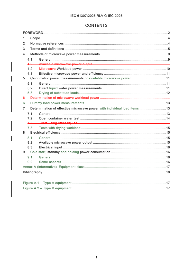
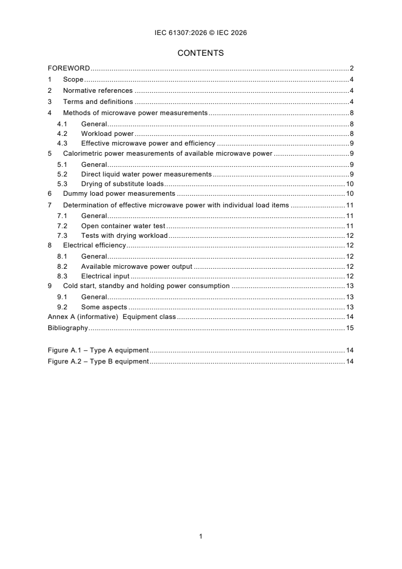
CONTENTS
FOREWORD . 2
1 Scope . 4
2 Normative references . 4
3 Terms and definitions . 5
4 Methods of microwave power measurements . 9
4.1 General . 9
4.2 Available microwave power output .
4.2 Microwave Workload power . 10
4.3 Effective microwave power and efficiency . 11
5 Calorimetric power measurements of available microwave power . 11
5.1 General . 11
5.2 Direct liquid water power measurements . 11
5.3 Drying of substitute loads . 12
6 Determination of microwave workload power .
6 Dummy load power measurements . 13
7 Determination of effective microwave power with individual load items . 13
7.1 General . 13
7.2 Open container water test . 14
7.3 Tests using other liquids .
7.3 Tests with drying workload . 15
8 Electrical efficiency . 15
8.1 General . 15
8.2 Available microwave power output . 15
8.3 Electrical input . 16
9 Cold start, standby and holding power consumption . 16
9.1 General . 16
9.2 Some aspects . 16
Annex A (informative) Equipment class . 17
Bibliography . 18
Figure A.1 – Type A equipment . 17
Figure A.2 – Type B equipment . 17
INTERNATIONAL ELECTROTECHNICAL COMMISSION
____________
Industrial microwave heating installations -
Test methods for the determination of power output
FOREWORD
1) The International Electrotechnical Commission (IEC) is a worldwide organization for standardization comprising
all national electrotechnical committees (IEC National Committees). The object of IEC is to promote international
co-operation on all questions concerning standardization in the electrical and electronic fields. To this end and
in addition to other activities, IEC publishes International Standards, Technical Specifications, Technical Reports,
Publicly Available Specifications (PAS) and Guides (hereafter referred to as "IEC Publication(s)"). Their
preparation is entrusted to technical committees; any IEC National Committee interested in the subject dealt with
may participate in this preparatory work. International, governmental and non-governmental organizations liaising
with the IEC also participate in this preparation. IEC collaborates closely with the International Organization for
Standardization (ISO) in accordance with conditions determined by agreement between the two organizations.
2) The formal decisions or agreements of IEC on technical matters express, as nearly as possible, an international
consensus of opinion on the relevant subjects since each technical committee has representation from all
interested IEC National Committees.
3) IEC Publications have the form of recommendations for international use and are accepted by IEC National
Committees in that sense. While all reasonable efforts are made to ensure that the technical content of IEC
Publications is accurate, IEC cannot be held responsible for the way in which they are used or for any
misinterpretation by any end user.
4) In order to promote international uniformity, IEC National Committees undertake to apply IEC Publications
transparently to the maximum extent possible in their national and regional publications. Any divergence between
any IEC Publication and the corresponding national or regional publication shall be clearly indicated in the latter.
5) IEC itself does not provide any attestation of conformity. Independent certification bodies provide conformity
assessment services and, in some areas, access to IEC marks of conformity. IEC is not responsible for any
services carried out by independent certification bodies.
6) All users should ensure that they have the latest edition of this publication.
7) No liability shall attach to IEC or its directors, employees, servants or agents including individual experts and
members of its technical committees and IEC National Committees for any personal injury, property damage or
other damage of any nature whatsoever, whether direct or indirect, or for costs (including legal fees) and
expenses arising out of the publication, use of, or reliance upon, this IEC Publication or any other IEC
Publications.
8) Attention is drawn to the Normative references cited in this publication. Use of the referenced publications is
indispensable for the correct application of this publication.
9) IEC draws attention to the possibility that the implementation of this document may involve the use of (a)
patent(s). IEC takes no position concerning the evidence, validity or applicability of any claimed patent rights in
respect thereof. As of the date of publication of this document, IEC had not received notice of (a) patent(s), which
may be required to implement this document. However, implementers are cautioned that this may not represent
the latest information, which may be obtained from the patent database available at https://patents.iec.ch. IEC
shall not be held responsible for identifying any or all such patent rights.
This redline version of the official IEC Standard allows the user to identify the changes made
to the previous edition IEC 61307:2011. A vertical bar appears in the margin wherever a change
has been made. Additions are in green text, deletions are in strikethrough red text.
IEC 61307 has been prepared by IEC technical committee 27: Industrial electroheating and
electromagnetic processing. It is an International Standard.
This fourth edition cancels and replaces the third edition published in 2011. This edition
constitutes a technical revision.
This edition includes the following significant technical changes with respect to the previous
edition:
a) it covers not only the standby and hibernation modes, but also start-up, standby and holding
power consumption, as well as other aspects of operation flexibility;
b) more detailed descriptions of the aspects of microwave power, and handling of the A and B
types of equipment.
The text of this International Standard is based on the following documents:
Draft Report on voting
27/1243/FDIS 27/1247/RVD
Full information on the voting for its approval can be found in the report on voting indicated in
the above table.
The language used for the development of this International Standard is English.
This document was drafted in accordance with ISO/IEC Directives, Part 2, and developed in
accordance with ISO/IEC Directives, Part 1 and ISO/IEC Directives, IEC Supplement, available
at www.iec.ch/members_experts/refdocs. The main document types developed by IEC are
described in greater detail at www.iec.ch/publications.
The committee has decided that the contents of this document will remain unchanged until the
stability date indicated on the IEC website under webstore.iec.ch in the data related to the
specific document. At this date, the document will be
– reconfirmed,
– withdrawn, or
– revised.
1 Scope
This document specifies test methods for the determination of the available microwave output
power and the efficiency of frequency conversion from the electrical input, and of the available
and workload microwave output power in industrial microwave heating installations, as well as
operational flexibility.
This standard also specifies test methods for assessing the microwave power deposition in the
microwave workload – the microwave workload power, in microwave-only installations.
This document is in principle applicable to industrial microwave heating equipment and
installations in the frequency range from 300 MHz to 300 GHz but focussed on the microwave
ISM frequencies below 6 GHz.
This document relates to industrial microwave heating equipment operating under normal load
as intended by the manufacturer's specifications for normal operation.
This document does not apply to appliances for household and similar use (covered by
IEC 60335-2-25 [1] ), commercial use (covered by IEC 60335-2-90 [2] and IEC 60335-2-110 [3])
or laboratory use (covered by IEC 61010-2-010 [4]).
2 Normative references
The following documents are referred to in the text in such a way that some or all of their content
constitutes requirements of this document. For dated references, only the edition cited applies.
For undated references, the latest edition of the referenced document (including any
amendments) applies.
IEC 60050-221:1990, International Electrotechnical Vocabulary – Chapter 221: Magnetic
materials and components
Amendment 1(1993)
Amendment 2 (1999)
Amendment 3 (2007)
IEC 60050-841:2004, International Electrotechnical Vocabulary (IEV) - Part 841: Industrial
electroheat
IEC 60050-726:1982, International Electrotechnical Vocabulary – Chapter 726: Transmission
lines and waveguides
IEC 60519-6, Safety in electroheat installations for electroheating and electromagnetic
processing - Part 6: Specifications for safety in industrial microwave heating equipment
Particular requirements for high frequency dielectric and microwave heating and processing
equipment
___________
Numbers in square brackets refer to the Bibliography.
3 Terms and definitions
For the purposes of this document, the terms and definitions given in IEC 60519-6,
IEC 60050-841 and the following apply.
ISO and IEC maintain terminology databases for use in standardization at the following
addresses:
– IEC Electropedia: available at https://www.electropedia.org/
– ISO Online browsing platform: available at https://www.iso.org/obp
3.1
microwave heating equipment
assembly of electrical and mechanical devices intended for the transfer of microwave energy to
the microwave load workload and comprising, in general, power supplies, microwave generators
or microwave generator assemblies with cooling arrangements and circulators if used,
microwave applicators or cavities with ventilation arrangements if used, interconnecting cables
and waveguides, control circuitry, and means for transporting the microwave load workload if
used
[IEC 60050-841:2004, 841-29-06, modified]
3.2
equipment class
group within a type of equipment, using the same principle for processing of the workload either
type A or type B
SEE: Annex A.
Note 1 to entry: An example of type is microwave equipment, and a class example is such equipment for wood
drying heating in a specified capacity interval using the ISM frequency 2,45 GHz.
3.3
type A equipment
equipment with the microwave generator (frequency converter part) independent
of, or separable from, the applicator to which the microwave power is provided
EXAMPLE A coaxial feeder, a waveguide junction.
Note 1 to entry: This allows the integration of a circulator as protection for the magnetron against reflected
microwave power as well as a tuner to minimize microwave reflection for proper tuning/matching.
Note 2 to entry: Any ancillary microwave generator components such as cathode heater transformers and the
generator cooling system are also separable.
3.4
type B equipment
equipment with the microwave generator (frequency converter part) being directly
coupled to the applicator, without a transmission line in between
3.5
electrical conversion efficiency of microwave heating equipment
quotient between the available microwave power output and the electrical input to the mains
frequency power supply or microwave generator assembly, at power settings for normal
intended operation
3.6
overall efficiency
efficiency of the complete system including all ancillary power consumption except for workload
transport
EXAMPLE Cooling fans or pumps and other cooling systems.
3.7
microwave generator
source used to produce electromagnetic energy in the frequency range from 300 MHz to
300 GHz
[IEC 60050-841:2004, 841-29-16]
Note 1 to entry: In the context of this document, the microwave generator is only the component where the
frequency conversion takes place. See 3.2.
3.8
microwave generator assembly
part of the microwave heating equipment comprising an apparatus producing microwave energy
and its associated transmission line output port
Note 1 to entry: The assembly includes the microwave generator, the power supply of the microwave generator and
its ancillary and control circuits. If a circulator is used, it is also included.
Note 2 to entry: Microwave heating equipment containing a microwave generator assembly was classified as type
A in earlier editions of IEC 61307; equipment where a transmission line output port is not available was classified as
type B.
3.9
microwave applicator
structure which applies the microwave energy to the load
[IEC 60050-841:2004, 841-29-11]
3.10
microwave cavity
space enclosed by inner metal walls and a door or an access opening and in which the
microwave load is placed
[IEC 60050-841:2004, 841-29-19, modified]
3.11
microwave enclosure
structure which is intended to confine the microwave energy to a defined region
EXAMPLE A cavity, door seals and waveguides.
[IEC 60050-841:2004, 841-29-20]
3.12
microwave workload
object to be treated by microwaves
NOTE Workload containers are not a part of the microwave workload but of the microwave load.
Note 1 to entry: The workload includes any container, holder or other device necessary for the processing and
which is directly or indirectly subjected to the output power. The processed object/material as such is also called the
load.
[IEC 60050-841:2004, 841-29-13]
3.13
normal load
nominal microwave load workload at full rated microwave output power as specified by the
manufacturer's documentation
3.14
normal operation
range of microwave output power with the normal loads in allowable working conditions of the
microwave heating equipment, as specified by the manufacturer's documentation
equipment operation under normal load conditions under nominal ambient conditions including
the nominal electrical supply network
3.15
intended operation
range of microwave output and allowable electrical input conditions, for intended workloads as
specified by the manufacturer
Note 1 to entry: Several setting combinations are typically specified.
3.16
performance
degree to which the intended functions, including energy or
power consumption and output as well as the result of the treatment of the workload are
accomplished
3.17
equipment capacity
measure of the production rate capability of equipment when in intended normal operation
EXAMPLE Flow, mass or volume.
Note 1 to entry: The equipment capacity does not refer to the volume of the available cavity space.
3.18
cold start-up
process by which the equipment is energised into hot standby operation from the cold state,
including all other start-up operations which enable the equipment to run under intended
operation
Note 1 to entry: This mode of operation applies to cases where there is a significant energy consumption needed
for obtaining a state of the equipment allowing the actual processing of the workload.
3.19
holding power
electric power consumption during which the workload is kept in the treatment chamber at a
specified temperature
Note 1 to entry: The temperature is typically maintained for a period of time, intended to equalize the workload
temperature.
Note 2 to entry: This mode of operation is not applicable for certain types of electroheating equipment.
3.20
standby (mode of) operation
condition allowing immediate normal operation
standby mode of operation
condition of zero output power between periods of continuous intended power operation with
power output
NOTE 1 This mode typically occurs immediately before and after normal operation.
Note 1 to entry: This mode of operation allows immediate start of full power operation.
Note 2 to entry: If the treatment of the workload requires non-ambient conditions such as elevated temperature,
this is maintained by non-microwave means.
Note 3 to entry: "immediate" means a time period consistent with normal loading, unloading or replacement of the
workload.
NOTE 4 The magnetron cathode heater circuit may be switched on in this mode of operation.
3.21
hot standby operation
mode of operation of the installation occurring immediately after normal operation
EXAMPLE Type A equipment with circulator protection.
Note 1 to entry: This mode of operation of the equipment is with its hot state remaining, without workload, and with
the means of operation ready for prompt normal operation.
3.22
calorimetric power meter
calorimeter power meter
calorimetric measurements
power meter which uses temperature rise in a medium as a means of measuring absorbed
power
method of measurement of power which uses the temperature rise in a medium as a means of
measuring absorbed power
Note 1 to entry: A different kind of calorimetric measurements uses the enthalpy of evaporation of water.
Note 2 to entry: The medium, typically water, is either the power-absorbing agent or has heat transferred to it from
a power-absorbing element.
[IEC 60050-726:1982, 726-21-10]
3.23
circulator
passive device having three or more ports in which the power entering any port is transmitted
to the next port according to a given order of sequence
Note 1 to entry: When an absorbing load is installed on the reflected power port of the circulator, the magnetron is
protected against reflected microwave power.
NOTE The typical forms are junction circulators [IEC 60050-221:1990, 221-05-14] of the T junction
[IEC 60050-726:1982, 726-17-12] or Y junction [IEC 60050-726:1982, 726-17-13].
[IEC 60050-221:1990, 221-05-11, modified]
3.24
insertion loss
loss resulting from the insertion of a network into a transmission system, the ratio of the power
delivered to that part of the system following the network, before insertion of the network, to the
power delivered to that same part after insertion of the network
Note 1 to entry: The insertion loss is generally expressed in decibels.
[IEC 60050-726:1982, 726-06-07]
3.25
isolator
two-port device having much greater attenuation in one direction of propagation
than in the opposite direction
Note 1 to entry: An isolator is often used to prevent return reflections along a transmission path.
3.26
microwave tuner
adjustable device which can match the applicator impedance to the magnetron, intended to
improve the efficiency of the microwave heating equipment
3.27
cross coupling
appearance of undesired microwave energy in a microwave generator
or the transmission line output port of a microwave generator assembly caused by one or several
other microwave generators or microwave generator assemblies
3.6
isolation (of a three-port circulator)
reverse attenuation between the main output port and main input port, with all ports being
impedance matched
NOTE 1 The isolation should not be confused with the reverse loss occurring between adjacent ports.
NOTE 2 This is a special case of cross coupling of a circulator [IEC 60050-726:1982, 726-16-06].
3.7
means of access
all structural features of the microwave heating equipment which can be opened or removed
without the use of a tool to provide access to the interior of the microwave applicator or
microwave cavity
3.14
microwave load
objects introduced into the applicator or cavity, or put in the intended position near an open
applicator
[IEC 60050-841:2004, 841-29-12]
3.15
microwave transparency
property of a material having negligible absorption and reflection of microwaves
NOTE The relative permittivity of a microwave transparent material is usually less than 7 and the loss factor is
usually less than 0,015. However, if the microwave workload has a low loss factor, more stringent requirements
apply.
[IEC 60050-841:2004, 841-29-14, modified]
4 Methods of microwave power measurements
4.1 General
Three different methods are described. All tests are to be carried out under conditions which
do not exceed intended operation. Several methods are described in Subclauses 5.2 and 5.3,
and Clause 7. Their applicability depends on the microwave frequency and power level, and if
the equipment comprises a separate microwave generator assembly.
There are two basic equipment layouts: types A and B, as defined in 3.3 and 3.4, and illustrated
in Figure A.1 and Figure A.2 in Annex A. The separation of the microwave oscillator from the
microwave applicator part in type A equipment allows more detailed investigations of various
system properties than what is possible with type B equipment.
– The available microwave power output is the maximum rated from the generator.
Subclause 5.2 is applicable for most types of equipment either type A or type B. For type A
equipment with microwave power output less than 1 kW, dummy loads can be used, and
this is described in Clause 6. Measurements of the available microwave power in type B
drying processes are more complicated and are described in 5.3.
– The effective microwave power is dealt with in Clause 7 and provides a more practical value.
Workloads which heat in a similar way to those used in the actual processing under practical
conditions are used.
– The rated/available microwave power and its test conditions shall be described in the
operation manual/instruction for use.
NOTE 1 Since the wavelength of frequencies above about 20 GHz is very short, the power deposition may be is
then typially of the irradiation type with a short penetration depth. With frequencies in the low end of the microwave
band at 300 MHz, water may is not be useable with the calorimetric method, and some of the methods of measuring
microwave power deposition in this document may are generally not be applicable, since properties of microwave
workloads will then be highly variable during the heating process. In the low end of the microwave band at 300 MHz,
the microwave absorption capability of loads may be highly variable during the heating process, large load masses
may be needed, and representative artificial liquid loads for calorimetry may be difficult to use. In general, large load
masses are often needed, and there are quite few representative artificial liquid loads for calorimetry.
NOTE 2 There are variabilities in the microwave absorption capability of microwave loads, and in particular the
unevenness of heating of these. Therefore, it is crucial to treat with care the microwave workload power data or the
effective microwave power data with a substitute liquid load obtained according to this document should be treated
with care. Power data is, however, important and objective factors related to the overall energy utilisation efficiency
are by that also a performance factor.
NOTE 3 A method for measuring the microwave power output in household and microwave ovens is specified in
IEC 60705 [5]. It uses a large water load, with compensation of heat capacity of the container and of heat exchange
with ambient. Technically, the method gives what is defined as the available microwave power output in this
document.
4.2 Available microwave power output
Measurements at the microwave generator assembly output port give the available microwave
power output (see Clause 5).
4.2 Microwave Workload power
Calorimetric measurements in a normal load, including the power losses in any containers for
the microwave workload, give the microwave workload power (see Clause 6).
This is the amount of power required to achieve an aimed enthalpy change in the microwave
workload within a fixed period of time. It depends on the type of microwave workload, the change
of its complex permittivity with temperature, as well as any workload containers or supports,
and the design of the microwave applicator or cavity.
The workload power is the power delivered to the normal workload under normal operation.
However, there are typically difficulties in assessing the actual absorbed energy in the workload
under practical dynamic conditions, so calorimetric measurements are instead used, under
conditions allowing a higher accuracy in the determination of power absorption.
The available microwave power output is always larger than the microwave workload power,
due to some or all of the following power loss mechanisms:
– impedance mismatching of the microwave generator;
– microwave enclosure cavity or applicator metal surface losses;
– absorption by imperfect microwave transparency of containers for the workload and any
other ancillary objects in the microwave enclosure;
– microwave leakage out of the microwave enclosure;
– power losses due to cross coupling.
NOTE 1 Measuring the forward microwave power and the reflected microwave power enables the calculation of the
absorbed microwave power for the workload by simple subtraction of the reflected power from the forward power by
using an isolator or a circulator.
NOTE 2 Detectors in an isolator or in the input (first) and third arm in a circulator are then used.
4.3 Effective microwave power and efficiency
Typically, actual practical microwave workloads are not well suited for calorimetric accurate
measurements of the absorbed power. Liquid substitutes are then used in calorimetric
measurements are then used and give the effective microwave power dealt with in Clause 7
(see Clause 7 and Clause 8).
Drying processes are dynamic, due to the microwave properties of the workload varying during
the process. Heating-up and evaporative weight losses can then be used as an alternative
calorimetric measurement, and calculated as absorbed energy over time, using the enthalpy
properties of the water being lost in the process and the heating-up of the dry parts of the
workload or substitute.
5 Calorimetric power measurements of available microwave power
5.1 General
Only the principles are outlined in this document. The applied measurement instrumentation
and use shall conform to known engineering techniques. Water is the directly or indirectly power-
absorbing substance.
5.2 Direct liquid water power measurements
It is important that any directly power-absorbing water has a microwave absorption capability
and load geometry which provides a good and essentially temperature independent impedance
matching over the actually used temperature interval. A sodium chloride solution with specific
conductivity between 200 µS/cm and 600 µS/cm shall be used for the direct absorption at
frequencies below 900 MHz.
The calorimetric power meter typically consists of a waveguide section, equipped with a
microwave transparent tube through which the water can flow. The water shall be thoroughly
mixed. The recommended water flow rate is about 1 l/min for each kilowatt but not less than
0,5 l/min. The difference between the outlet and inlet temperature shall be at least 10 K.
The inlet temperature of the water shall not exceed 35 °C, and the outlet temperature shall not
exceed 60 °C. However, for microwave power levels less than 3 kW, these temperatures should
be on both sides of the ambient temperature, to reduce heat loss errors.
Under operating conditions, the voltage standing wave ratio (VSWR) as measured by a network
analyser with a matched waveguide transition or an equivalent measurement device replacing
the microwave generator assembly and within the water temperature interval specified above,
shall not exceed 1,25.
If a circulator is used, its isolation shall be greater than 20 dB and the impedance matching of
the circulator with dissipative termination is to comply with this subclause.
The water flow shall be monitored, for instance by means of flow interlock switches, to avoid
the formation of steam which may can lead to eruption.
The power dissipated in the water is measured directly or compared with a calibrated heated
water standard.
The measurement shall be carried out only when the flow rate is stable, and both the microwave
generator and calorimetric load are operating under stable conditions. It is necessary to use
high-accuracy thermometers and flowmeters to ensure that the inaccuracy of power output
measurement is less than 5 %.
The available microwave power output P is calculated from Formula (1):
4 187⋅ QT⋅∆
P= (1)
where
P is the available microwave power output, in W;
-1 -1
Q is the water flow rate, in kg/min; the factor 4 187 is its specific heat in Jkg K , and 60 is
a factor resulting from units applied;
∆T is the temperature difference in K between the water outlet and inlet temperature.
NOTE If the microwave generator assembly contains a circulator with a dissipative termination in the third arm
protecting the microwave generator (e.g. by a water termination), this may can be used as a calorimetric power meter
by short-circuiting the load port second arm. It is then to be noted that twice the insertion loss applies for this
measurement, but not the circulator insertion loss is included in the evaluation for determination of the available
microwave power output.
5.3 Drying of substitute loads
A good and essentially temperature independent impedance matching over the actually used
temperature interval is not assumed. This means that the whole intended drying process shall
typically be reasonably representative. Test conditions then become different in continuous and
batch processing. The following should be observed:
– the choice of test load should be such that its microwave absorption capability during the
processing is reasonably similar to that of the normal load;
– variable microwave output power densities applied under normal operation shall also be
applied to the test load during the processing of the individual load items;
– influences on energy transfer to the test load by the temperature and humidity of the air in
the processing region;
– power losses due to cross coupling.
NOTE It is assumed that he starting conditions are representative of the normal load conditions.
6 Determination of microwave workload power
This test is applicable only if the normal load is well specified with regard to specific heat and
temperature rise in the process. Furthermore, it shall be possible to accurately measure the
average temperature rise after processing. If the set-up is suspected to provide an inaccuracy
of more than 5 % of the final result, the method described in Clause 5 or Clause 7 is instead
used.
NOTE Typically, accurate tests according to this clause can be made only in continuous processing of pumpable
workloads. These loads are representative only if their microwave properties are similar to those of the normal load.
The input temperature T (°C) of the microwave workload is measured. During steady-state
in
processing, a suitable length of processed microwave workload exiting the microwave heating
equipment during a predetermined time t (s) is quickly taken out as sample and thermal
insulation is provided. Temperature equilibration is then accomplished by either forced
convection (stirring or kneading of the sample) or by internal heat conduction, after which the
output temperature Tout and the mass m of the sample are measured. Its specific heat c has
been pre-determined.
The microwave workload power P is then calculated from the following equation:
W
(T − T ) ⋅ c⋅ m
out in
P = (2)
w
t
where
P is the microwave workload power, in W;
W
T is the output temperature, in °C;
out
T is the input temperature, in °C;
in
c is the specific heat of the workload, in J/(kg · K);
m is the mass of the sample in kg;
t is the sampling time, in s, during which the mass m of the sample is taken out from the
microwave heating equipment.
6 Dummy load power measurements
This is a special test which avoids the accuracy-reducing use of typical practical workloads, as
well as applicators or cavities for these measurements. It should not be confused with the
effective microwave power tests.
The dummy load is an artificial item with known thermal properties, designed to accurately
record the rate of increase of the absorbed or available output energy. Alternatively, measuring
the internal field strength in the dummy load device using such a capability may be used. The
absorbing part of the dummy load is typically matched by a microwave tuner to a low-reactance
termination, cooled by natural air convection, by forced air or by water. It is generally connected
to the microwave generator or generator assembly by a 50 Ω coaxial feeder, or by a TE10
waveguide. At low power levels, natural air convection is applied and at higher power levels up
to about 2 kW of forced air cooling can be applied.
NOTE Applicable dummy loads with a two-port design are commercially available, providing a calibrated insertion
loss at levels of −30 dB to −60 dB, suitable for the use of a commercially available power meter at its output port.
It is necessary to use high-accuracy components and instruments, to ensure that the inaccuracy
of power output measurement is less than 5 %.
7 Determination of effective microwave power with individual load items
7.1 General
The tests in Clause 7 are applicable in cases where the normal load cannot be well specified
with regard to specific heat, consists of individual items, or the process is for other reasons not
suitable for power determinations according to Clause 5. The normal load is replaced by an
artificial load, intended to have dielectric properties and geometries which result in reasonably
similar microwave absorption properties as in the normal load.
In the case of uncertainties with regard to the representativity suitability and equivalence of the
chosen artificial load, a network analyser is to be used to determine the impedance mismatches
with the normal load or a suitable substitute used as microwave workload and the artificial load,
respectively. The resulting calculated deviation in reflected power should not exceed 10 % of
the transmitted power, unless the microwave absorption capability of the normal load is very
difficult to characterise or varies significantly during processing. The estimated inaccuracy shall
be presented with the calculated effective microwave power.
Measuring devices including workload containers shall not be affected by electromagnetic fields,
unless explicitly specified or accepted by the manufacturer. The choice of measurement method
and the results shall be described in a document, with a reference to this document.
An indication shall also be given in the instructions for use that changes in the loading
conditions during the intended use typically have an influence on the efficiency of the microwave
heating equipment.
7.2 Open container water test
NOTE 1 A water load test is used for household and commercial microwave ovens, using 1 000 g of cold water in
a room temperature container, with the water being heated by only about 20 K. The power is calculated using
Formula (1) in 5.2, and is labelled microwave power output.
The water shall be placed in thin wall open containers, manufactured from a microwave
transparent material.
The amount of water shall be at least 0,5 l for each kilowatt of microwave generator power to
which it is exposed, and the height of the water column shall be at least 25 mm. Containers
should be distributed with a spacing such that at least 40 % of the available area within the
microwave enclosure is covered, unless specific patterns are specified by the manufacturer.
Due to possible effects of cross coupling between multiple microwave generators or microwave
generator assemblies, the test shall be made with a number of simultaneously operating
microwave generators or microwave generator assemblies and such large areas covered by the
containers that any such influence is included in the test result.
NOTE 2 Batch equipment and equipment considered to be of multimode or irradiation character and intended for
processing of loads significantly higher than 50 mm, may can be tested with single or multiple containers each taking
several litres.
As the water temperature increases by approximately 14 K per minute per litre of water for each
kilowatt of dissipated power in it, the processing time for the test is typically significantly shorter
than with the normal load. This is to avoid heat losses to the ambient surroundings, in particular
by evaporation. It shall be noted that if stable conditions may are not be obtained, any possibly
errors resulting due to such losses shall be recorded.
The heat capacity of those parts of the containers which are heated by the water shall be used
for corrections in the calculations of effective microwave power, using the energy deposited in
both.
7.3 Tests using other liquids
If the microwave heating equipment is intended for processing normal loads with a low moisture
content such as wood, some types of ceramics, resins or paper, or normal loads having a small
or inhomogeneous particulate structure, the dielectric properties of water may not be sufficiently
representative.
NOTE 1 The real permittivity of water is very high and its loss factor may be too low at frequencies below or even
at the ISM frequency 2 450 MHz, to be representative for the power absorption characteristics of the normal load.
Adding sodium chloride may result in edge overheating and subsequent power losses by evaporation at 2 450 MHz.
Additionally, the high real permittivity of water may result in a reduction of power absorption by stronger wave
reflections at the surface than for microwave workloads with lower real permittivity and a more uneven top surface.
Particularly in microwave heating equipment with separated multiple microwave applicators each having one or some
few microwave generators or microwave generator assemblies delivering some few kilowatts of available microwave
power output, and intended for drying or similar treatment of small microwave workloads, it is recommended to use
liquids having a low real permittivity and good microwave absorption capability.
NOTE 2 Glycerol may be used. Technical glycerol contains about 15 % water and may be acceptable, but its thermal
data should then be checked
...
IEC 61307 ®
Edition 4.0 2026-08
NORME
INTERNATIONALE
Installations industrielles de chauffage par micro-ondes - Méthodes d'essai pour
la détermination de la puissance de sortie
ICS 25.180.10 ISBN 978-2-8327-1429-4
Droits de reproduction réservés. Sauf indication contraire, aucune partie de cette publication ne peut être reproduite ni
utilisée sous quelque forme que ce soit et par aucun procédé, électronique ou mécanique, y compris la photocopie et
les microfilms, sans l'accord écrit de l'IEC ou du Comité national de l'IEC du pays du demandeur. Si vous avez des
questions sur le copyright de l'IEC ou si vous désirez obtenir des droits supplémentaires sur cette publication, utilisez
les coordonnées ci-après ou contactez le Comité national de l'IEC de votre pays de résidence.
IEC Secretariat Tel.: +41 22 919 02 11
3, rue de Varembé info@iec.ch
CH-1211 Geneva 20 www.iec.ch
Switzerland
A propos de l'IEC
La Commission Electrotechnique Internationale (IEC) est la première organisation mondiale qui élabore et publie des
Normes internationales pour tout ce qui a trait à l'électricité, à l'électronique et aux technologies apparentées.
A propos des publications IEC
Le contenu technique des publications IEC est constamment revu. Veuillez vous assurer que vous possédez l’édition la
plus récente, un corrigendum ou amendement peut avoir été publié.
Recherche de publications IEC - IEC Products & Services Portal - products.iec.ch
webstore.iec.ch/advsearchform Découvrez notre puissant moteur de recherche et consultez
La recherche avancée permet de trouver des publications gratuitement tous les aperçus des publications, symboles
IEC en utilisant différents critères (numéro de référence, graphiques et le glossaire. Avec un abonnement, vous aurez
texte, comité d’études, …). Elle donne aussi des toujours accès à un contenu à jour adapté à vos besoins.
informations sur les projets et les publications remplacées
ou retirées. Electropedia - www.electropedia.org
Le premier dictionnaire d'électrotechnologie en ligne au
IEC Just Published - webstore.iec.ch/justpublished monde, avec plus de 22 500 articles terminologiques en
Restez informé sur les nouvelles publications IEC. Just anglais et en français, ainsi que les termes équivalents
dans 25 langues additionnelles. Egalement appelé
Published détaille les nouvelles publications parues.
Disponible en ligne et une fois par mois par email. Vocabulaire Electrotechnique International (IEV) en ligne.
Service Clients - webstore.iec.ch/csc
Si vous désirez nous donner des commentaires sur cette
publication ou si vous avez des questions contactez-
nous: sales@iec.ch.
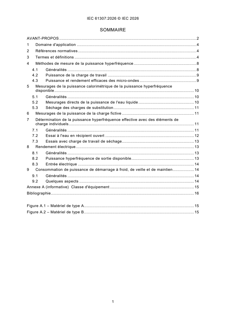
SOMMAIRE
AVANT-PROPOS . 2
1 Domaine d'application . 4
2 Références normatives . 4
3 Termes et définitions . 4
4 Méthodes de mesure de la puissance hyperfréquence . 8
4.1 Généralités . 8
4.2 Puissance de la charge de travail . 9
4.3 Puissance et rendement efficaces des micro-ondes . 9
5 Mesurages de la puissance calorimétrique de la puissance hyperfréquence
disponible . 10
5.1 Généralités . 10
5.2 Mesurages directs de la puissance de l'eau liquide . 10
5.3 Séchage des charges de substitution . 11
6 Mesurages de la puissance de la charge fictive . 11
7 Détermination de la puissance hyperfréquence effective avec des éléments de
charge individuels . 11
7.1 Généralités . 11
7.2 Essai à l'eau en récipient ouvert . 12
7.3 Essais avec charge de travail de séchage . 13
8 Rendement électrique . 13
8.1 Généralités . 13
8.2 Puissance hyperfréquence de sortie disponible . 13
8.3 Entrée électrique . 14
9 Consommation de puissance de démarrage à froid, de veille et de maintien . 14
9.1 Généralités . 14
9.2 Quelques aspects . 14
Annexe A (informative) Classe d'équipement . 15
Bibliographie . 16
Figure A.1 – Matériel de type A . 15
Figure A.2 – Matériel de type B . 15
COMMISSION ÉLECTROTECHNIQUE INTERNATIONALE
____________
Installations industrielles de chauffage par micro-ondes -
Méthodes d'essai pour la détermination de la puissance de sortie
AVANT-PROPOS
1) La Commission Électrotechnique Internationale (IEC) est une organisation mondiale de normalisation composée
de l'ensemble des comités électrotechniques nationaux (Comités nationaux de l'IEC). L'IEC a pour objet de
favoriser la coopération internationale pour toutes les questions de normalisation dans les domaines de
l'électricité et de l'électronique. À cet effet, l'IEC – entre autres activités – publie des Normes internationales,
des Spécifications techniques, des Rapports techniques, des Spécifications accessibles au public (PAS) et des
Guides (ci-après dénommés "Publication(s) de l'IEC"). Leur élaboration est confiée à des comités d'études, aux
travaux desquels tout Comité national intéressé par le sujet traité peut participer. Les organisations
internationales, gouvernementales et non gouvernementales, en liaison avec l'IEC, participent également aux
travaux. L'IEC collabore étroitement avec l'Organisation Internationale de Normalisation (ISO), selon des
conditions fixées par accord entre les deux organisations.
2) Les décisions ou accords officiels de l'IEC concernant les questions techniques représentent, dans la mesure du
possible, un accord international sur les sujets étudiés, étant donné que les Comités nationaux de l'IEC intéressés
sont représentés dans chaque comité d'études.
3) Les Publications de l'IEC se présentent sous la forme de recommandations internationales et sont agréées
comme telles par les Comités nationaux de l'IEC. Tous les efforts raisonnables sont entrepris afin que l'IEC
s'assure de l'exactitude du contenu technique de ses publications; l'IEC ne peut pas être tenue responsable de
l'éventuelle mauvaise utilisation ou interprétation qui en est faite par un quelconque utilisateur final.
4) Dans le but d'encourager l'uniformité internationale, les Comités nationaux de l'IEC s'engagent, dans toute la
mesure possible, à appliquer de façon transparente les Publications de l'IEC dans leurs publications nationales
et régionales. Toutes divergences entre toutes Publications de l'IEC et toutes publications nationales ou
régionales correspondantes doivent être indiquées en termes clairs dans ces dernières.
5) L'IEC elle-même ne fournit aucune attestation de conformité. Des organismes de certification indépendants
fournissent des services d'évaluation de conformité et, dans certains secteurs, accèdent aux marques de
conformité de l'IEC. L'IEC n'est responsable d'aucun des services effectués par les organismes de certification
indépendants.
6) Tous les utilisateurs doivent s'assurer qu'ils sont en possession de la dernière édition de cette publication.
7) Aucune responsabilité ne doit être imputée à l'IEC, à ses administrateurs, employés, auxiliaires ou mandataires,
y compris ses experts particuliers et les membres de ses comités d'études et des Comités nationaux de l'IEC,
pour tout préjudice causé en cas de dommages corporels et matériels, ou de tout autre dommage de quelque
nature que ce soit, directe ou indirecte, ou pour supporter les coûts (y compris les frais de justice) et les dépenses
découlant de la publication ou de l'utilisation de cette Publication de l'IEC ou de toute autre Publication de l'IEC,
ou au crédit qui lui est accordé.
8) L'attention est attirée sur les références normatives citées dans cette publication. L'utilisation de publications
référencées est obligatoire pour une application correcte de la présente publication.
9) L'IEC attire l'attention sur le fait que la mise en application du présent document peut entraîner l'utilisation d'un
ou de plusieurs brevets. L'IEC ne prend pas position quant à la preuve, à la validité et à l'applicabilité de tout
droit de brevet revendiqué à cet égard. À la date de publication du présent document, l'IEC n'a pas reçu
notification qu'un ou plusieurs brevets pouvaient être nécessaires à sa mise en application. Toutefois, il y a lieu
d'avertir les responsables de la mise en application du présent document que des informations plus récentes
sont susceptibles de figurer dans la base de données de brevets, disponible à l'adresse https://patents.iec.ch.
L'IEC ne saurait être tenue pour responsable de ne pas avoir identifié de tels droits de brevets.
L'IEC 61307 a été établie par le comité d'études 27 de l'IEC: Chauffage électrique industriel et
traitement électromagnétique. Il s'agit d'une Norme internationale.
Cette quatrième édition annule et remplace la troisième édition parue en 2011. Cette édition
constitue une révision technique.
Cette édition inclut les modifications techniques significatives suivantes par rapport à l'édition
précédente:
a) elle couvre non seulement les modes veille et veille, mais également la consommation de
puissance de démarrage, veille et maintien, ainsi que d'autres aspects de la flexibilité de
fonctionnement;
b) des descriptions plus détaillées des aspects de la puissance hyperfréquence et de la
manipulation des types d'équipements A et B.
Le texte de la présente Norme internationale est issu des documents suivants:
Projet Rapport de vote
27/1243/FDIS 27/1247/RVD
Le rapport de vote indiqué dans le tableau ci-dessus donne toute information sur le vote ayant
abouti à son approbation.
La langue utilisée pour l'élaboration de la présente Norme internationale est l'anglais.
Le présent document a été rédigé conformément aux directives ISO/IEC, Partie 2, et élaboré
conformément aux directives ISO/IEC, Partie 1 et aux directives ISO/IEC, Supplément IEC,
disponibles à l’adresse www.iec.ch/members_experts/refdocs. Les principaux types de
documents développés par l'IEC sont décrits plus en détail à l'adresse www.iec.ch/publications.
Le comité a décidé que le contenu de ce document ne sera pas modifié avant la date de stabilité
indiquée sur le site web de l’IEC sous webstore.iec.ch dans les données relatives au document
spécifique. À cette date, le document sera
– reconduit,
– supprimé, ou
– révisé.
1 Domaine d'application
Le présent document spécifie des méthodes d'essai pour la détermination du rendement de
conversion de fréquence à partir de l'entrée électrique, et de la puissance de sortie
hyperfréquence disponible et de la charge de travail dans les installations industrielles de
chauffage à hyperfréquences, ainsi que de la flexibilité opérationnelle.
Le présent document est en principe applicable aux équipements et installations industriels de
chauffage par micro-ondes dans la gamme de fréquences de 300 MHz à 300 GHz, mais il est
axé sur les fréquences ISM à micro-ondes inférieures à 6 GHz.
Le présent document concerne les équipements industriels de chauffage par micro-ondes
fonctionnant comme prévu par les spécifications du fabricant pour un fonctionnement normal.
Le présent document ne s'applique pas aux appareils à usage domestique et analogue
(couverts par l'IEC 60335-2-25 [1] ), usage commercial (couvert par l'IEC 60335-2-90 [2] et
l'IEC 60335-2-110 [3]) ou usage en laboratoire (couvert par l'IEC 61010-2-010 [4]).
2 Références normatives
Les documents suivants sont cités dans le texte de telle sorte qu'ils constituent, pour tout ou
partie de leur contenu, des exigences du présent document. Pour les références datées, seule
l'édition citée s'applique. Pour les références non datées, la dernière édition du document de
référence s'applique (y compris les éventuels amendements).
IEC 60050-841, Vocabulaire Electrotechnique International (VEI) - Partie 841: Électrothermie
industrielle
IEC 60519-6, Sécurité dans les installations destinées au traitement électrothermique et
électromagnétique - Partie 6: Exigences particulières pour les équipements de chauffage et de
traitement diélectriques et à micro-ondes à haute fréquence et à hyperfréquences
3 Termes et définitions
Pour les besoins du présent document, les termes et définitions donnés dans l'IEC 60519-6,
l'IEC 60050-841 ainsi que les suivants s'appliquent.
L'ISO et l'IEC tiennent à jour des bases de données terminologiques destinées à être utilisées
en normalisation aux adresses suivantes:
– IEC Electropedia: disponible à l'adresse https://www.electropedia.org/
– ISO Online browsing platform: disponible à l'adresse https://www.iso.org/obp
3.1
équipement de chauffage à micro-ondes
ensemble de dispositifs électriques et mécaniques destinés au transfert d'énergie
hyperfréquence vers la charge de travail et comprenant, en général, des alimentations, des
générateurs d'hyperfréquences ou des ensembles de générateurs d'hyperfréquences avec des
dispositifs de refroidissement et des circulateurs, le cas échéant, des applicateurs
d'hyperfréquences ou des cavités avec des dispositifs de ventilation, le cas échéant, des câbles
d'interconnexion et des guides d'ondes, des circuits de commande et des moyens de transport
de la charge de travail, le cas échéant
___________
Les chiffres entre crochets renvoient à la Bibliographie.
3.2
classe d'équipement
groupe au sein d'un type d'équipement, utilisant le même principe pour le traitement de la
charge de travail de type A ou B
VOIR l'Annexe A.
Note 1 à l'article Un exemple de type est le matériel à micro-ondes, et un exemple de classe est un tel matériel pour
le chauffage par séchage du bois dans un intervalle de capacité spécifié en utilisant la fréquence ISM 2,45 GHz.
3.3
équipement de type A
<équipement à micro-ondes> avec le générateur de micro-ondes (partie convertisseur de fréquence)
indépendant de, ou séparable de, l'applicateur auquel la puissance micro-ondes est fournie
EXEMPLE Un dispositif d'alimentation coaxial, une jonction à guide d'ondes.
Note 1 à l'article: Ceci permet l'intégration d'un circulateur comme protection pour le magnétron contre la puissance
micro-ondes réfléchie ainsi que d'un syntoniseur pour réduire au minimum la réflexion micro-ondes pour un
accord/une adaptation correct.
Note 2 à l'article: Tous les composants auxiliaires du générateur d'hyperfréquences, tels que les transformateurs de
l'appareil de chauffage cathodique et le système de refroidissement du générateur, sont également séparables.
3.4
équipement de type B
<équipement hyperfréquence> avec le générateur hyperfréquence (partie convertisseur de
fréquence) directement couplé à l'applicateur, sans ligne de transmission entre les deux
3.5
rendement de conversion électrique des appareils de chauffage à micro-ondes
quotient entre la puissance hyperfréquence de sortie disponible et l'entrée électrique de
l'alimentation électrique à fréquence secteur ou de l'ensemble générateur d'hyperfréquences,
aux réglages de puissance pour le fonctionnement prévu
3.6
rendement global
efficacité du système complet, y compris toute la consommation d'énergie auxiliaire, sauf pour
le transport de la charge de travail
EXEMPLE Ventilateurs ou pompes de refroidissement et autres systèmes de refroidissement.
3.7
générateur de micro-ondes
source utilisée pour produire de l'énergie électromagnétique dans la gamme de fréquences de
300 MHz à 300 GHz
Note 1 à l'article: Dans le contexte du présent document, le générateur d'hyperfréquences est uniquement le
composant dans lequel la conversion de fréquence a lieu.
3.8
ensemble générateur de micro-ondes
partie de l'équipement de chauffage par micro-ondes comprenant un appareil produisant de
l'énergie à micro-ondes et son port de sortie de ligne de transmission associé
Note 1 à l'article: L'ensemble comprend le générateur d'hyperfréquences, l'alimentation du générateur
d'hyperfréquences et ses circuits auxiliaires et de commande. Si un circulateur est utilisé, il est également inclus.
Note 2 à l'article: Les appareils de chauffage par micro-ondes contenant un générateur de micro-ondes ont été
classés comme de type A dans les éditions antérieures de l'IEC 61307; les appareils pour lesquels aucun accès de
sortie de ligne de transmission n'est disponible ont été classés comme de type B.
3.9
applicateur à micro-ondes
structure qui applique l'énergie hyperfréquence à la charge
3.10
cavité hyperfréquence
espace fermé par des murs métalliques intérieurs et une porte ou une ouverture d'accès et
dans lequel la charge micro-ondes est placée
3.11
enveloppe pour micro-ondes
structure destinée à confiner l'énergie hyperfréquence dans une région définie
EXEMPLE Une cavité, des joints de porte et des guides d'ondes.
3.12
charge de travail des micro-ondes
objet à traiter par micro-ondes
Note 1 à l'article: La charge de travail comprend tout conteneur, support ou autre dispositif nécessaire au traitement
et qui est directement ou indirectement soumis à la puissance de sortie. L'objet/le matériau traité en tant que tel est
également appelé charge.
3.13
charge normale
charge de travail nominale des micro-ondes à pleine puissance de sortie assignée des
micro-ondes, telle que spécifiée dans la documentation du fabricant
3.14
fonctionnement normal
fonctionnement de l'équipement dans des conditions de charge normale dans des conditions
ambiantes nominales, y compris le réseau d'alimentation électrique nominal
3.15
fonctionnement prévu
plage de sortie hyperfréquence et conditions d'entrée électrique admissibles, pour les charges
de travail prévues telles que spécifiées par le fabricant
Note 1 à l'article: Plusieurs combinaisons de réglages sont généralement spécifiées.
3.16
performance
degré auquel les fonctions prévues, y compris la
consommation d’énergie ou d’énergie et la sortie ainsi que le résultat du traitement de la charge
de travail, sont accomplies
3.17
capacité de l'équipement
mesure de la capacité de cadence de production de l'équipement en fonctionnement normal
prévu
EXEMPLE Débit, masse ou volume.
Note 1 à l'article: La capacité de l'équipement ne fait pas référence au volume de la cavité disponible.
3.18
démarrage à froid
processus par lequel l'équipement est mis sous tension en fonctionnement de veille à chaud à
partir de l'état froid, y compris toutes les autres opérations de démarrage qui permettent à
l'équipement de fonctionner dans les conditions de fonctionnement prévues
Note 1 à l'article: Ce mode de fonctionnement s'applique aux cas où il y a une consommation d'énergie significative
nécessaire pour obtenir un état de l'équipement permettant le traitement réel de la charge de travail.
3.19
pouvoir de maintien
consommation de puissance électrique pendant laquelle la charge de travail est maintenue
dans la chambre de traitement à une température spécifiée
Note 1 à l'article: La température est généralement maintenue pendant une période de temps, destinée à égaliser la
température de la charge de travail.
Note 2 à l'article: Ce mode de fonctionnement n'est pas applicable à certains types d'appareils électrothermiques.
3.20
fonctionnement en veille
mode de fonctionnement en veille
condition de puissance de sortie nulle entre des périodes de fonctionnement continu prévu avec
une puissance de sortie
Note 1 à l'article: Ce mode de fonctionnement permet le démarrage immédiat du fonctionnement à pleine puissance.
Note 2 à l'article: Si le traitement de la charge de travail nécessite des conditions non ambiantes telles qu'une
température élevée, ceci est maintenu par des moyens non hyperfréquences.
Note 3 à l'article: «immédiat» désigne une période de temps compatible avec le chargement, le déchargement ou le
remplacement normal de la charge de travail.
3.21
fonctionnement en veille à chaud
mode de fonctionnement de l'installation se produisant immédiatement après un
fonctionnement normal
EXEMPLE Équipement de type A avec protection du circulateur.
Note 1 à l'article: Ce mode de fonctionnement de l'équipement est avec son état chaud restant, sans charge de
travail, et avec les moyens de fonctionnement prêts pour un fonctionnement normal rapide.
3.22
mesurages calorimétriques
méthode de mesure de la puissance qui utilise l'échauffement dans un milieu comme moyen de
mesure de la puissance absorbée
Note 1 à l'article: Un type différent de mesurages calorimétriques utilise l'enthalpie d'évaporation de l'eau.
Note 2 à l'article: Le milieu, généralement l'eau, est soit l'agent absorbant la puissance, soit la chaleur qui lui est
transférée par un élément absorbant la puissance.
3.23
circulateur
dispositif passif ayant trois ports ou plus dans lequel la puissance entrant dans un port
quelconque est transmise au port suivant selon un ordre donné de séquence
Note 1 à l'article: Lorsqu'une charge absorbante est installée sur l'accès de puissance réfléchie du circulateur, le
magnétron est protégé contre la puissance hyperfréquence réfléchie.
3.24
perte d'insertion
perte résultant de l'insertion d'un réseau dans un système de transmission, rapport de la
puissance délivrée à cette partie du système qui suit le réseau, avant l'insertion du réseau, à
la puissance délivrée à cette même partie après l'insertion du réseau
Note 1 à l'article: La perte d'insertion est généralement expri
...
IEC 61307 ®
Edition 4.0 2026-08
INTERNATIONAL
STANDARD
Industrial microwave heating installations - Test methods for the determination
of power output
ICS 25.180.10 ISBN 978-2-8327-1429-4
All rights reserved. Unless otherwise specified, no part of this publication may be reproduced or utilized in any form or
by any means, electronic or mechanical, including photocopying and microfilm, without permission in writing from either
IEC or IEC's member National Committee in the country of the requester. If you have any questions about IEC copyright
or have an enquiry about obtaining additional rights to this publication, please contact the address below or your local
IEC member National Committee for further information.
IEC Secretariat Tel.: +41 22 919 02 11
3, rue de Varembé info@iec.ch
CH-1211 Geneva 20 www.iec.ch
Switzerland
About the IEC
The International Electrotechnical Commission (IEC) is the leading global organization that prepares and publishes
International Standards for all electrical, electronic and related technologies.
About IEC publications
The technical content of IEC publications is kept under constant review by the IEC. Please make sure that you have the
latest edition, a corrigendum or an amendment might have been published.
IEC publications search - IEC Products & Services Portal - products.iec.ch
webstore.iec.ch/advsearchform Discover our powerful search engine and read freely all the
The advanced search enables to find IEC publications by a publications previews, graphical symbols and the glossary.
variety of criteria (reference number, text, technical With a subscription you will always have access to up to date
committee, …). It also gives information on projects, content tailored to your needs.
replaced and withdrawn publications.
Electropedia - www.electropedia.org
The world's leading online dictionary on electrotechnology,
IEC Just Published - webstore.iec.ch/justpublished
Stay up to date on all new IEC publications. Just Published containing more than 22 500 terminological entries in English
details all new publications released. Available online and and French, with equivalent terms in 25 additional languages.
once a month by email. Also known as the International Electrotechnical Vocabulary
(IEV) online.
IEC Customer Service Centre - webstore.iec.ch/csc
If you wish to give us your feedback on this publication or
need further assistance, please contact the Customer
Service Centre: sales@iec.ch.
CONTENTS
FOREWORD . 2
1 Scope . 4
2 Normative references . 4
3 Terms and definitions . 4
4 Methods of microwave power measurements . 8
4.1 General . 8
4.2 Workload power . 8
4.3 Effective microwave power and efficiency . 9
5 Calorimetric power measurements of available microwave power . 9
5.1 General . 9
5.2 Direct liquid water power measurements . 9
5.3 Drying of substitute loads . 10
6 Dummy load power measurements . 10
7 Determination of effective microwave power with individual load items . 11
7.1 General . 11
7.2 Open container water test . 11
7.3 Tests with drying workload . 12
8 Electrical efficiency . 12
8.1 General . 12
8.2 Available microwave power output . 12
8.3 Electrical input . 12
9 Cold start, standby and holding power consumption . 13
9.1 General . 13
9.2 Some aspects . 13
Annex A (informative) Equipment class . 14
Bibliography . 15
Figure A.1 – Type A equipment . 14
Figure A.2 – Type B equipment . 14
INTERNATIONAL ELECTROTECHNICAL COMMISSION
____________
Industrial microwave heating installations -
Test methods for the determination of power output
FOREWORD
1) The International Electrotechnical Commission (IEC) is a worldwide organization for standardization comprising
all national electrotechnical committees (IEC National Committees). The object of IEC is to promote international
co-operation on all questions concerning standardization in the electrical and electronic fields. To this end and
in addition to other activities, IEC publishes International Standards, Technical Specifications, Technical Reports,
Publicly Available Specifications (PAS) and Guides (hereafter referred to as "IEC Publication(s)"). Their
preparation is entrusted to technical committees; any IEC National Committee interested in the subject dealt with
may participate in this preparatory work. International, governmental and non-governmental organizations liaising
with the IEC also participate in this preparation. IEC collaborates closely with the International Organization for
Standardization (ISO) in accordance with conditions determined by agreement between the two organizations.
2) The formal decisions or agreements of IEC on technical matters express, as nearly as possible, an international
consensus of opinion on the relevant subjects since each technical committee has representation from all
interested IEC National Committees.
3) IEC Publications have the form of recommendations for international use and are accepted by IEC National
Committees in that sense. While all reasonable efforts are made to ensure that the technical content of IEC
Publications is accurate, IEC cannot be held responsible for the way in which they are used or for any
misinterpretation by any end user.
4) In order to promote international uniformity, IEC National Committees undertake to apply IEC Publications
transparently to the maximum extent possible in their national and regional publications. Any divergence between
any IEC Publication and the corresponding national or regional publication shall be clearly indicated in the latter.
5) IEC itself does not provide any attestation of conformity. Independent certification bodies provide conformity
assessment services and, in some areas, access to IEC marks of conformity. IEC is not responsible for any
services carried out by independent certification bodies.
6) All users should ensure that they have the latest edition of this publication.
7) No liability shall attach to IEC or its directors, employees, servants or agents including individual experts and
members of its technical committees and IEC National Committees for any personal injury, property damage or
other damage of any nature whatsoever, whether direct or indirect, or for costs (including legal fees) and
expenses arising out of the publication, use of, or reliance upon, this IEC Publication or any other IEC
Publications.
8) Attention is drawn to the Normative references cited in this publication. Use of the referenced publications is
indispensable for the correct application of this publication.
9) IEC draws attention to the possibility that the implementation of this document may involve the use of (a)
patent(s). IEC takes no position concerning the evidence, validity or applicability of any claimed patent rights in
respect thereof. As of the date of publication of this document, IEC had not received notice of (a) patent(s), which
may be required to implement this document. However, implementers are cautioned that this may not represent
the latest information, which may be obtained from the patent database available at https://patents.iec.ch. IEC
shall not be held responsible for identifying any or all such patent rights.
IEC 61307 has been prepared by IEC technical committee 27: Industrial electroheating and
electromagnetic processing. It is an International Standard.
This fourth edition cancels and replaces the third edition published in 2011. This edition
constitutes a technical revision.
This edition includes the following significant technical changes with respect to the previous
edition:
a) it covers not only the standby and hibernation modes, but also start-up, standby and holding
power consumption, as well as other aspects of operation flexibility;
b) more detailed descriptions of the aspects of microwave power, and handling of the A and B
types of equipment.
The text of this International Standard is based on the following documents:
Draft Report on voting
27/1243/FDIS 27/1247/RVD
Full information on the voting for its approval can be found in the report on voting indicated in
the above table.
The language used for the development of this International Standard is English.
This document was drafted in accordance with ISO/IEC Directives, Part 2, and developed in
accordance with ISO/IEC Directives, Part 1 and ISO/IEC Directives, IEC Supplement, available
at www.iec.ch/members_experts/refdocs. The main document types developed by IEC are
described in greater detail at www.iec.ch/publications.
The committee has decided that the contents of this document will remain unchanged until the
stability date indicated on the IEC website under webstore.iec.ch in the data related to the
specific document. At this date, the document will be
– reconfirmed,
– withdrawn, or
– revised.
1 Scope
This document specifies test methods for the determination of the efficiency of frequency
conversion from the electrical input, and of the available and workload microwave output power
in industrial microwave heating installations, as well as operational flexibility.
This document is in principle applicable to industrial microwave heating equipment and
installations in the frequency range from 300 MHz to 300 GHz but focussed on the microwave
ISM frequencies below 6 GHz.
This document relates to industrial microwave heating equipment operating as intended by the
manufacturer's specifications for normal operation.
This document does not apply to appliances for household and similar use (covered by
IEC 60335-2-25 [1] ), commercial use (covered by IEC 60335-2-90 [2] and IEC 60335-2-110 [3])
or laboratory use (covered by IEC 61010-2-010 [4]).
2 Normative references
The following documents are referred to in the text in such a way that some or all of their content
constitutes requirements of this document. For dated references, only the edition cited applies.
For undated references, the latest edition of the referenced document (including any
amendments) applies.
IEC 60050-841, International Electrotechnical Vocabulary (IEV) - Part 841: Industrial
electroheat
IEC 60519-6, Safety in installations for electroheating and electromagnetic processing - Part 6:
Particular requirements for high frequency dielectric and microwave heating and processing
equipment
3 Terms and definitions
For the purposes of this document, the terms and definitions given in IEC 60519-6,
IEC 60050-841 and the following apply.
ISO and IEC maintain terminology databases for use in standardization at the following
addresses:
– IEC Electropedia: available at https://www.electropedia.org/
– ISO Online browsing platform: available at https://www.iso.org/obp
3.1
microwave heating equipment
assembly of electrical and mechanical devices intended for the transfer of microwave energy to
the workload and comprising, in general, power supplies, microwave generators or microwave
generator assemblies with cooling arrangements and circulators if used, microwave applicators
or cavities with ventilation arrangements if used, interconnecting cables and waveguides,
control circuitry, and means for transporting the workload if used
___________
Numbers in square brackets refer to the Bibliography.
3.2
equipment class
group within a type of equipment, using the same principle for processing of the workload either
type A or type B
SEE: Annex A.
Note 1 to entry: An example of type is microwave equipment, and a class example is such equipment for wood
drying heating in a specified capacity interval using the ISM frequency 2,45 GHz.
3.3
type A equipment
equipment with the microwave generator (frequency converter part) independent
of, or separable from, the applicator to which the microwave power is provided
EXAMPLE A coaxial feeder, a waveguide junction.
Note 1 to entry: This allows the integration of a circulator as protection for the magnetron against reflected
microwave power as well as a tuner to minimize microwave reflection for proper tuning/matching.
Note 2 to entry: Any ancillary microwave generator components such as cathode heater transformers and the
generator cooling system are also separable.
3.4
type B equipment
equipment with the microwave generator (frequency converter part) being directly
coupled to the applicator, without a transmission line in between
3.5
electrical conversion efficiency of microwave heating equipment
quotient between the available microwave power output and the electrical input to the mains
frequency power supply or microwave generator assembly, at power settings for intended
operation
3.6
overall efficiency
efficiency of the complete system including all ancillary power consumption except for workload
transport
EXAMPLE Cooling fans or pumps and other cooling systems.
3.7
microwave generator
source used to produce electromagnetic energy in the frequency range from 300 MHz to
300 GHz
Note 1 to entry: In the context of this document, the microwave generator is only the component where the
frequency conversion takes place.
3.8
microwave generator assembly
part of the microwave heating equipment comprising an apparatus producing microwave energy
and its associated transmission line output port
Note 1 to entry: The assembly includes the microwave generator, the power supply of the microwave generator and
its ancillary and control circuits. If a circulator is used, it is also included.
Note 2 to entry: Microwave heating equipment containing a microwave generator assembly was classified as type
A in earlier editions of IEC 61307; equipment where a transmission line output port is not available was classified as
type B.
3.9
microwave applicator
structure which applies the microwave energy to the load
3.10
microwave cavity
space enclosed by inner metal walls and a door or an access opening and in which the
microwave load is placed
3.11
microwave enclosure
structure which is intended to confine the microwave energy to a defined region
EXAMPLE A cavity, door seals and waveguides.
3.12
microwave workload
object to be treated by microwaves
Note 1 to entry: The workload includes any container, holder or other device necessary for the processing and
which is directly or indirectly subjected to the output power. The processed object/material as such is also called the
load.
3.13
normal load
nominal microwave workload at full rated microwave output power as specified by the
manufacturer's documentation
3.14
normal operation
equipment operation under normal load conditions under nominal ambient conditions including
the nominal electrical supply network
3.15
intended operation
range of microwave output and allowable electrical input conditions, for intended workloads as
specified by the manufacturer
Note 1 to entry: Several setting combinations are typically specified.
3.16
performance
degree to which the intended functions, including energy or
power consumption and output as well as the result of the treatment of the workload are
accomplished
3.17
equipment capacity
measure of the production rate capability of equipment when in intended normal operation
EXAMPLE Flow, mass or volume.
Note 1 to entry: The equipment capacity does not refer to the volume of the available cavity space.
3.18
cold start-up
process by which the equipment is energised into hot standby operation from the cold state,
including all other start-up operations which enable the equipment to run under intended
operation
Note 1 to entry: This mode of operation applies to cases where there is a significant energy consumption needed
for obtaining a state of the equipment allowing the actual processing of the workload.
3.19
holding power
electric power consumption during which the workload is kept in the treatment chamber at a
specified temperature
Note 1 to entry: The temperature is typically maintained for a period of time, intended to equalize the workload
temperature.
Note 2 to entry: This mode of operation is not applicable for certain types of electroheating equipment.
3.20
standby operation
standby mode of operation
condition of zero output power between periods of continuous intended power operation with
power output
Note 1 to entry: This mode of operation allows immediate start of full power operation.
Note 2 to entry: If the treatment of the workload requires non-ambient conditions such as elevated temperature,
this is maintained by non-microwave means.
Note 3 to entry: "immediate" means a time period consistent with normal loading, unloading or replacement of the
workload.
3.21
hot standby operation
mode of operation of the installation occurring immediately after normal operation
EXAMPLE Type A equipment with circulator protection.
Note 1 to entry: This mode of operation of the equipment is with its hot state remaining, without workload, and with
the means of operation ready for prompt normal operation.
3.22
calorimetric measurements
method of measurement of power which uses the temperature rise in a medium as a means of
measuring absorbed power
Note 1 to entry: A different kind of calorimetric measurements uses the enthalpy of evaporation of water.
Note 2 to entry: The medium, typically water, is either the power-absorbing agent or has heat transferred to it from
a power-absorbing element.
3.23
circulator
passive device having three or more ports in which the power entering any port is transmitted
to the next port according to a given order of sequence
Note 1 to
...