


ASTM F504-05(2017)
(Test Method)Standard Test Method for Measuring the Quasi-Static Release Moments of Alpine Ski Bindings
Standard Test Method for Measuring the Quasi-Static Release Moments of Alpine Ski Bindings
SIGNIFICANCE AND USE
5.1 This test method involves simulation in the laboratory of potential injury-producing loads that can occur in skiing, without implying the frequency or the magnitude of the danger. This test method does not include the simulation of all or part of a skier, and care must be taken not to confuse the values of moments measured by the test shaft with the loads subjected to the tibia of a skier under the same conditions.
SCOPE
1.1 This test method covers a procedure for the measurement of release moments of ski bindings under conditions where inertia loadings of the ski binding system are not significant.
1.2 This standard does not purport to address all of the safety concerns, if any, associated with its use. It is the responsibility of the user of this standard to establish appropriate safety and health practices and determine the applicability of regulatory limitations prior to use.
General Information
Buy Standard
Standards Content (Sample)
NOTICE: This standard has either been superseded and replaced by a new version or withdrawn.
Contact ASTM International (www.astm.org) for the latest information
Designation: F504 − 05 (Reapproved 2017)
Standard Test Method for
Measuring the Quasi-Static Release Moments of Alpine Ski
Bindings
ThisstandardisissuedunderthefixeddesignationF504;thenumberimmediatelyfollowingthedesignationindicatestheyearoforiginal
adoptionor,inthecaseofrevision,theyearoflastrevision.Anumberinparenthesesindicatestheyearoflastreapproval.Asuperscript
epsilon (´) indicates an editorial change since the last revision or reapproval.
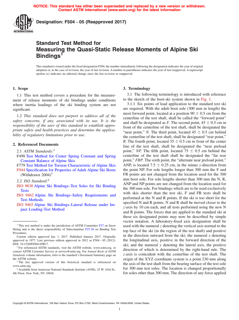
1. Scope 3. Terminology
3.1 The following terminology is introduced with reference
1.1 This test method covers a procedure for the measure-
to the sketch of the boot-ski system shown in Fig. 1.
ment of release moments of ski bindings under conditions
3.1.1 Six points of load application to the standard test ski
where inertia loadings of the ski binding system are not
are required. With the adult boot sole (300 mm in length) the
significant.
mostforwardpoint,locatedataposition90 60.5cmfromthe
1.2 This standard does not purport to address all of the
centerline of the test shaft, shall be called the “forward point”
safety concerns, if any, associated with its use. It is the
andshallbedesignatedas F.Thesecondpoint,45 60.5cmin
responsibility of the user of this standard to establish appro-
front of the centerline of the test shaft, shall be designated the
priate safety and health practices and determine the applica-
“near point,” N. The third point, located 45 6 0.5 cm behind
bility of regulatory limitations prior to use.
thecenterlineofthetestshaft,shallbedesignated“rearpoint,”
R. The fourth point, located 35 6 0.5 cm in front of the center
2. Referenced Documents
line of the test shaft, shall be designated the “near preload
point,” NP. The fifth point, located 75 6 0.5 cm behind the
2.1 ASTM Standards:
centerline of the test shaft shall be designated the “far rear
F498Test Method for Center Spring Constant and Spring
point,” FRP.Thesixthpoint,the“alternatenearpreloadpoint,”
Constant Balance of Alpine Skis
ANP, is located 7.5 6 0.25 cm, in the minus y-direction from
F779Test Method for Torsion Characteristic of Alpine Skis
the point NP. For sole lengths longer than 300 mm the F and
F944Specification for Properties ofAdultAlpine Ski Boots
FR points are not changed from the location used for the 300
(Withdrawn 2004)
mm boot sole. For sole lengths shorter than 300 mm the N, R,
2.2 ISO Standard:
ANPand NPpoints are not changed from the location used for
ISO 9838Alpine Ski Bindings–Test Soles for Ski Binding
the300mmsole.Forbindingswhicharetobeusedexclusively
Tests
with skis shorter than the test ski, F and FR tests shall be
ISO 9462Alpine Ski Bindings–Safety Requirements and
performed at the N and R points. If the ski is too short for the
Test Methods
specifiedNandRpoints,NandRshallbemovedclosertothe
ISO 9465Alpine Ski Bindings–Lateral Release under Im-
z-axis by 10 cm each, and all tests performed using the new N
pact Loading-Test Method
and R points. The forces that are applied to the standard ski at
these six designated points may now be described by simple
vector notation. A laboratory-fixed axis designation shall be
This test method is under the jurisdiction of ASTM Committee F27 on Snow
usedwiththenumeral zdenotingtheverticalaxisnormaltothe
Skiing and is the direct responsibility of Subcommittee F27.10 on Binding Test
top face of the ski (in the region of the test shaft) and positive
Procedures.
in the direction outward from the ski; the numeral x denoting
Current edition approved Jan. 1, 2017. Published January 2017. Originally
approved in 1977. Last previous edition approved in 2012 as F504–05 (2012). the longitudinal axis, positive in the forward direction of the
DOI: 10.1520/F0504-05R17.
ski; and the numeral y denoting the lateral axis, the positive
For referenced ASTM standards, visit the ASTM website, www.astm.org, or
direction of which is determined by the right-hand rule. The
contact ASTM Customer Service at service@astm.org. For Annual Book of ASTM
z-axis is coincident with the centerline of the test shaft. The
Standards volume information, refer to the standard’s Document Summary page on
the ASTM website.
origin of the XYZ coordinate system is a point 230 mm along
The last approved version of this historical standard is referenced on
theaxisofthetestshaftfromthebearingsurfaceofthetestsole
www.astm.org.
4 for 300 mm test soles. The location is changed proportionally
Available fromAmerican National Standards Institute (ANSI), 25 W. 43rd St.,
4th Floor, New York, NY 10036. forsolesotherthan300mm.Thedirectionofanyforceapplied
Copyright © ASTM International, 100 Barr Harbor Drive, PO Box C700, West Conshohocken, PA 19428-2959. United States
F504 − 05 (2017)
momentsmeasuredbythetestshaftwiththeloadssubjectedto
the tibia of a skier under the same conditions.
6. Apparatus
6.1 Ski:
6.1.1 Ski—Three test skis are defined in Table 1 of ISO
9462. The mounting platform shall be as specified in the
relevant ASTM standard. The boot’s ski location marker as
shownonSpecificationF944orISO9838shallbealignedwith
thebootcenterlinemarkerontheski.Iftherearenomarkerson
thebootorskithecenterofthebootsoleshallbelocated15 6
0.5cmbehindthecenteroftheski’sprojectedlengthunlessthe
relevant ASTM standard applies.
6.2 Boot—Four test soles are defined in Table 2 of ISO
FIG. 1 Load Application
9462. The standard adult sole shall be 30 6 0.5 cm in length
and shall be adjustable, over a range of 64 cm. It shall be
constructed to meet the requirements of ISO 9838. Details
to the ski is defined by its unit vector. The magnitude of a
concerning boot characteristics shall conform to the relevant
preload force applied to the ski is defined by the M or M
z y
ASTMstandard.However,itshallbepermissibletomodifythe
moment created by the force.
boot if the binding manufacturer specifies that modification is
necessary for proper function of the binding.
4. Summary of Test Method
6.3 Stiffener—When a ski stiffener is called for (see Annex
4.1 The ski binding is mounted on a standard ski and a
A1andAnnexA2),achannelofdimensions75to80mmwide
standardbootsoleisinsertedintothebinding.Arelativelystiff
by35to40mmhighby4to5mmthickshallbeusedtostiffen
test shaft instrumented for moments is affixed to the sole and
the ski between the near and rear points. The channel shall be
attached rigidly to the test frame. The apparatus is shown in
made of 6061 T6 aluminum, or equivalent. The bar shall be
Fig. 2.
attachedtotheskibybolts,screws,orclampsat Nand Rpoints
4.2 Loads sufficient to produce binding release are applied
and at a point half way between N and R points. The stiffener
to the binding by forcing the ski to displace relative to the
described in Fig. A1.1 meets this requirement.
frame until release occurs. The components of the moments
6.4 Test Frame:
transmitted through the binding to the test shaft are recorded.
6.4.1 The test frame consists of all mechanical components
These records are interpreted to provide the static release
that connect the boot to a stationary reference, including the
moments of the binding.
boot sole attachment, the test shaft, and the supporting struc-
ture for the test shaft. The test frame shall include a boot sole
5. Significance and Use
attachment constructed in accordance with ISO 9838 for the
5.1 Thistestmethodinvolvessimulationinthelaboratoryof
standard sole.
potential injury-producing loads that can occur in skiing,
6.4.2 Theanglebetweenthebottomofthebootsoleandthe
withoutimplyingthefrequencyorthemagnitudeofthedanger.
test shaft shall be 90 6 1° in the z−x and z−y planes; the
This test method does not include the simulation of all or part
positionsofcenterlineofthetestshaftrelativetothebootshall
of a skier, and care must be taken not to confuse the values of
be at a longitudinal location 20 6 1 cm from the front of the
boot sole when the 300-mm boot sole is used. For other boot
sole lengths the distance shall be two thirds the distance from
the front of the sole.
6.4.3 The test shaft and associated instrumentation shall be
capable of measuring moments about the x-, y-, and z-axes as
required. Further specifications for the test shaft as part of the
instrumentation system are discussed in 6.6.
6.4.4 The linear compliance of all combined mechanical
−6
components of the test frame shall be no more than 4×10
m/N in either of the x or y directions, and no more than
−7
4×10 m/N in the z direction for loads applied at the
intersection of the test shaft and the attachment plate. The
−5
angular compliance shall be no more than 5×10 rad/N · m
for rotations around the x, y,or z-axes.
NOTE 1—When an associated high-speed test series is established, the
−5
angular compliance shall be no more than 2.5×10 rad/N·mfor
FIG. 2 Test Equipment rotations around the x-, y-, or z-axes.
F504 − 05 (2017)
6.5 Cable:
6.5.1 The minimum length of cable between the point of
attachment to the ski and the nearest support shall be 1 m.
6.5.2 The cable shall be attached to the ski such that the
resultant force transmitted through the cable passes within 1
cm of the centeroid of the cross section of the ski.
6.5.3 Preloads are applied through a pulley near the base of
the load cell pedestal with an attachment swivel not more than
12 cm offset from the load cell axis. A spring with a spring
constant of 65 N/cm (610%) and an unloaded length of at
least 20 cm is attached between the preload cable and the
attachment fixture. When a preload (PL) is used in a test the
preloadcableforcewillinduceamoment M thatisaspecified
y
FIG. 4 Test 1.3
percentage of the nominal release moment in test 2.1 (see Fig.
11).
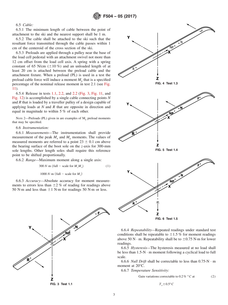
6.5.4 Release in tests 1.1, 2.2, and 2.2 (Fig. 3, Fig. 11, and
Fig. 12) is accomplished by a single cable connecting points N
and Rthatisloadedbyatravellerpulleyofadesigncapableof
applying loads at N and R that are opposite in direction and
equal in magnitude to within 5% of each other.
NOTE 2—Preloads (PL) given in are examples of M preload moments
y
that may be specified.
6.6 Instrumentation:
6.6.1 Measurements—The instrumentation shall provide
measurement of the peak M and M moments. The values of
z y
measured moments are referred to a point 23 6 0.1 cm above
the bearing surface of the boot sole on the z-axis for 300-mm
FIG. 5 Test 1.4
sole lengths. Other length soles shall require this reference
point to be shifted proportionally.
6.6.2 Range—Maximum moment along a single axis:
300 N·m ~full 2scalefor M M ! (1)
z x
1000 N·m full 2scalefor M
~ !
y
6.6.3 Accuracy—Absolute accuracy for moment measure-
ments to errors less than 62% of reading for readings above
50 N·m and less than 61 N·m for readings 50 N·m or less.
FIG. 6 Test 1.5
6.6.4 Repeatability—Repeated readings under standard test
conditions shall be repeatable to 61.5% for moment readings
above50N·m.Repeatabilityshallbeto 60.75N·mforlower
readings.
6.6.5 Hysteresis—The hysteresis measured at no load shall
belessthan1.5-N·mmomentfollowingacyclicalloadtofull
scale.
6.6.6 Null Drift shall be correctable to less than 0.75-N · m
moment at 20°C.
6.6.7 Temperature Sensitivity:
Gainvariations:correctableto0.2% °C at (2)
FIG. 3 Test 1.1 T 60.5°C
o
F504 − 05 (2017)
PL=.75×[2.1]
PL=.75×[2.1]
FIG. 7 Test 1.6
FIG. 10 Test 1.11
PL=.50×[2.1]
FIG. 11 Test 2.1
FIG. 8 Test 1.8
FIG. 12 Test 2.2
PL=.50×[2.1]
FIG. 9 Test 1.10
6.6.8 Frequency Response—Gain measured at full scale
shallvarylessthan1dBoverthebandwidth0to100Hz.Phase
lag shall be less than 10° over the same bandwidth.
Nullvariations:correctableto0.5 N·m/°C at (3)
6.7 Load Application:
T 60.5°C
o
6.7.1 Locations and Directions of Application—The appa-
where: T =equilibrium environmental temperature and is ratus shall have the capability of applying the load configura-
o
in the range from−20 to+20°C. tions in accordance with Figs. 3-15. Tests in Category 1 have
F504 − 05 (2017)
FIG. 13 Test 2.3
FIG. 14 Test 2.5
FIG. 15 Test 2.8
a significant M component; tests in Category 2 have a Figs. 3-15 as measured under a cable tension equivalent to
z
significant M component.Notethattheunitvectorisgivenfor
approximately 10% of the nominal release load in tests 1.1 or
y
all loads applied through the cable system. The unit vector for
2.1 as appropriate.
a release load is shown as a solid line while the unit vector for
6.7.2 Rates of Application—The apparatus shall have the
a preload is shown as a dashed line. Preloads (PL) are given in
ability of applying loads such that the linear speed of the cable
terms of the nominal value of test 2.1 (see Fig. 11).
at the point of attachment to the ski shall be adjustable to two
6.7.1.1 Release load and preload cables shall be adjustable
different rates as follows: 2 6 0.5 cm/s and 60 6 10 cm/s.
to within 2° of the orientation of the unit vector specified in
F504 − 05 (2017)
6.7.3 Calibration—The load cell is calibrated using the 8. Procedure
fixture and procedures defined in Annex A.
8.1 An individual release measurement shall consist of
6.7.4 Zeroing—The instrumentation is zeroed without the
attaching a ski-binding system to the test apparatus and
ski attached to the test sole.
applying a load configuration, as specified in 6.7.1 and 6.7.2,
sufficient to cause the binding mechanism to release while
7. Test Specimen Preparation
simultaneously recording information sufficient to determine
7.1 Bindings should be mounted in accordance with the
the two peak M and M moments. Refer to Annex A2 for
z y
manufacturer’s specifications, and boot surfaces and interfaces
step-by-step procedures.
shall be cleaned with an appropriate cleaner, unless otherwise
specified by environmental test procedures. All tests shall be
9. Keywords
performed with boot-binding contact points wet by a mist of
distilled water unless otherwise specified by environmental 9.1 alpine ski binding; release binding; release envelope;
release moment
procedures.
ANNEXES
(Mandatory Information)
A1. FIXTURES
A1.1 Scope A1.2 Fixtures and Test Configurations
A1.1.1 This Annex describes fixtures that may be used to A1.2.1 Use the ski stiffening fixture described in Fig.A1.1
adapt the device described in Test Method F504 to meet the and release loads as defined in Fig. 3 and Fig. 11 unless
requirements of ISO 9462 Method B. otherwise specified.
FIG. A1.1 Ski Stiffening Fixture
F504 − 05 (2017)
A1.2.2 To perform the release with ski deflection test, use A1.2.5 To perform the release with combined loading test
the fixture described in Fig. A1.2. for influence of backward lean of the body, use the load
configurationdefinedinFig.A1.5toapplythepreloadmoment
A1.2.3
...
This document is not an ASTM standard and is intended only to provide the user of an ASTM standard an indication of what changes have been made to the previous version. Because
it may not be technically possible to adequately depict all changes accurately, ASTM recommends that users consult prior editions as appropriate. In all cases only the current version
of the standard as published by ASTM is to be considered the official document.
Designation: F504 − 05 (Reapproved 2012) F504 − 05 (Reapproved 2017)
Standard Test Method for
Measuring the Quasi-Static Release Moments of Alpine Ski
Bindings
This standard is issued under the fixed designation F504; the number immediately following the designation indicates the year of original
adoption or, in the case of revision, the year of last revision. A number in parentheses indicates the year of last reapproval. A superscript
epsilon (´) indicates an editorial change since the last revision or reapproval.
1. Scope
1.1 This test method covers a procedure for the measurement of release moments of ski bindings under conditions where inertia
loadings of the ski binding system are not significant.
1.2 This standard does not purport to address all of the safety concerns, if any, associated with its use. It is the responsibility
of the user of this standard to establish appropriate safety and health practices and determine the applicability of regulatory
limitations prior to use.
2. Referenced Documents
2.1 ASTM Standards:
F498 Test Method for Center Spring Constant and Spring Constant Balance of Alpine Skis
F779 Test Method for Torsion Characteristic of Alpine Skis
F944 Specification for Properties of Adult Alpine Ski Boots (Withdrawn 2004)
2.2 ISO Standard:
ISO 9838 Alpine Ski Bindings–Test Soles for Ski Binding Tests
ISO 9462 Alpine Ski Bindings–Safety Requirements and Test Methods
ISO 9465 Alpine Ski Bindings–Lateral Release under Impact Loading-Test Method
3. Terminology
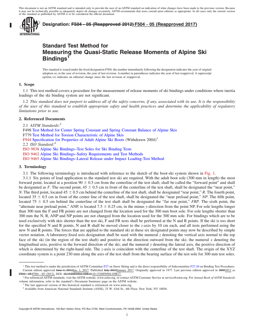
3.1 The following terminology is introduced with reference to the sketch of the boot-ski system shown in Fig. 1.
3.1.1 Six points of load application to the standard test ski are required. With the adult boot sole (300 mm in length) the most
forward point, located at a position 90 6 0.5 cm from the centerline of the test shaft, shall be called the “forward point” and shall
be designated as F. The second point, 45 6 0.5 cm in front of the centerline of the test shaft, shall be designated the “near point,”
N. The third point, located 45 6 0.5 cm behind the centerline of the test shaft, shall be designated “rear point,” R. The fourth point,
located 35 6 0.5 cm in front of the center line of the test shaft, shall be designated the “near preload point,” NP. The fifth point,
located 75 6 0.5 cm behind the centerline of the test shaft shall be designated the “far rear point,” FRP. The sixth point, the
“alternate near preload point,” ANP, is located 7.5 6 0.25 cm, in the minus y-direction from the point NP. For sole lengths longer
than 300 mm the F and FR points are not changed from the location used for the 300 mm boot sole. For sole lengths shorter than
300 mm the N, R, ANP and NP points are not changed from the location used for the 300 mm sole. For bindings which are to be
used exclusively with skis shorter than the test ski, F and FR tests shall be performed at the N and R points. If the ski is too short
for the specified N and R points, N and R shall be moved closer to the z-axis by 10 cm each, and all tests performed using the
new N and R points. The forces that are applied to the standard ski at these six designated points may now be described by simple
vector notation. A laboratory-fixed axis designation shall be used with the numeral z denoting the vertical axis normal to the top
face of the ski (in the region of the test shaft) and positive in the direction outward from the ski; the numeral x denoting the
longitudinal axis, positive in the forward direction of the ski; and the numeral y denoting the lateral axis, the positive direction of
which is determined by the right-hand rule. The z-axis is coincident with the centerline of the test shaft. The origin of the XYZ
coordinate system is a point 230 mm along the axis of the test shaft from the bearing surface of the test sole for 300 mm test soles.
This test method is under the jurisdiction of ASTM Committee F27 on Snow Skiing and is the direct responsibility of Subcommittee F27.10 on Binding Test Procedures.
Current edition approved June 1, 2012Jan. 1, 2017. Published July 2012January 2017. Originally approved in 1977. Last previous edition approved in 20052012 as
F504 – 05.F504 – 05 (2012). DOI: 10.1520/F0504-05R12.10.1520/F0504-05R17.
For referenced ASTM standards, visit the ASTM website, www.astm.org, or contact ASTM Customer Service at service@astm.org. For Annual Book of ASTM Standards
volume information, refer to the standard’s Document Summary page on the ASTM website.
The last approved version of this historical standard is referenced on www.astm.org.
Available from American National Standards Institute (ANSI), 25 W. 43rd St., 4th Floor, New York, NY 10036.
Copyright © ASTM International, 100 Barr Harbor Drive, PO Box C700, West Conshohocken, PA 19428-2959. United States
F504 − 05 (2017)
FIG. 1 Load Application
The location is changed proportionally for soles other than 300 mm. The direction of any force applied to the ski is defined by
its unit vector. The magnitude of a preload force applied to the ski is defined by the M or M moment created by the force.
z y
4. Summary of Test Method
4.1 The ski binding is mounted on a standard ski and a standard boot sole is inserted into the binding. A relatively stiff test shaft
instrumented for moments is affixed to the sole and attached rigidly to the test frame. The apparatus is shown in Fig. 2.
4.2 Loads sufficient to produce binding release are applied to the binding by forcing the ski to displace relative to the frame until
release occurs. The components of the moments transmitted through the binding to the test shaft are recorded. These records are
interpreted to provide the static release moments of the binding.
5. Significance and Use
5.1 This test method involves simulation in the laboratory of potential injury-producing loads that can occur in skiing, without
implying the frequency or the magnitude of the danger. This test method does not include the simulation of all or part of a skier,
and care must be taken not to confuse the values of moments measured by the test shaft with the loads subjected to the tibia of
a skier under the same conditions.
6. Apparatus
6.1 Ski:
6.1.1 Ski—Three test skis are defined in Table 1 of ISO 9462. The mounting platform shall be as specified in the relevant ASTM
standard. The boot’s ski location marker as shown on Specification F944 or ISO 9838 shall be aligned with the boot centerline
marker on the ski. If there are no markers on the boot or ski the center of the boot sole shall be located 15 6 0.5 cm behind the
center of the ski’s projected length unless the relevant ASTM standard applies.
FIG. 2 Test Equipment
F504 − 05 (2017)
6.2 Boot—Four test soles are defined in Table 2 of ISO 9462. The standard adult sole shall be 30 6 0.5 cm in length and shall
be adjustable, over a range of 64 cm. It shall be constructed to meet the requirements of ISO 9838. Details concerning boot
characteristics shall conform to the relevant ASTM standard. However, it shall be permissible to modify the boot if the binding
manufacturer specifies that modification is necessary for proper function of the binding.
6.3 Stiffener—When a ski stiffener is called for (see Annex A1 and Annex A2), a channel of dimensions 75 to 80 mm wide by
35 to 40 mm high by 4 to 5 mm thick shall be used to stiffen the ski between the near and rear points. The channel shall be made
of 6061 T6 aluminum, or equivalent. The bar shall be attached to the ski by bolts, screws, or clamps at N and R points and at a
point half way between N and R points. The stiffener described in Fig. A1.1 meets this requirement.
6.4 Test Frame:
6.4.1 The test frame consists of all mechanical components that connect the boot to a stationary reference, including the boot
sole attachment, the test shaft, and the supporting structure for the test shaft. The test frame shall include a boot sole attachment
constructed in accordance with ISO 9838 for the standard sole.
6.4.2 The angle between the bottom of the boot sole and the test shaft shall be 90 6 1° in the z−x and z−y planes; the positions
of centerline of the test shaft relative to the boot shall be at a longitudinal location 20 6 1 cm from the front of the boot sole when
the 300-mm boot sole is used. For other boot sole lengths the distance shall be two thirds the distance from the front of the sole.
6.4.3 The test shaft and associated instrumentation shall be capable of measuring moments about the x-, y-, and z-axes as
required. Further specifications for the test shaft as part of the instrumentation system are discussed in 6.6.
−6
6.4.4 The linear compliance of all combined mechanical components of the test frame shall be no more than 4 × 10 m/N in
−7
either of the x or y directions, and no more than 4 × 10 m/N in the z direction for loads applied at the intersection of the test shaft
−5
and the attachment plate. The angular compliance shall be no more than 5 × 10 rad/N · m for rotations around the x,y, or z-axes.
−5
NOTE 1—When an associated high-speed test series is established, the angular compliance shall be no more than 2.5 × 10 rad/N · m for rotations
around the x-, y-, or z-axes.
6.5 Cable:
6.5.1 The minimum length of cable between the point of attachment to the ski and the nearest support shall be 1 m.
6.5.2 The cable shall be attached to the ski such that the resultant force transmitted through the cable passes within 1 cm of the
centeroid of the cross section of the ski.
6.5.3 Preloads are applied through a pulley near the base of the load cell pedestal with an attachment swivel not more than 12
cm offset from the load cell axis. A spring with a spring constant of 65 N/cm (610 %) and an unloaded length of at least 20 cm
is attached between the preload cable and the attachment fixture. When a preload (PL) is used in a test the preload cable force will
induce a moment M that is a specified percentage of the nominal release moment in test 2.1 (see Fig. 11).
y
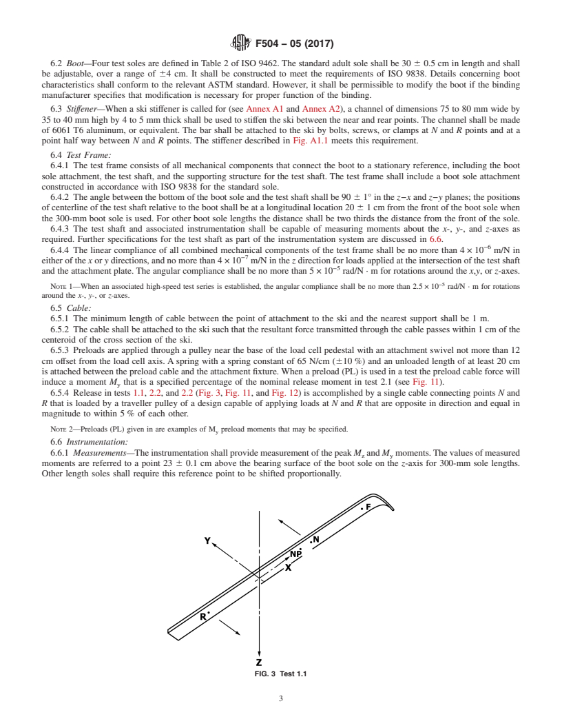
6.5.4 Release in tests 1.1, 2.2, and 2.2 (Fig. 3, Fig. 11, and Fig. 12) is accomplished by a single cable connecting points N and
R that is loaded by a traveller pulley of a design capable of applying loads at N and R that are opposite in direction and equal in
magnitude to within 5 % of each other.
NOTE 2—Preloads (PL) given in are examples of M preload moments that may be specified.
y
6.6 Instrumentation:
6.6.1 Measurements—The instrumentation shall provide measurement of the peak M and M moments. The values of measured
z y
moments are referred to a point 23 6 0.1 cm above the bearing surface of the boot sole on the z-axis for 300-mm sole lengths.
Other length soles shall require this reference point to be shifted proportionally.
FIG. 3 Test 1.1
F504 − 05 (2017)
FIG. 4 Test 1.3
FIG. 5 Test 1.4
FIG. 6 Test 1.5
6.6.2 Range—Maximum moment along a single axis:
300 N·m ~full 2 scale for M M ! (1)
z x
1000 N·m full 2 scale for M
~ !
y
6.6.3 Accuracy—Absolute accuracy for moment measurements to errors less than 62 % of reading for readings above 50 N·m
and less than 61 N·m for readings 50 N·m or less.
6.6.4 Repeatability—Repeated readings under standard test conditions shall be repeatable to 61.5 % for moment readings above
50 N · m. Repeatability shall be to 60.75 N·m for lower readings.
6.6.5 Hysteresis—The hysteresis measured at no load shall be less than 1.5-N · m moment following a cyclical load to full scale.
6.6.6 Null Drift shall be correctable to less than 0.75-N · m moment at 20°C.
6.6.7 Temperature Sensitivity:
F504 − 05 (2017)
PL = .75 × [2.1]
FIG. 7 Test 1.6
PL = .50 × [2.1]
FIG. 8 Test 1.8
PL = .50 × [2.1]
FIG. 9 Test 1.10
Gain variations:correctable to 0.2 % °C at (2)
T 60.5°C
o
Null variations:correctable to 0.5 N·m/°C at (3)
T 60.5°C
o
F504 − 05 (2017)
PL = .75 × [2.1]
FIG. 10 Test 1.11
FIG. 11 Test 2.1
FIG. 12 Test 2.2
where: T = equilibrium environmental temperature and is in the range from −20 to +20°C.
o
6.6.8 Frequency Response—Gain measured at full scale shall vary less than 1 dB over the bandwidth 0 to 100 Hz. Phase lag
shall be less than 10° over the same bandwidth.
6.7 Load Application:
6.7.1 Locations and Directions of Application—The apparatus shall have the capability of applying the load configurations in
accordance with Figs. 3-15. Tests in Category 1 have a significant M component; tests in Category 2 have a significant M
z y
F504 − 05 (2017)
FIG. 13 Test 2.3
FIG. 14 Test 2.5
FIG. 15 Test 2.8
component. Note that the unit vector is given for all loads applied through the cable system. The unit vector for a release load is
shown as a solid line while the unit vector for a preload is shown as a dashed line. Preloads (PL) are given in terms of the nominal
value of test 2.1 (see Fig. 11).
6.7.1.1 Release load and preload cables shall be adjustable to within 2° of the orientation of the unit vector specified in Figs.
3-15 as measured under a cable tension equivalent to approximately 10 % of the nominal release load in tests 1.1 or 2.1 as
appropriate.
6.7.2 Rates of Application—The apparatus shall have the ability of applying loads such that the linear speed of the cable at the
point of attachment to the ski shall be adjustable to two different rates as follows: 2 6 0.5 cm/s and 60 6 10 cm/s.
6.7.3 Calibration—The load cell is calibrated using the fixture and procedures defined in Annex A.
F504 − 05 (2017)
6.7.4 Zeroing—The instrumentation is zeroed without the ski attached to the test sole.
7. Test Specimen Preparation
7.1 Bindings should be mounted in accordance with the manufacturer’s specifications, and boot surfaces and interfaces shall be
cleaned with an appropriate cleaner, unless otherwise specified by environmental test procedures. All tests shall be performed with
boot-binding contact points wet by a mist of distilled water unless otherwise specified by environmental procedures.
8. Procedure
8.1 An individual release measurement shall consist of attaching a ski-binding system to the test apparatus and applying a load
configuration, as specified in 6.7.1 and 6.7.2, sufficient to cause the binding mechanism to release while simultaneously recording
information sufficient to determine the tw
...
Questions, Comments and Discussion
Ask us and Technical Secretary will try to provide an answer. You can facilitate discussion about the standard in here.