


oSIST prEN 1931:2026
(Main)Flexible sheets for waterproofing - Bitumen, plastic and rubber sheets for roof waterproofing - Determination of water vapour transmission properties
General Information
- Abstract
This document specifies a method for the determination of the water vapour transmission properties of waterproofing sheets. It is applicable to factory made bitumen, plastic and rubber sheets for roof waterproofing, damp proof sheets, damp proof courses, underlays and vapour control layers.
- Status
- Not Published
- Public Enquiry End Date
- 29-Oct-2026
- Technical Committee
- VLA - Water proofing
- Current Stage
- 4020 - Public enquire (PE) (Adopted Project)
- Start Date
- 25-Aug-2026
- Due Date
- 12-Jan-2027

Overview
oSIST prEN 1931:2026 is a draft European Standard developed by SIST for the determination of water vapour transmission properties in flexible sheets used for waterproofing. This standard applies to factory-made bitumen, plastic, and rubber sheets primarily used in roof waterproofing, as well as damp proof sheets, damp proof courses, underlays, and vapour control layers. The document establishes a uniform testing method for assessing these products' ability to resist or transmit water vapour, ensuring their suitability for construction and building applications where moisture control is critical.
Key Topics
- Water Vapour Transmission Properties: The core focus is on methods to precisely measure how much water vapour passes through samples of waterproofing sheets under controlled laboratory conditions.
- Applicability: Relevant for a wide array of products, including bitumen sheets, plastic and rubber sheets, underlays, damp proof courses, and vapour control layers.
- Test Methodology: Details test specimen preparation, test chamber conditions (23°C, 75% relative humidity), apparatus requirements (test cups, analytical balances, sensors), and calculation methods for key parameters like water vapour permeance, diffusion-equivalent air layer thickness (sd-value), and resistance factors (µ-value).
- Sampling and Preparation: Specifies minimum sampling requirements and emphasizes representative sampling from production batches to ensure valid results across product variations.
- Result Expression and Reporting: Outlines how to calculate and express results, including compensated mass change, steady-state mass change rate, and performance indices (such as sd and µ values). The standard also prescribes mandatory elements for the test report to ensure transparency and comparability.
Applications
- Roof Waterproofing: Ensuring that bitumen, plastic, or rubber sheets perform reliably as barriers against vapour ingress, thereby protecting building structures from moisture damage.
- Damp Proofing: Applicable to materials that prevent moisture rising from the ground or passing through building elements, helping maintain a healthy indoor environment.
- Vapour Control Layers: Critical for modern building envelopes where moisture regulation is key for insulation performance and structural durability.
- Product Characterization and Quality Control: Manufacturers use the standard to demonstrate compliance, develop new products, and perform routine quality assurance. The standard also supports architects, contractors, and specifiers in material selection based on verifiable performance data.
Related Standards
The following standards are referenced within oSIST prEN 1931:2026 or are commonly used for complementary testing and specification:
- EN 13416:2023 - Rules for sampling flexible sheets for waterproofing.
- EN 1849-1 - Determination of thickness and mass per unit area for bitumen sheets.
- EN 1849-2 - Determination of thickness and mass per unit area for plastic and rubber sheets.
Organizations and practitioners involved in building envelope construction, waterproofing materials manufacturing, and building quality assessment rely on these standards to ensure the effective performance of moisture control layers.
Practical Value
Adhering to oSIST prEN 1931:2026 brings significant advantages:
- Reliable Performance Data: Provides standardized, repeatable test results for assessing water vapour transmission, crucial for warranties and specifications.
- Regulatory Compliance: Supports compliance with European and national regulations concerning building materials and moisture control.
- Market Confidence: Enables producers to demonstrate the technical capability of their products, facilitating acceptance across the EU construction sector.
- Improved Building Durability: Assists designers and builders in selecting appropriate membranes, reducing the risk of condensation, mold, and structural degradation from moisture.
By following this European Standard, stakeholders ensure that waterproofing products deliver the expected level of vapour resistance, thereby protecting building investments and occupant wellbeing.
Relations
- Effective Date
- 24-Jun-2026
- Effective Date
- 14-Aug-2024
Get Certified
Connect with accredited certification bodies for this standard

DIBt (Deutsches Institut für Bautechnik)
German Institute for Building Technology.
DIN CERTCO
DIN Group product certification.

Aboma Certification B.V.
Specialized in construction, metal, and transport sectors.
Sponsored listings
Frequently Asked Questions
oSIST prEN 1931:2026 is a draft published by the Slovenian Institute for Standardization (SIST). Its full title is "Flexible sheets for waterproofing - Bitumen, plastic and rubber sheets for roof waterproofing - Determination of water vapour transmission properties". This standard covers: This document specifies a method for the determination of the water vapour transmission properties of waterproofing sheets. It is applicable to factory made bitumen, plastic and rubber sheets for roof waterproofing, damp proof sheets, damp proof courses, underlays and vapour control layers.
This document specifies a method for the determination of the water vapour transmission properties of waterproofing sheets. It is applicable to factory made bitumen, plastic and rubber sheets for roof waterproofing, damp proof sheets, damp proof courses, underlays and vapour control layers.
oSIST prEN 1931:2026 is classified under the following ICS (International Classification for Standards) categories: 91.060.20 - Roofs; 91.100.50 - Binders. Sealing materials. The ICS classification helps identify the subject area and facilitates finding related standards.
oSIST prEN 1931:2026 has the following relationships with other standards: It is inter standard links to SIST EN 1931:2001/AC:2001, SIST EN 1931:2001. Understanding these relationships helps ensure you are using the most current and applicable version of the standard.
oSIST prEN 1931:2026 is associated with the following European legislation: EU Directives/Regulations: 305/2011; Standardization Mandates: M/102. When a standard is cited in the Official Journal of the European Union, products manufactured in conformity with it benefit from a presumption of conformity with the essential requirements of the corresponding EU directive or regulation.
oSIST prEN 1931:2026 is available in PDF format for immediate download after purchase. The document can be added to your cart and obtained through the secure checkout process. Digital delivery ensures instant access to the complete standard document.
Standards Content (Sample)
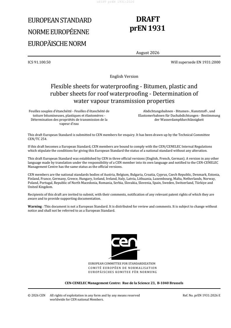
SLOVENSKI STANDARD
01-oktober-2026
Hidroizolacijski trakovi - Bitumenski, polimerni in elastomerni trakovi za tesnjenje
streh - Določanje lastnosti pri prehodu vodne pare
Flexible sheets for waterproofing - Bitumen, plastic and rubber sheets for roof
waterproofing - Determination of water vapour transmission properties
Abdichtungsbahnen - Bitumen-, Kunststoff-, und Elastomerbahnen für
Dachabdichtungen - Bestimmung der Wasserdampfdurchlässigkeit
Feuilles souples d'étanchéité - Feuilles d'étanchéité de toiture bitumineuses, plastiques
et élastomères - Détermination des propriétés de transmission de la vapeur d'eau
Ta slovenski standard je istoveten z: prEN 1931
ICS:
91.060.20 Strehe Roofs
91.100.50 Veziva. Tesnilni materiali Binders. Sealing materials
2003-01.Slovenski inštitut za standardizacijo. Razmnoževanje celote ali delov tega standarda ni dovoljeno.
DRAFT
EUROPEAN STANDARD
NORME EUROPÉENNE
EUROPÄISCHE NORM
August 2026
ICS 91.100.50 Will supersede EN 1931:2000
English Version
Flexible sheets for waterproofing - Bitumen, plastic and
rubber sheets for roof waterproofing - Determination of
water vapour transmission properties
Feuilles souples d'étanchéité - Feuilles d'étanchéité de Abdichtungsbahnen - Bitumen-, Kunststoff-, und
toiture bitumineuses, plastiques et élastomères - Elastomerbahnen für Dachabdichtungen - Bestimmung
Détermination des propriétés de transmission de la der Wasserdampfdurchlässigkeit
vapeur d'eau
This draft European Standard is submitted to CEN members for enquiry. It has been drawn up by the Technical Committee
CEN/TC 254.
If this draft becomes a European Standard, CEN members are bound to comply with the CEN/CENELEC Internal Regulations
which stipulate the conditions for giving this European Standard the status of a national standard without any alteration.
This draft European Standard was established by CEN in three official versions (English, French, German). A version in any other
language made by translation under the responsibility of a CEN member into its own language and notified to the CEN-CENELEC
Management Centre has the same status as the official versions.
CEN members are the national standards bodies of Austria, Belgium, Bulgaria, Croatia, Cyprus, Czech Republic, Denmark, Estonia,
Finland, France, Germany, Greece, Hungary, Iceland, Ireland, Italy, Latvia, Lithuania, Luxembourg, Malta, Netherlands, Norway,
Poland, Portugal, Republic of North Macedonia, Romania, Serbia, Slovakia, Slovenia, Spain, Sweden, Switzerland, Türkiye and
United Kingdom.
Recipients of this draft are invited to submit, with their comments, notification of any relevant patent rights of which they are
aware and to provide supporting documentation.
Warning : This document is not a European Standard. It is distributed for review and comments. It is subject to change without
notice and shall not be referred to as a European Standard.
EUROPEAN COMMITTEE FOR STANDARDIZATION
COMITÉ EUROPÉEN DE NORMALISATION
EUROPÄISCHES KOMITEE FÜR NORMUNG
CEN-CENELEC Management Centre: Rue de la Science 23, B-1040 Brussels
© 2026 CEN All rights of exploitation in any form and by any means reserved Ref. No. prEN 1931:2026 E
worldwide for CEN national Members.
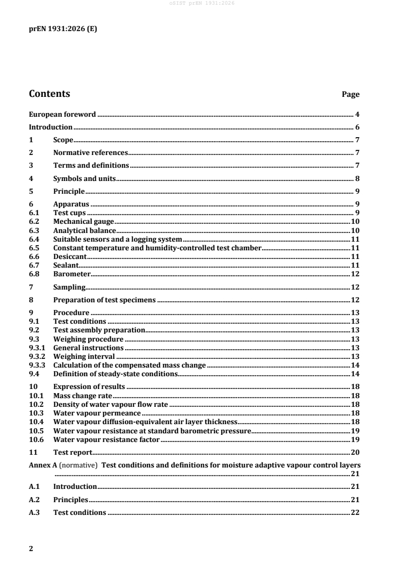
Contents Page
European foreword . 4
Introduction . 6
1 Scope . 7
2 Normative references . 7
3 Terms and definitions . 7
4 Symbols and units . 8
5 Principle . 9
6 Apparatus . 9
6.1 Test cups . 9
6.2 Mechanical gauge . 10
6.3 Analytical balance . 10
6.4 Suitable sensors and a logging system . 11
6.5 Constant temperature and humidity-controlled test chamber . 11
6.6 Desiccant . 11
6.7 Sealant. 11
6.8 Barometer. 12
7 Sampling . 12
8 Preparation of test specimens . 12
9 Procedure . 13
9.1 Test conditions . 13
9.2 Test assembly preparation . 13
9.3 Weighing procedure . 13
9.3.1 General instructions . 13
9.3.2 Weighing interval . 13
9.3.3 Calculation of the compensated mass change . 14
9.4 Definition of steady-state conditions. 14
10 Expression of results . 18
10.1 Mass change rate . 18
10.2 Density of water vapour flow rate . 18
10.3 Water vapour permeance . 18
10.4 Water vapour diffusion-equivalent air layer thickness . 18
10.5 Water vapour resistance at standard barometric pressure. 19
10.6 Water vapour resistance factor . 19
11 Test report . 20
Annex A (normative) Test conditions and definitions for moisture adaptive vapour control layers
............................................................................................................................................................................. 21
A.1 Introduction . 21
A.2 Principles . 21
A.3 Test conditions . 22
A.4 Preparation of test assembly . 24
A.5 Procedure . 24
Annex B (normative) Weighing repeatability and weighing interval needed to achieve the desired
accuracy . 25
Annex C (informative) Correction for the effect of a masked edge of a specimen . 30
Annex D (informative) Recommendations for the use of µ-value and sd-value and definition of
product families . 32
Annex E (informative) Exemplary calculation . 34
E.1 Example of calculation . 34
E.1.1 Data input . 34
E.1.2 Calculate input variables/data . 35
E.2 Weighing data (time stamp and mass in g) according to 9.3 . 36
E.2.1 The blank test assembly is checked for steady-state according to Note 1 in 9.4 . 36
E.3 Calculation of water vapour transmission, G . 37
E.3.1 Δṁ [μg/s] is calculated for each test assembly and each weighing interval by applying
Formulae (1) to (4) . 37
E.3.2 Calculate G according to Formula (5) . 37
E.3.3 The last five Δṁ are checked for steady-state according to 9.4 . 37
E.4 Calculation of water vapour transmission resistance, Z . 38
STP
E.5 Calculation of water vapour transmission resistance factor, μ . 38
Annex F (informative) Precision data . 39
F.1 General . 39
Bibliography . 41
European foreword
This document (prEN 1931:2026) has been prepared by Technical Committee CEN/TC 254 “Flexible
sheets for waterproofing”, the secretariat of which is held by NEN.
This document is currently submitted to the CEN Enquiry.
This document will supersede EN 1931:2000 and EN 1931:2000/AC:2001.
Compared to EN 1931:2000 and EN 1931:2000/AC:2001 the following changes have been made:
— Introduction: Definition of a range of sd-values for which the given method is applicable;
— Clause 1 Scope: General rewording and extension of the range of products for which the given
method is applicable;
— Clause 2 Normative references: updated;
— Clause 3 Terms and definitions: the used terms and definitions are updated and aligned with other
standards for the determination of water vapour transmission properties;
— New Clause 4 Symbols and units: Updated;
— Clause 5 Principle (old Clause 4): Deletion of method A and B;
— Clause 6 Apparatus (old Clause 5): Update of figures and description of the apparatus including
updates concerning accuracy;
— Clause 7 Sampling (old Clause 6): Updated reference including provisions for pre-conditioning;
— Clause 8 Preparation of test specimens (old Clause 7): Deletion of method A and B; increase of
minimum number of test specimens, informative information concerning distribution of specimens
within the product;
— Clause 9 Procedure (old Clause 8): Reference to Annex A for test conditions useful for moisture
adaptive vapour control layers; introduction of provisions for the weighing interval; calculation of
the compensated mass change; definition of steady state;
— Clause 10 Expression of results (old Clause 9): new structure for the calculation of sd and µ;
introduction of the water vapour resistance at standard barometric pressure; deletion of the
precision of test method (allocated to the new Annex F);
— Clause 11 Test report (old Clause 10): Update of the mandatory results to be indicated in the test
report;
— New Annex A: Test conditions and definitions for moisture adaptive vapour control layers
(normative);
— New Annex B: Weighing repeatability and weighing interval needed to achieve the desired accuracy
(normative);
— New Annex C: Correction for the effect of a masked edge of a specimen (normative);
— New Annex D: Recommendations for the use of µ-value and sd-value and definition of product
families (informative);
— New Annex E: Exemplary calculation (informative);
— New Annex F: Precision data (informative);
— Bibliography: Updated references.
Introduction
This document has been prepared by the Technical Committee CEN/TC 254 to determine the water
vapour transmission properties of flexible sheets for waterproofing.
This document has been prepared for factory produced waterproofing sheets but it may also be used for
other products where it is relevant.
The method provided by this document is applicable for sd-values of 0,1 m to 1 500 m.
This document is intended for characterization of flexible sheets for waterproofing as manufactured or
supplied before use. This document relates exclusively to products and not to waterproofing membrane
systems composed of such products and installed in the works.
1 Scope
This document specifies a method for the determination of the water vapour transmission properties of
waterproofing sheets. It is applicable to factory made bitumen, plastic and rubber sheets for roof
waterproofing, damp proof sheets, damp proof courses, underlays and vapour control layers.
2 Normative references
The following documents are referred to in the text in such a way that some or all of their content
constitutes requirements of this document. For dated references, only the edition cited applies. For
undated references, the latest edition of the referenced document (including any amendments) applies.
EN 13416:2023, Flexible sheets for waterproofing — Bitumen, plastic and rubber sheets for roof
waterproofing — Rules for sampling
EN 1849-1, Flexible sheets for waterproofing — Determination of thickness and mass per unit area — Part
1: Bitumen sheets for roof waterproofing
EN 1849-2, Flexible sheets for waterproofing — Determination of thickness and mass per unit area — Part
2: Plastic and rubber sheets for roof waterproofing
3 Terms and definitions
For the purposes of this document, the following terms and definitions apply.
ISO and IEC maintain terminology databases for use in standardization at the following addresses:
— IEC Electropedia: available at http://www.electropedia.org/
— ISO Online browsing platform: available at http://www.iso.org/obp/
3.1
mass change rate
mass of water vapour transmitted through the test assembly per time under specified conditions of
temperature and humidity
3.2
density of water vapour flow rate
mass of water vapour transmitted through a unit area of the test specimen per time under specified
conditions of temperature and humidity
3.3
water vapour permeance
density of water vapour flow rate divided by the water vapour pressure difference between the two test
specimen faces
3.4
water vapour permeability
product of water vapour permeance and the thickness of the test specimen
3.5
water vapour resistance factor
water vapour permeability of the air divided by that of the test specimen
3.6
water vapour diffusion-equivalent air layer thickness
thickness of a motionless air layer which has the same water vapour resistance as the test specimen
3.7
sample
sheet with original packaging as placed on the market
3.8
test piece
part of the sample from which the test specimens are taken
3.9
test specimen
specimen extracted from the test piece with defined dimensions
3.10
test assembly
assembly made of the test cup, sorbent, sealing and test specimen ready for testing
Note 1 to entry: Test assemblies prepared without sorbent, salt solution or water are called blank test assemblies.
3.11
exposed area
effective area of the test specimen that is exposed to the water vapour diffusion flow as used for the
calculation of results
3.12
moisture adaptive vapour control layer (VCL)
VCL designed to have variable diffusion resistance dependent on the surrounding relative humidity
3.13
average relative humidity
mean relative humidity of the relative humidity couples used during the test defining the mean moisture
content of the test specimen
3.15
difference of relative humidity
difference of relative humidity between relative humidity couples used during the test
4 Symbols and units
For the purposes of this document, the following symbols and units apply.
Symbol Quantity Unit
th
n mass of the test assembly kg
m
n
th
n mass of the blank test assembly kg
m
nb,
Time interval between two consecutive weighing’s s
∆t
i
of the test assembly
Blank compensated mass change rate through the kg/s
∆m
i
specimen
G Water vapour flow rate through the specimen in kg/s
steady state conditions
g 2
Density of water vapour flow rate kg/(s·m )
A
Exposed area of the test specimen m
Wp
Water vapour permeance kg/(s·m ·Pa)
Water vapour partial pressure difference Pa
∆ p
v
Water vapour partial pressure Pa
p
v
ϕ
Relative humidity -
θ
Temperature °C
T
Absolute temperature K
Water vapour resistance at standard barometric (s·m ·Pa)/kg
Z
STP
pressure
Water vapour diffusion-equivalent air layer m
s
d
thickness
Water vapour permeability of the air at standard kg/(m·s·Pa)
δ
a,STP
barometric pressure
Standard barometric pressure = 1 013,25 hPa
p
p
Mean barometric pressure within the observed hPa
time frame
Gas constant of water vapour = 461,5 N·m/(kg·K)
R
D
δ
Water vapour permeability kg/(m·s·Pa)
d
Thickness of the specimen m
µ
Water vapour resistance factor -
5 Principle
The test specimen is sealed to the open side of a test cup containing either a desiccant (dry cup) or an
aqueous saturated solution or water (wet cup). The assembly is then placed in a temperature and
humidity-controlled test chamber. Because of the different partial vapour pressure between the test cup
and the chamber, a vapour flow occurs through permeable specimens. Periodic weighings of the assembly
are made to determine the water vapour flow rate in the steady-state to calculate water vapour
transmission properties. Information about the precision of the method is included in the informative
Annex F.
6 Apparatus
6.1 Test cups
Test cups resistant to corrosion from the desiccant or salt solutions they contain with a minimum free
test area of at least 0,005 m . Distance between the bottom of the cup and the lower surface of the
specimen shall be minimum 16 mm. It is essential that the test assembly provides a well-defined exposed
area on the upper specimen surface free of sealant. Total weight of specimen-mounted cup and desiccant
or salt solution as shown in Figure 1 must not exceed capability of the analytical balance used.
NOTE 1 The water vapour permeability of the test cup must be significantly lower than the water vapour
permeability of the specimen tested. Typically, cups are made of glass or metal. For water proofing membranes
preferably test cups made of pure, cold drawn aluminium of 1 mm thickness are used.
NOTE 2 In case of using salt solutions, corrosion and crystallization effects can occur. For more information see
Annex A.
NOTE 3 In case of deep test cups, the use of spacers made of lightweight non-hygroscopic materials on the
bottom (e.g. open foam material) helps to limit the use of desiccant to the necessary amount of minimum 12 mm
height.
Dimensions in millimetres
Key
1 inner template
2 sealing (see 6.7)
3 test specimen
4 desiccant (see 6.6)
Figure 1 — Example for a test assembly consisting of an aluminium cup with a sealed test
specimen and an absorption atmosphere with an exposed area formed by an inner template
6.2 Mechanical gauge
Mechanical gauge to determine the thickness of test specimens with a resolution of 0,01 mm.
6.3 Analytical balance
Analytical balance, capable of weighing the test assembly with the repeatability needed for the required
accuracy.
Wherever possible, a balance of 0,000 1 g resolution should be used. For heavy test assemblies, a balance
resolution of 0,001 g may be sufficient. (see Annex B for information linking the balance resolution to the
duration of test).
NOTE The factors that affect the necessary accuracy of measurement are discussed in Annex B.
6.4 Suitable sensors and a logging system
Suitable sensors and a logging system to continuously record the temperature and relative humidity
within the test chamber. The sensors shall be calibrated at regular intervals.
6.5 Constant temperature and humidity-controlled test chamber
Temperature in the test chamber shall be maintained at 23 °C (±1 K), with the average at the end of the
test period being within ±0,5 K of the specified test condition. Relative humidity in the test chamber shall
be maintained at 75 % (±5 % r.h.), with the average at the end of the test period being within ±2 % r.h. of
the specified test condition.
Alternatively, use a room or chamber that can be maintained at 23 °C (±1 K) together with an exsiccator
containing a sodium chloride solution, saturated at 23 °C and containing a large excess of undissolved
sodium chloride.
Air shall be continuously circulated throughout the chamber, with a velocity sufficient to maintain
uniform conditions within the chamber. Test assemblies shall be placed in the chamber in such a way that
air flow is not restricted over the top of the test assemblies.
A sufficient air speed to maintain uniform conditions should be above 0,2 m/s.
In case of high permeable materials (s < 0,2 m) the air speed above the test assemblies should be
d
minimum 2 m/s to avoid a stagnating air layer formation that could influence the test results.
6.6 Desiccant
Anhydrous calcium chloride with particles size of about 5 mm in diameter, free of fines that will pass a
600 µm sieve. The relative humidity in the cup atmosphere shall not exceed 1 %.
As the packaging of desiccants oftentimes does not fully avoid moisture uptake of the desiccant, it can be
useful to dry the desiccant before use. Desiccant should be stored in a sealed container and be at room
temperature before use.
6.7 Sealant
Sealant, which is impermeable to water vapour, does not undergo physical or chemical changes during
the test and does not cause physical or chemical changes to the specimen. An example for a sealing shows
Figure 2.
NOTE 1 Examples for sealants are crystalline wax, crystalline parafine, sealing cord/tape of Butyl or
Polyisobutylene or bituminous binder.
NOTE 2 To achieve a well-defined exposed area on the upper specimen surface free of sealant, inner templates
can be used during the sealing process.
NOTE 3 Mechanical sealings by gaskets may not be suitable for specific materials. In case such sealings are used
these have to be validated against crystalline wax for the specific material tested.
To proof the feasibility of a specific sealant it is recommended that initial tests are carried out with an
impermeable metal specimen to test that the resultant vapour flow rate is negligible compared to the
expected vapour flow through the specimen.
Key
1 inner template
2 test specimen
3 sealing compound
4 cup according to Figure 1 (see 6.1)
Figure 2— Example for a sealing
6.8 Barometer
Capable of measuring barometric pressure with a resolution of ±1 hPa.
The barometric pressure at the testing laboratory shall be measured daily or at least at every weighing
(whatever timeframe is smaller) during the test or obtained from a closely adjacent meteorological
station corrected to the height of the test chamber.
7 Sampling
Test samples shall be taken in accordance with EN 13416:2023. If any conditioning is necessary
according to technical information given by the manufacturer such conditioning shall take place before
testing.
8 Preparation of test specimens
In the absence of definitions given by product standards or other harmonized technical specification, a
minimum of 5 test specimens shall be taken from the product. Test specimens shall be cut to correspond
with the dimensions of the chosen test assembly.
The distribution of test specimens shall be representative of the material tested.
NOTE 1 For membranes from continuous production processes, normally the distribution over the width of the
product is relevant.
In absence of information about potential variation of product characteristics within the products a
distribution of samples over the width and the length of the membrane is recommendable (diagonal
arrangement of samples).
In addition, a specimen for the preparation of the blank test assembly shall be taken wherefrom it is
representative for the test specimens taken.
NOTE 2 The specimen for the preparation of the blank test assembly becomes the sixth specimen of a standard
five dish test set.
9 Procedure
9.1 Test conditions
In case of reference to EN 1931 without further definitions about test conditions the following test
conditions are to be used.
Climatic chamber or evaporation area: 23 °C / 75 % R.H.
Closed absorption area of cup: 23 °C / 0 % R.H.
Test conditions for moisture adaptive vapour control layers are given in the normative Annex A.
9.2 Test assembly preparation
The direction the specimens are installed in the test assembly shall correspond to the direction of the
vapour flow in the intended use.
In case the µ value is to be calculated, the thickness of the layer that contributes to the water vapour
transmission resistance shall be determined.
Determine the thickness for bituminous products according to EN 1849-1 and for plastic and rubber
waterproofing sheets according to EN 1849-2.
NOTE Recommendations for the use of µ-value and sd-value and definition of product families are given in the
informative Annex D.
Place a layer of desiccant (6.6) of minimum 12 mm thickness on the bottom of the cup (6.1). Leave a space
of minimum 3 mm to 4 mm between desiccant and specimen. The desiccant shall not touch the bottom
surface of the test specimen. Provisions for the use of saturated salt solutions or water are given in the
informative Annex A.
Seal the test specimen in the cup in a way that the achieved exposed area of the test specimen is within
1 % of the exposed area used for the calculation of results. Sealants shall be applied in such a way that
the difference between the upper and lower exposed area of the test specimen is as small as possible.
Seal the specimen for the blank test assembly without desiccant and handle in the same way as the test
assemblies during the test procedure. Weight of the blank test assembly shall correspond to the weight
of the test assemblies to ±5 g.
NOTE 3 To compensate the weight of the sorbent, additional non hygroscopic weights (e.g. metal balls or
washers) can be used inside the test cup of the blank test assembly.
9.3 Weighing procedure
9.3.1 General instructions
Weigh the test assemblies with the required accuracy according to Annex B. Place the cup in a test
chamber according to 6.5 maintained at the required test conditions according to 9.1.
NOTE Climate conditions in the test cup can change when:
— in a dry cup test, the assembly has gained more than 1,5 g per 25 ml of desiccant in the cup, or
— in a wet cup test, the airgap exceeds 20 mm due to mass loss.
9.3.2 Weighing interval
Continue weighing of the test assemblies in time intervals ∆∆t ≥ t calculated according to Annex B until
min
steady-state conditions according to 9.4 are reached.
9.3.3 Calculation of the compensated mass change
From the second weighing on calculate the mass changes between two consecutive weighings of each test
assembly according to Formula (1) and the mass change between two consecutive weighings of the blank
test assembly according to Formula (2).
∆m ()m− m (1)
i nn−1
where
th
∆m is the i mass change of the test assembly in kg;
i
th
m is the n mass of the test assembly in kg.
n
∆m ()mm− (2)
b,i bn,,b n−1
where
th
∆m is the i mass change of the blank test assembly in kg;
b,i
th
m is the n mass of the blank test assembly in kg.
b,n
The weight changes of each test assembly shall be corrected by the weight changes of the blank test
assembly according to Formula (3).
(3)
∆m ∆∆mm−
c,,i i bi
where
th
is the i compensated mass change in kg.
∆m
c,i
NOTE Weighing intervals that are too long, can lead to a saturation of the sorbent that can influence the relative
humidity inside the test cup.
If conditioning and the weighing procedure are not conducted in the same temperature and humidity
controlled rooms, the time frame the specimens are not exposed to the test conditions shall be as short
as possible.
9.4 Definition of steady-state conditions
From the second weighing on, calculate the compensated mass change rate ∆m in kg/s according to
i
Formula (4).
∆m
c,i
∆m = (4)
i
∆t
i
where
th
∆m is the i comp
...