

ISO 1966:2026
(Main)Crimped joints for aircraft electrical cables
- Abstract
This document specifies the design requirements (and tests) for the crimping of insulated and non-insulated joints to general purpose electrical cables for aircraft, with conductors of copper, copper alloy, aluminium or aluminium alloy, in locations in which the stabilized conductor temperature does not exceed the values specified for the relevant type of cable, i.e. 105 °C, 190 °C or 260 °C. This document specifies the type of cable to use for the joints (see 4.1). The document also contains recommendations relating to the inspection of such connections and the tools used to perform the crimping operation. Because satisfactory crimping is dependent upon the maintenance and setting of tools, it also contains recommendations for tests to confirm their serviceability. NOTE Testing of crimped joints to assess their suitability for aircraft shows that certain environmental conditions, for example vibration, have no significant effect on the performance of the joints. Therefore, such tests are not provided in this document.
- Status
- Published
- Publication Date
- 09-Jul-2026
- Technical Committee
- ISO/TC 20/SC 1 - Aerospace electrical requirements
- Drafting Committee
- ISO/TC 20/SC 1 - Aerospace electrical requirements
- Current Stage
- 6060 - International Standard published
- Start Date
- 10-Jul-2026
- Due Date
- 21-Nov-2026
- Completion Date
- 10-Jul-2026
ISO 1966:2026 is an International Standard from ISO for crimped joints on aircraft electrical cables. It specifies design requirements, test methods and control checks for insulated and non-insulated crimped joints on copper, copper alloy, aluminium or aluminium alloy conductors used with cables rated up to 105 °C, 190 °C or 260 °C stabilized conductor temperature. Aerospace manufacturers, engineers, quality managers, buyers and inspectors use it to choose compatible cables, tools and dies and to judge whether the finished joint is acceptable.
What does ISO 1966:2026 specify?
ISO 1966:2026 specifies the requirements for making crimped joints for general purpose aircraft electrical cables, together with the tests used to verify them. Clause 1 sets the scope, Clauses 2 and 3 cover references and terms, Clauses 4 to 7 cover design, dimensions, performance and marking, and Clauses 8 to 11 cover type tests, production control tests and users’ control tests.
The scope includes insulated and non-insulated joints and also covers the cable types to be used for the joint. A note states that environmental tests such as vibration are not included because testing showed they have no significant effect on joint performance.
What are the key requirements of ISO 1966:2026?
Design and tooling requirements
Clause 4 sets the main design rules for the joint, the barrel, the insulation support and the crimping tools. These points matter because the joint has to be electrically sound, mechanically secure and inspectable in service.
- The crimp barrel material and surface finish have to suit the joint, and the barrel plating is limited to tin, tin-alloy, silver, gold or palladium unless another coating has proven suitability.
- Aluminium or aluminium alloy terminals are to be plated with tin or nickel, and the electrochemical potential difference between contacting conducting surfaces is limited.
- The joint design has to make conductor engagement easy to check by inspection, and aluminium terminations are to be designed to prevent corrosion.
- Materials used before or after insulation have to resist corrosion, abrasion, fungus and aircraft fluids, and they must not support combustion.
- The manufacturer has to provide material specifications, protective treatment, cable sizes, tool and die references, crimp marking code, cable end preparation information, maximum overall dimensions and instructions for the recommended tool.
Clause 4.2 requires the completed joint to combine the conductor crimp and insulation grip in one operation where applicable. For size 12 cables or smaller, an insulation grip is required unless equivalent insulation support is provided.
Clause 4.4 sets the tool and die requirements. Tools have to locate the crimp correctly, hold the termination until the crimp is formed, avoid damage to insulation or plating, and avoid fracture or sharp edges. The tool maker’s name and serial number have to be on the tool, and the gauging method has to be declared.
Dimensions, marking and performance
Clause 5 requires the completed joint to conform to the overall dimensional rules taken from IEC 60352-2, and the barrel must not be bent, twisted or otherwise deformed in a way that raises doubt about quality. Clause 7 requires the completed joint to be marked, when practicable, with the declared code for the crimping tool or die used.
Clause 6 links mechanical strength and electrical performance to the values in Tables 2 and 3. In practice, this means the accepted voltage drop and tensile strength depend on conductor material and size.
Testing and control
Clause 8 says evidence of successful type testing should be available, and it points to production control tests and user control tests to keep quality consistent. Clause 9 then sets the type test conditions, specimen counts and test sequence.
The test program includes inspection, voltage drop, climatic testing, load and temperature cycling, current ageing, rapid temperature change, salt mist, vibration with current, tensile testing, insulation grip tests, and extra tests for insulated joints such as fluid resistance, heat ageing, low-temperature crimping, dielectric strength and flammability. Clauses 10 and 11 cover production control of supplied terminations, cable splices, tools and dies, plus routine visual inspection and periodic tensile checks by users.
What terms does ISO 1966:2026 define?
- Termination - a permanent connection made between a cable conductor and a terminal end or a pin or socket contact.
- Terminal end - a connecting device with a barrel that accepts a conductor, with or without added insulation support.
- Pin or socket contact - a contact for a plug or socket that has a barrel to accept the conductor.
- Cable splice - a connecting device with barrel(s) that join conductor ends in line.
- Crimped joint - a permanent solderless assembly made by crimping a conductor into a crimp contact, terminal end or splice.
- Crimping tool - a manual or power-operated device used to make the crimp or the insulation grip.
- Positioner - a locator or similar device that sets and controls the crimp position in the barrel.
Who uses ISO 1966:2026?
ISO 1966:2026 is used by aerospace manufacturers, cable and connector suppliers, test laboratories, quality control teams and inspectors. They use it to specify the correct cable and barrel combination, select tools and dies, verify crimp quality, and check production or incoming parts against a common aircraft standard.
What changed in ISO 1966:2026 from the previous edition?
ISO 1966:2026 is the second edition and it replaces ISO 1966:1973. The changes stated in the document are:
- addition of Clause 2;
- addition of requirements for different crimp barrel materials and coating materials in 4.1;
- addition of subclause 4.3;
- addition of requirements for the overall dimensions of the crimped joints in Clause 6;
- revision of the type test requirements in Clause 9;
- revision of the tables for test current, voltage drop and tensile strength.
Which standards are used with ISO 1966:2026?
- IEC 60068-2-6:2022 - provides the sinusoidal vibration test method used in Clause 9.10.
- IEC 60068-2-11:2021 - provides the salt mist test method used in Clause 9.9.
- IEC 60352-2:2024 - provides general requirements and test methods for crimped connections, including the climatic test in Clause 9.5 and the overall dimension rule used in Clause 5.
- ISO 2635 - gives dimensions and characteristics for aircraft conductors for general purpose electrical cables and aerospace applications, and is named for copper cables in Clause 4.3.
What does the ISO 1966:2026 document contain?
ISO 1966:2026 contains the full test framework for qualifying and controlling crimped joints, including specimen preparation, measurement points and acceptance criteria. Table 1 sets the sequence and specimen allocation for the type tests, while Tables 2 and 3 give the current, voltage-drop limits and tensile strength values for copper and aluminium conductors.
The figures support practical testing: Figure 1 shows the rapid temperature change cycle, Figure 2 shows where to measure voltage drop, and Figure 3 shows the insulation grip test method. Clause 9 also gives detailed procedures for climatic, cycling, salt mist, vibration, tensile, dielectric strength and flammability tests, so the document is used for design verification, testing, production control and user inspection.
Relations
- Effective Date
- 25-Nov-2023
Get Certified
Connect with accredited certification bodies for this standard

BUREAU VERITAS Certification Germany
Bureau Veritas certification in Germany.

Element Materials Technology
Materials testing and product certification.

AQMS Ltd.
AQMS provides ISO certification to SMEs across the UK.
Sponsored listings
Frequently Asked Questions
ISO 1966:2026 is a standard published by the International Organization for Standardization (ISO). Its full title is "Crimped joints for aircraft electrical cables". This standard covers: This document specifies the design requirements (and tests) for the crimping of insulated and non-insulated joints to general purpose electrical cables for aircraft, with conductors of copper, copper alloy, aluminium or aluminium alloy, in locations in which the stabilized conductor temperature does not exceed the values specified for the relevant type of cable, i.e. 105 °C, 190 °C or 260 °C. This document specifies the type of cable to use for the joints (see 4.1). The document also contains recommendations relating to the inspection of such connections and the tools used to perform the crimping operation. Because satisfactory crimping is dependent upon the maintenance and setting of tools, it also contains recommendations for tests to confirm their serviceability. NOTE Testing of crimped joints to assess their suitability for aircraft shows that certain environmental conditions, for example vibration, have no significant effect on the performance of the joints. Therefore, such tests are not provided in this document.
This document specifies the design requirements (and tests) for the crimping of insulated and non-insulated joints to general purpose electrical cables for aircraft, with conductors of copper, copper alloy, aluminium or aluminium alloy, in locations in which the stabilized conductor temperature does not exceed the values specified for the relevant type of cable, i.e. 105 °C, 190 °C or 260 °C. This document specifies the type of cable to use for the joints (see 4.1). The document also contains recommendations relating to the inspection of such connections and the tools used to perform the crimping operation. Because satisfactory crimping is dependent upon the maintenance and setting of tools, it also contains recommendations for tests to confirm their serviceability. NOTE Testing of crimped joints to assess their suitability for aircraft shows that certain environmental conditions, for example vibration, have no significant effect on the performance of the joints. Therefore, such tests are not provided in this document.
ISO 1966:2026 is classified under the following ICS (International Classification for Standards) categories: 49.060 - Aerospace electric equipment and systems. The ICS classification helps identify the subject area and facilitates finding related standards.
ISO 1966:2026 has the following relationships with other standards: It is inter standard links to ISO 1966:1973. Understanding these relationships helps ensure you are using the most current and applicable version of the standard.
ISO 1966:2026 is available in PDF format for immediate download after purchase. The document can be added to your cart and obtained through the secure checkout process. Digital delivery ensures instant access to the complete standard document.
Standards Content (Sample)
International
Standard
ISO 1966
Second edition
Crimped joints for aircraft electrical
2026-07
cables
Raccordements sertis pour câbles électriques utilisés à bord des
aéronefs
Reference number
© ISO 2026
All rights reserved. Unless otherwise specified, or required in the context of its implementation, no part of this publication may
be reproduced or utilized otherwise in any form or by any means, electronic or mechanical, including photocopying, or posting on
the internet or an intranet, without prior written permission. Permission can be requested from either ISO at the address below
or ISO’s member body in the country of the requester.
ISO copyright office
CP 401 • Ch. de Blandonnet 8
CH-1214 Vernier, Geneva
Phone: +41 22 749 01 11
Email: copyright@iso.org
Website: www.iso.org
Published in Switzerland
ii
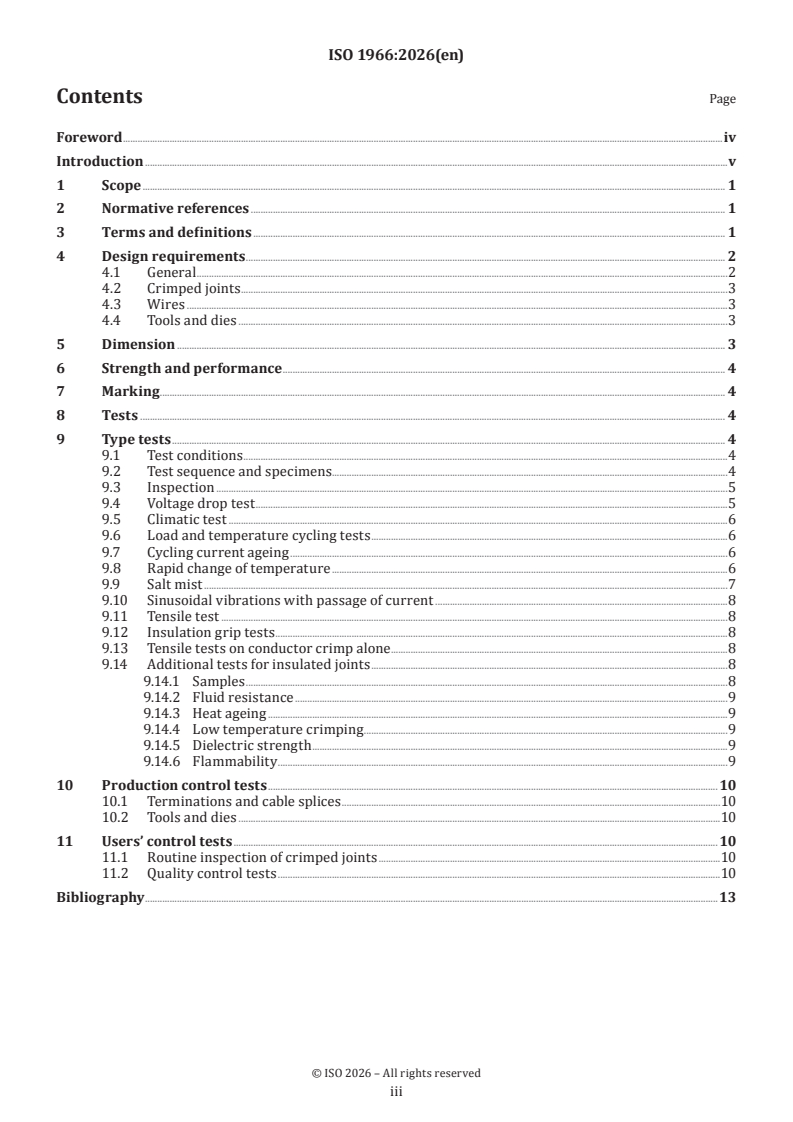
Contents Page
Foreword .iv
Introduction .v
1 Scope . 1
2 Normative references . 1
3 Terms and definitions . 1
4 Design requirements . 2
4.1 General .2
4.2 Crimped joints . .3
4.3 Wires .3
4.4 Tools and dies .3
5 Dimension . 3
6 Strength and performance . 4
7 Marking . . 4
8 Tests . 4
9 Type tests . 4
9.1 Test conditions .4
9.2 Test sequence and specimens.4
9.3 Inspection .5
9.4 Voltage drop test .5
9.5 Climatic test .6
9.6 Load and temperature cycling tests .6
9.7 Cycling current ageing .6
9.8 Rapid change of temperature .6
9.9 Salt mist .7
9.10 Sinusoidal vibrations with passage of current .8
9.11 Tensile test .8
9.12 Insulation grip tests .8
9.13 Tensile tests on conductor crimp alone .8
9.14 Additional tests for insulated joints .8
9.14.1 Samples .8
9.14.2 Fluid resistance .9
9.14.3 Heat ageing .9
9.14.4 Low temperature crimping .9
9.14.5 Dielectric strength .9
9.14.6 Flammability .9
10 Production control tests . 10
10.1 Terminations and cable splices .10
10.2 Tools and dies .10
11 Users’ control tests . 10
11.1 Routine inspection of crimped joints .10
11.2 Quality control tests .10
Bibliography .13
iii
Foreword
ISO (the International Organization for Standardization) is a worldwide federation of national standards
bodies (ISO member bodies). The work of preparing International Standards is normally carried out through
ISO technical committees. Each member body interested in a subject for which a technical committee
has been established has the right to be represented on that committee. International organizations,
governmental and non-governmental, in liaison with ISO, also take part in the work. ISO collaborates closely
with the International Electrotechnical Commission (IEC) on all matters of electrotechnical standardization.
The procedures used to develop this document and those intended for its further maintenance are described
in the ISO/IEC Directives, Part 1. In particular, the different approval criteria needed for the different types
of ISO documents should be noted. This document was drafted in accordance with the editorial rules of the
ISO/IEC Directives, Part 2 (see www.iso.org/directives).
ISO draws attention to the possibility that the implementation of this document may involve the use of (a)
patent(s). ISO takes no position concerning the evidence, validity or applicability of any claimed patent
rights in respect thereof. As of the date of publication of this document, ISO had not received notice of (a)
patent(s) which may be required to implement this document. However, implementers are cautioned that
this may not represent the latest information, which may be obtained from the patent database available at
www.iso.org/patents. ISO shall not be held responsible for identifying any or all such patent rights.
Any trade name used in this document is information given for the convenience of users and does not
constitute an endorsement.
For an explanation of the voluntary nature of standards, the meaning of ISO specific terms and expressions
related to conformity assessment, as well as information about ISO's adherence to the World Trade
Organization (WTO) principles in the Technical Barriers to Trade (TBT),see www.iso.org/iso/foreword.html.
This document was prepared by Technical Committee ISO/TC 20, Aircraft and space vehicles, Subcommittee
SC 1, Aerospace electrical requirements.
This second edition cancels and replaces the first edition (ISO 1966:1973), which has been technically
revised.
The main changes are as follows:
— addition of Clause 2;
— addition of requirements for different crimp barrel materials and coating materials (see 4.1);
— addition of subclause 4.3;
— addition of requirements for the overall dimensions of the crimped joints (see Clause 6);
— revision of requirements for type test (see Clause 9);
— revision of the tables for test current, voltage drop and tensile strength tensile (Table 2 and Table 3).
Any feedback or questions on this document should be directed to the user’s national standards body. A
complete listing of these bodies can be found at www.iso.org/members.html.
iv
Introduction
This document serves as an essential reference standard for aerospace manufacturers, engineers and
quality control professionals to promote consistency and safety of aircraft electrical systems.
v
International Standard ISO 1966:2026(en)
Crimped joints for aircraft electrical cables
1 Scope
This document specifies the design requirements (and tests) for the crimping of insulated and non-insulated
joints to general purpose electrical cables for aircraft, with conductors of copper, copper alloy, aluminium
or aluminium alloy, in locations in which the stabilized conductor temperature does not exceed the values
specified for the relevant type of cable, i.e. 105 °C, 190 °C or 260 °C. This document specifies the type of cable
to use for the joints (see 4.1).
The document also contains recommendations relating to the inspection of such connections and the tools
used to perform the crimping operation. Because satisfactory crimping is dependent upon the maintenance
and setting of tools, it also contains recommendations for tests to confirm their serviceability.
NOTE Testing of crimped joints to assess their suitability for aircraft shows that certain environmental
conditions, for example vibration, have no significant effect on the performance of the joints. Therefore, such tests are
not provided in this document.
2 Normative references
The following documents are referred to in the text in such a way that some or all of their content constitutes
requirements of this document. For dated references, only the edition cited applies. For undated references,
the latest edition of the referenced document (including any amendments) applies.
IEC 60068-2-6:2022, Environmental testing — Part 2-6: Tests — Test Fc: Vibration (sinusoidal)
IEC 60068-2-11:2021, Tests - Test Ka: Salt mist
IEC 60352-2:2024, Solderless connections — Part 2: Crimped connections — General requirements, test methods
and practical guidance
3 Terms and definitions
For the purposes of this document, the following terms and definitions apply.
ISO and IEC maintain terminology databases for use in standardization at the following addresses:
— ISO Online browsing platform: available at https:// www .iso .org/ obp
— IEC Electropedia: available at https:// www .electropedia .org/
3.1
termination
permanent connection formed by the end of an electrical cable conductor with a terminal end (3.2) or a pin
or socket contact (3.3)
3.2
terminal end
connecting device with barrel(s) accommodating an electrical cable conductor with or without additional
provision to accommodate and secure the insulation
3.3
pin or socket contact
contact used in a plug or socket (receptacle) with a barrel at one end to accommodate an electrical cable
conductor with or without additional provision to secure the insulation
3.4
cable splice
connecting device with barrel(s) each accommodating an electrical cable conductor(s) with or without
additional provision to accommodate and secure the insulation
3.5
crimped joint
permanent solderless assembly made by crimping a conductor of an electrical cable into a crimp contact,
terminal end, or splice
3.6
crimping
method of firmly attaching a terminal end (3.2) or cable splice (3.4) to a conductor by re-shaping the barrel
around the conductor to establish good electrical and mechanical contact
3.7
insulation grip
part of a terminal barrel or cable splice (3.4) barrel into which the insulation of the cable is placed and which,
by reforming, grips the insulation
3.8
crimping tool
manually operated or power-operated mechanical device for making a crimp or insulation grip (3.7)
3.9
positioner
locator, turret or other device permanently or removably attached to a crimping tool (3.8), serving correctly
to locate and control the position of the crimp on the barrel
4 Design requirements
4.1 General
The protective treatment and surface finish of the terminal end, pin or socket contact or cable splice should
be of such a quality that the joint conforms with the requirements of this document.
The crimp barrel shall be plated with tin, tin-alloy, silver, gold or palladium. Other plating materials, such as
nickel (unless used as under-plate) may be used provided their suitability has been proven.
The aluminium or aluminium alloy terminal should be plated with tin or nickel.
The electrochemical potential difference between all conducting surfaces in contact should not exceed
0,25 V.
The design of the terminal end, pin or socket contact or cable splice shall be such that adequate engagement
of the cable conductor in the completed joint can be readily established by inspection.
Terminations for aluminium conductors shall be designed to prevent corrosion. The use of antioxidant
compounds or hermetic sealing is recommended.
Any material used for pre- or post-insulation shall be non-corrosive, resistant to abrasion, fungus and aircraft
fluids and shall not support combustion. The insulation, and internal sleeve if any, shall remain firmly fixed
in its correct position before and after crimping. The insulation should be colour-coded in respect of its
conductor size or sizes in accordance with the relevant national standards.
The manufacturer shall make the following information available:
a) terminal end, pin or socket contact or cable splice material specification;
b) protective treatment;
c) size and type of cable for which each item is available;
d) appropriate crimping tool or die references and settings;
e) the identification code of crimp marking;
f) information on the preparation of cable ends before crimping;
g) maximum overall dimensions of the completed crimp;
h) instruction sheets for the proper use of the recommended crimping tool.
4.2 Crimped joints
The completed crimped joint should take the form of a conductor crimp and insulation grip effected in one
operation, using the die or dies stipulated by the tool manufacturer. All terminal ends or cable splices for
size 12 cables or smaller shall have an insulation grip unless equivalent insulation support is otherwise
provided.
4.3 Wires
Copper cables should conform with the requirements of ISO 2635 or other international standards.
Aluminium cables should conform with the requirements of relevant international standards.
4.4 Tools and dies
Tools shall be so designed that:
a) they will correctly locate and control the position of the crimp;
b) they will not release the termination during normal operation until the crimp has been correctly
formed;
c) they will not axially deform pin or socket contacts or increase the effective diameter along the length of
the crimped section by more than the amount specified in the connector specification;
d) during the formation of the conductor crimp, they will apply the appropriate mark, where required by
Clause 7, to indicate the die size or tool which has been used;
e) they will not adversely affect the external protective treatment or insulation during the crimping
operation;
f) they will not fracture the terminal
...