

IEC 61803:2026
(Main)Determination of power losses in high-voltage direct current (HVDC) converter stations
- Abstract
IEC 61803:2026 applies to all high-voltage direct current (HVDC) converter stations with line-commutated converters (LCC) as well with voltage-sourced converters (VSC) used for power exchange (power transmission or back-to-back installation) in utility systems. For line-commutated converters (LCC), this document presumes the use of 12-pulse thyristor converters but can, with due care, also be used for 6-pulse thyristor converters. Where VSC is referred to in this document, it is assumed to be of the MMC-type or similar, with very low harmonic generation. It is important to treat other types of VSC as appropriate. In some applications, synchronous compensators, static var compensators (SVC), or static synchronous compensator (STATCOM) are connected to the AC bus of the HVDC converter station. The loss determination procedures for such equipment are not included in this document. This document presents a set of standard procedures for determining the total losses of an HVDC converter station, except for VSC valves which are covered by the IEC 62751 series. The procedures cover all parts, except as noted above, and address no-load operation and operating losses together with their methods of calculation which use, wherever possible, measured parameters. Converter station designs employing novel components or circuit configurations compared to the typical design assumed in this document, or designs equipped with unusual auxiliary circuits that can affect the losses, are assessed on their own merits.
This edition includes the following significant technical changes with respect to the previous edition:
a) HVDC stations with voltage-sourced converters (VSC) technology have been included;
b) to facilitate the application of this document and to ensure its quality remains consistent, 5.1.8 and 5.8 have been reviewed, taking into consideration that the present thyristor production technology provides considerably less thyristor parameters dispersion comparing with the situation in 1999 when the first edition of IEC 61803 was developed; therefore, the production records of thyristors can be used for the power losses calculation;
c) the calculation of the total station load losses (cases D1 and D2 in Annex C) has been corrected.
- Status
- Published
- Publication Date
- 25-May-2026
- Drafting Committee
- MT 14 - TC 22/SC 22F/MT 14
- Current Stage
- PPUB - Publication issued
- Start Date
- 26-May-2026
- Completion Date
- 08-May-2026
Buy Documents
IEC 61803:2026 - Determination of power losses in high-voltage direct current (HVDC) converter stations
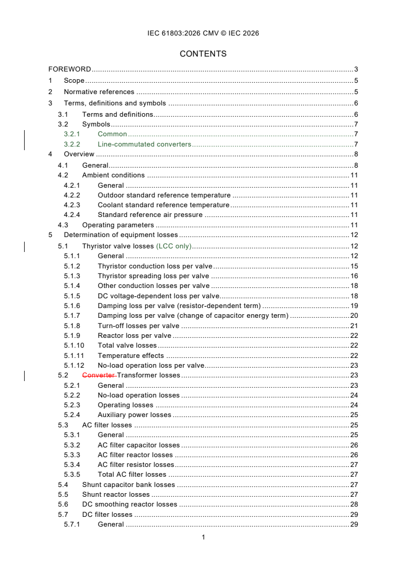
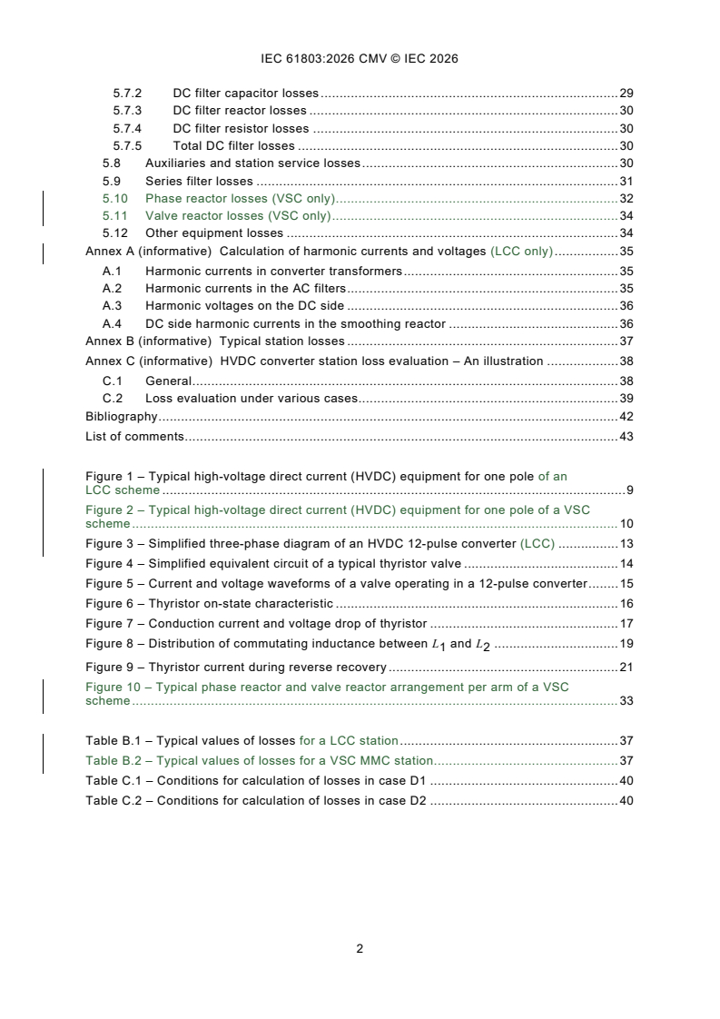
REDLINE IEC 61803:2026 CMV - Determination of power losses in high-voltage direct current (HVDC) converter stations
IEC 61803:2026 - Détermination des pertes en puissance dans les stations de conversion en courant continu a haute tension (CCHT)
IEC 61803:2026 is an IEC International Standard for determining power losses in HVDC converter stations. It applies to stations with line-commutated converters (LCC) and voltage-sourced converters (VSC) used for power transmission or back-to-back operation in utility systems. The document gives a common calculation method so suppliers and purchasers can compare, verify and document losses on the same basis.
What does IEC 61803:2026 specify?
IEC 61803:2026 specifies standard procedures for calculating the total losses of an HVDC converter station. It covers no-load operation losses and operating losses, using measured parameters wherever practical.
The scope includes LCC stations, assumed to use 12-pulse thyristor converters, and VSC stations, assumed to be MMC-type or similar with very low harmonic generation. It does not include loss determination for synchronous compensators, SVC or STATCOM connected to the AC bus, and VSC valve losses are covered by the IEC 62751 series. Station designs with novel components or unusual auxiliary circuits are to be assessed on their own merits.
| Annex | What it covers |
|---|---|
| Annex A | Calculation of harmonic currents and voltages for LCC only |
| Annex B | Typical station losses |
| Annex C | HVDC converter station loss evaluation, with an illustration |
The document is organized into clauses on scope, normative references, terms and symbols, overview, and detailed loss determination for each major item of equipment.
What are the key requirements of IEC 61803:2026?
IEC 61803:2026 requires losses to be evaluated under defined ambient and operating conditions, then summed by equipment item. That matters in practice because the result is meant to be repeatable for bids, guarantees and performance checks, not a rough site estimate.
- Use standard reference ambient conditions in Clause 4.2. The document sets an outdoor dry-bulb temperature of 20 °C, uses the purchaser’s wet-bulb value where needed, and applies standard atmospheric pressure corrected for altitude above 1 000 m. In practice, the same station can give different losses at different temperatures, so the reference conditions keep comparisons fair.
- Calculate losses for defined load levels in Clause 4.3. LCC load level is defined by direct current, direct voltage, firing angle, AC system voltage and transformer tap position; VSC load level is defined by direct current, direct voltage, AC system voltage, transformer tap position where relevant, converter AC voltage, converter AC current and phase angle. If no load levels are specified, the document uses rated load.
- Separate operating losses from no-load operation losses in Clause 3 and Clause 4.3. No-load operation means the converter is blocked, the transformer is energised, and only the equipment needed for immediate pickup is connected; operating losses apply when the converter is in service. This distinction matters because many projects price standby losses differently from load-dependent losses.
- Determine LCC thyristor valve losses item by item in Clause 5.1. The valve loss calculation covers conduction, spreading, other conduction, DC voltage-dependent loss, damping loss, turn-off loss, reactor loss, temperature effects and no-load operation loss. The document relies on measured valve data and production records where appropriate, which means the supplier must assemble test results and device data rather than use one generic value.
- Treat transformers according to operating mode in Clause 5.2. No-load losses follow IEC 60076-1, while load losses include harmonic effects and are calculated from fundamental-frequency and higher-frequency measurements. For VSC, harmonic losses may be treated like conventional AC transformers when current THD is below 5 %; otherwise the harmonic spectrum has to be calculated and stated.
- Evaluate filters and reactive equipment by their actual components in Clauses 5.3 to 5.7. AC filters, shunt capacitor banks, shunt reactors, DC smoothing reactors and DC filters are all calculated from measured component values and harmonic currents or voltages. That means the station design team must know which branches are energised at each load level and what harmonic content reaches each branch.
- Use the VSC reactor rules where applicable in Clauses 5.10 and 5.11. Phase reactor losses and valve reactor losses are calculated from measured impedance, quality factor and winding temperature. This is relevant for VSC topologies that use phase reactors, valve reactors or both.
- Include auxiliaries and only relevant special equipment in Clauses 5.8 and 5.12. Station service loads are averaged over normal operation, while special-purpose loads used only for outages or transient events are excluded. Other equipment losses are normally neglected unless the station includes special equipment not covered by the typical configuration.
What terms does IEC 61803:2026 define?
IEC 61803:2026 defines the terms it uses for station-loss accounting so that the same words mean the same thing across suppliers and purchasers.
- Auxiliary losses - electric power needed to feed converter-station auxiliary loads.
- Equipment no-load operation losses - losses in an item of equipment when the station is energised but the converters are blocked.
- Load level - the set of AC system and converter operating conditions at which the station operates.
- Equipment operating losses - losses in an item of equipment at a given load level when the converters are operating.
- Rated load - the load corresponding to nominal operating conditions.
- Total station no-load operation losses - the sum of all equipment no-load operation losses and the corresponding auxiliary losses.
- Total station operating losses - the sum of all equipment operating losses and the corresponding auxiliary losses at a particular load level.
- Total station load losses - the difference between total station operating losses and total station no-load operation losses.
- Station essential auxiliary load - a load whose failure affects conversion capability, or which remains working after complete loss of AC power supply.
Who uses IEC 61803:2026?
IEC 61803:2026 is used by HVDC suppliers, purchasers, owners, utilities and engineering teams involved in power transmission or back-to-back installations. It is especially relevant when comparing bids, setting guaranteed loss figures, planning factory tests, or documenting loss evaluation for a project.
Manufacturers and test teams use it to calculate equipment losses from measured data on valves, transformers, filters and reactors. Buyers and quality managers use it to compare proposals on a common basis and to check that claimed performance is based on a recognized calculation method.
What changed in IEC 61803:2026 from the previous edition?
IEC 61803:2026 is the third edition and cancels and replaces the second edition published in 2020. The foreword states three significant technical changes.
- HVDC stations with VSC technology have been included.
- Clauses 5.1.8 and 5.8 were reviewed so that thyristor production records can be used for power-loss calculation, reflecting lower parameter dispersion in current production.
- The calculation of total station load losses in Annex C, cases D1 and D2, was corrected.
Which standards are used with IEC 61803:2026?
IEC 61803:2026 cites the following standards as normative references, and they support the loss calculations in specific parts of the document.
- IEC 60076-1 - transformer no-load and load loss determination and reference-temperature treatment.
- IEC 60076-6 - reactor testing and loss determination.
- IEC 60633 - HVDC vocabulary used for common terminology.
- IEC 60700-1:2015 and IEC 60700-1:2015/AMD1:2021 - electrical testing of thyristor valves used for valve-loss measurements.
- IEC 60871-1 - capacitor-loss determination for shunt capacitor banks and AC filter capacitors.
- IEC 62747 - terminology for VSC in HVDC systems.
The document also refers to IEC 62751 (all parts) for VSC valve power losses, and cites IEC TR 62001-5 and IEC/IEEE 60076-57-129:2017 as related technical references for VSC harmonics and HVDC transformers.
What does the IEC 61803:2026 document contain?
IEC 61803:2026 contains calculation methods, supporting figures and illustrative annexes rather than a test report template. Clause 4 explains why direct power subtraction is not a reliable loss-measurement method at HVDC power levels, and it introduces the ambient and operating conditions used throughout the standard.
Clause 5 gives the item-by-item loss determination for thyristor valves, transformers, AC filters, shunt capacitors, shunt reactors, smoothing reactors, DC filters, auxiliaries, series filters and VSC reactors. The figures show typical LCC and VSC pole equipment, a simplified 12-pulse converter, a representative thyristor valve circuit, valve waveforms, and a typical phase-reactor and valve-reactor arrangement.
Annex A provides harmonic-current and harmonic-voltage calculations for LCC stations. Annex B gives typical loss shares for LCC and VSC MMC stations. Annex C shows how to evaluate station losses over different loading patterns, including standby and load-loss cases, for project-level loss capitalization and bid comparison.
Relations
- Effective Date
- 22-Dec-2023
Buy Documents
IEC 61803:2026 - Determination of power losses in high-voltage direct current (HVDC) converter stations
REDLINE IEC 61803:2026 CMV - Determination of power losses in high-voltage direct current (HVDC) converter stations
IEC 61803:2026 - Détermination des pertes en puissance dans les stations de conversion en courant continu a haute tension (CCHT)
Get Certified
Connect with accredited certification bodies for this standard

IMQ S.p.A. (Certification)
Italian electrical product certification.

SLG Prüf- und Zertifizierungs GmbH
German testing and certification body.

UL Solutions
Global safety science company with testing, inspection and certification.
Sponsored listings
Frequently Asked Questions
IEC 61803:2026 is a standard published by the International Electrotechnical Commission (IEC). Its full title is "Determination of power losses in high-voltage direct current (HVDC) converter stations". This standard covers: IEC 61803:2026 applies to all high-voltage direct current (HVDC) converter stations with line-commutated converters (LCC) as well with voltage-sourced converters (VSC) used for power exchange (power transmission or back-to-back installation) in utility systems. For line-commutated converters (LCC), this document presumes the use of 12-pulse thyristor converters but can, with due care, also be used for 6-pulse thyristor converters. Where VSC is referred to in this document, it is assumed to be of the MMC-type or similar, with very low harmonic generation. It is important to treat other types of VSC as appropriate. In some applications, synchronous compensators, static var compensators (SVC), or static synchronous compensator (STATCOM) are connected to the AC bus of the HVDC converter station. The loss determination procedures for such equipment are not included in this document. This document presents a set of standard procedures for determining the total losses of an HVDC converter station, except for VSC valves which are covered by the IEC 62751 series. The procedures cover all parts, except as noted above, and address no-load operation and operating losses together with their methods of calculation which use, wherever possible, measured parameters. Converter station designs employing novel components or circuit configurations compared to the typical design assumed in this document, or designs equipped with unusual auxiliary circuits that can affect the losses, are assessed on their own merits. This edition includes the following significant technical changes with respect to the previous edition: a) HVDC stations with voltage-sourced converters (VSC) technology have been included; b) to facilitate the application of this document and to ensure its quality remains consistent, 5.1.8 and 5.8 have been reviewed, taking into consideration that the present thyristor production technology provides considerably less thyristor parameters dispersion comparing with the situation in 1999 when the first edition of IEC 61803 was developed; therefore, the production records of thyristors can be used for the power losses calculation; c) the calculation of the total station load losses (cases D1 and D2 in Annex C) has been corrected.
IEC 61803:2026 applies to all high-voltage direct current (HVDC) converter stations with line-commutated converters (LCC) as well with voltage-sourced converters (VSC) used for power exchange (power transmission or back-to-back installation) in utility systems. For line-commutated converters (LCC), this document presumes the use of 12-pulse thyristor converters but can, with due care, also be used for 6-pulse thyristor converters. Where VSC is referred to in this document, it is assumed to be of the MMC-type or similar, with very low harmonic generation. It is important to treat other types of VSC as appropriate. In some applications, synchronous compensators, static var compensators (SVC), or static synchronous compensator (STATCOM) are connected to the AC bus of the HVDC converter station. The loss determination procedures for such equipment are not included in this document. This document presents a set of standard procedures for determining the total losses of an HVDC converter station, except for VSC valves which are covered by the IEC 62751 series. The procedures cover all parts, except as noted above, and address no-load operation and operating losses together with their methods of calculation which use, wherever possible, measured parameters. Converter station designs employing novel components or circuit configurations compared to the typical design assumed in this document, or designs equipped with unusual auxiliary circuits that can affect the losses, are assessed on their own merits. This edition includes the following significant technical changes with respect to the previous edition: a) HVDC stations with voltage-sourced converters (VSC) technology have been included; b) to facilitate the application of this document and to ensure its quality remains consistent, 5.1.8 and 5.8 have been reviewed, taking into consideration that the present thyristor production technology provides considerably less thyristor parameters dispersion comparing with the situation in 1999 when the first edition of IEC 61803 was developed; therefore, the production records of thyristors can be used for the power losses calculation; c) the calculation of the total station load losses (cases D1 and D2 in Annex C) has been corrected.
IEC 61803:2026 is classified under the following ICS (International Classification for Standards) categories: 29.200 - Rectifiers. Convertors. Stabilized power supply. The ICS classification helps identify the subject area and facilitates finding related standards.
IEC 61803:2026 has the following relationships with other standards: It is inter standard links to IEC 61803:2020. Understanding these relationships helps ensure you are using the most current and applicable version of the standard.
IEC 61803:2026 is available in PDF format for immediate download after purchase. The document can be added to your cart and obtained through the secure checkout process. Digital delivery ensures instant access to the complete standard document.
Standards Content (Sample)
IEC 61803 ®
Edition 3.0 2026-05
INTERNATIONAL
STANDARD
Determination of power losses in high-voltage direct current (HVDC) converter
stations
ICS 29.200 ISBN 978-2-8327-1202-3
All rights reserved. Unless otherwise specified, no part of this publication may be reproduced or utilized in any form or
by any means, electronic or mechanical, including photocopying and microfilm, without permission in writing from either
IEC or IEC's member National Committee in the country of the requester. If you have any questions about IEC copyright
or have an enquiry about obtaining additional rights to this publication, please contact the address below or your local
IEC member National Committee for further information.
IEC Secretariat Tel.: +41 22 919 02 11
3, rue de Varembé info@iec.ch
CH-1211 Geneva 20 www.iec.ch
Switzerland
About the IEC
The International Electrotechnical Commission (IEC) is the leading global organization that prepares and publishes
International Standards for all electrical, electronic and related technologies.
About IEC publications
The technical content of IEC publications is kept under constant review by the IEC. Please make sure that you have the
latest edition, a corrigendum or an amendment might have been published.
IEC publications search - IEC Products & Services Portal - products.iec.ch
webstore.iec.ch/advsearchform Discover our powerful search engine and read freely all the
The advanced search enables to find IEC publications by a publications previews, graphical symbols and the glossary.
variety of criteria (reference number, text, technical With a subscription you will always have access to up to date
committee, …). It also gives information on projects, content tailored to your needs.
replaced and withdrawn publications.
Electropedia - www.electropedia.org
The world's leading online dictionary on electrotechnology,
IEC Just Published - webstore.iec.ch/justpublished
Stay up to date on all new IEC publications. Just Published containing more than 22 500 terminological entries in English
details all new publications released. Available online and and French, with equivalent terms in 25 additional languages.
once a month by email. Also known as the International Electrotechnical Vocabulary
(IEV) online.
IEC Customer Service Centre - webstore.iec.ch/csc
If you wish to give us your feedback on this publication or
need further assistance, please contact the Customer
Service Centre: sales@iec.ch.
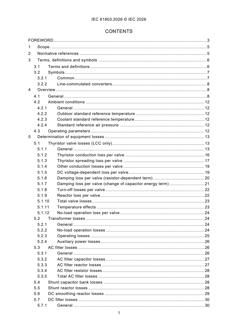
CONTENTS
FOREWORD . 3
1 Scope . 5
2 Normative references . 5
3 Terms, definitions and symbols . 6
3.1 Terms and definitions. 6
3.2 Symbols . 7
3.2.1 Common . 7
3.2.2 Line-commutated converters . 8
4 Overview . 8
4.1 General . 8
4.2 Ambient conditions . 12
4.2.1 General . 12
4.2.2 Outdoor standard reference temperature . 12
4.2.3 Coolant standard reference temperature . 12
4.2.4 Standard reference air pressure . 12
4.3 Operating parameters . 12
5 Determination of equipment losses . 13
5.1 Thyristor valve losses (LCC only) . 13
5.1.1 General . 13
5.1.2 Thyristor conduction loss per valve . 16
5.1.3 Thyristor spreading loss per valve . 17
5.1.4 Other conduction losses per valve . 19
5.1.5 DC voltage-dependent loss per valve. 19
5.1.6 Damping loss per valve (resistor-dependent term) . 20
5.1.7 Damping loss per valve (change of capacitor energy term) . 21
5.1.8 Turn-off losses per valve . 22
5.1.9 Reactor loss per valve . 22
5.1.10 Total valve losses . 23
5.1.11 Temperature effects . 23
5.1.12 No-load operation loss per valve . 24
5.2 Transformer losses . 24
5.2.1 General . 24
5.2.2 No-load operation losses . 24
5.2.3 Operating losses . 25
5.2.4 Auxiliary power losses . 26
5.3 AC filter losses . 26
5.3.1 General . 26
5.3.2 AC filter capacitor losses . 27
5.3.3 AC filter reactor losses . 27
5.3.4 AC filter resistor losses . 28
5.3.5 Total AC filter losses . 28
5.4 Shunt capacitor bank losses . 28
5.5 Shunt reactor losses . 28
5.6 DC smoothing reactor losses . 29
5.7 DC filter losses . 30
5.7.1 General . 30
5.7.2 DC filter capacitor losses . 30
5.7.3 DC filter reactor losses . 31
5.7.4 DC filter resistor losses . 31
5.7.5 Total DC filter losses . 31
5.8 Auxiliaries and station service losses . 31
5.9 Series filter losses . 32
5.10 Phase reactor losses (VSC only) . 33
5.11 Valve reactor losses (VSC only) . 35
5.12 Other equipment losses . 35
Annex A (informative) Calculation of harmonic currents and voltages (LCC only) . 36
A.1 Harmonic currents in converter transformers . 36
A.2 Harmonic currents in the AC filters . 36
A.3 Harmonic voltages on the DC side . 37
A.4 DC side harmonic currents in the smoothing reactor . 37
Annex B (informative) Typical station losses . 38
Annex C (informative) HVDC converter station loss evaluation – An illustration . 39
C.1 General . 39
C.2 Loss evaluation under various cases. 40
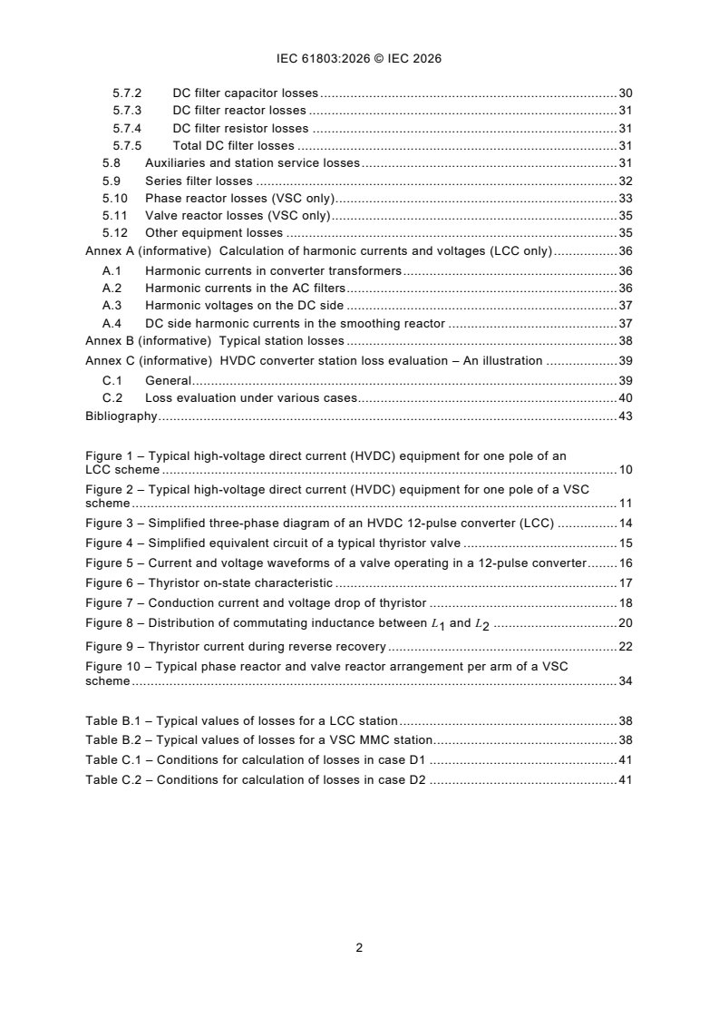
Bibliography . 43
Figure 1 – Typical high-voltage direct current (HVDC) equipment for one pole of an
LCC scheme . 10
Figure 2 – Typical high-voltage direct current (HVDC) equipment for one pole of a VSC
scheme . 11
Figure 3 – Simplified three-phase diagram of an HVDC 12-pulse converter (LCC) . 14
Figure 4 – Simplified equivalent circuit of a typical thyristor valve . 15
Figure 5 – Current and voltage waveforms of a valve operating in a 12-pulse converter . 16
Figure 6 – Thyristor on-state characteristic . 17
Figure 7 – Conduction current and voltage drop of thyristor . 18
Figure 8 – Distribution of commutating inductance between L and L . 20
1 2
Figure 9 – Thyristor current during reverse recovery . 22
Figure 10 – Typical phase reactor and valve reactor arrangement per arm of a VSC
scheme . 34
Table B.1 – Typical values of losses for a LCC station . 38
Table B.2 – Typical values of losses for a VSC MMC station . 38
Table C.1 – Conditions for calculation of losses in case D1 . 41
Table C.2 – Conditions for calculation of losses in case D2 . 41
INTERNATIONAL ELECTROTECHNICAL COMMISSION
____________
Determination of power losses in high-voltage
direct current (HVDC) converter stations
FOREWORD
1) The International Electrotechnical Commission (IEC) is a worldwide organization for standardization comprising
all national electrotechnical committees (IEC National Committees). The object of IEC is to promote international
co-operation on all questions concerning standardization in the electrical and electronic fields. To this end and
in addition to other activities, IEC publishes International Standards, Technical Specifications, Technical Reports,
Publicly Available Specifications (PAS) and Guides (hereafter referred to as "IEC Publication(s)"). Their
preparation is entrusted to technical committees; any IEC National Committee interested in the subject dealt with
may participate in this preparatory work. International, governmental and non-governmental organizations liaising
with the IEC also participate in this preparation. IEC collaborates closely with the International Organization for
Standardization (ISO) in accordance with conditions determined by agreement between the two organizations.
2) The formal decisions or agreements of IEC on technical matters express, as nearly as possible, an international
consensus of opinion on the relevant subjects since each technical committee has representation from all
interested IEC National Committees.
3) IEC Publications have the form of recommendations for international use and are accepted by IEC National
Committees in that sense. While all reasonable efforts are made to ensure that the technical content of IEC
Publications is accurate, IEC cannot be held responsible for the way in which they are used or for any
misinterpretation by any end user.
4) In order to promote international uniformity, IEC National Committees undertake to apply IEC Publications
transparently to the maximum extent possible in their national and regional publications. Any divergence between
any IEC Publication and the corresponding national or regional publication shall be clearly indicated in the latter.
5) IEC itself does not provide any attestation of conformity. Independent certification bodies provide conformity
assessment services and, in some areas, access to IEC marks of conformity. IEC is not responsible for any
services carried out by independent certification bodies.
6) All users should ensure that they have the latest edition of this publication.
7) No liability shall attach to IEC or its directors, employees, servants or agents including individual experts and
members of its technical committees and IEC National Committees for any personal injury, property damage or
other damage of any nature whatsoever, whether direct or indirect, or for costs (including legal fees) and
expenses arising out of the publication, use of, or reliance upon, this IEC Publication or any other IEC
Publications.
8) Attention is drawn to the Normative references cited in this publication. Use of the referenced publications is
indispensable for the correct application of this publication.
9) IEC draws attention to the possibility that the implementation of this document may involve the use of (a)
patent(s). IEC takes no position concerning the evidence, validity or applicability of any claimed patent rights in
respect thereof. As of the date of publication of this document, IEC had not received notice of (a) patent(s), which
may be required to implement this document. However, implementers are cautioned that this may not represent
the latest information, which may be obtained from the patent database available at https://patents.iec.ch. IEC
shall not be held responsible for identifying any or all such patent rights.
IEC 61803 has been prepared by subcommittee 22F: Power electronics for electrical
transmission and distribution systems, of IEC technical committee 22: Power electronic systems
and equipment. It is an International Standard.
This third edition cancels and replaces the second edition published in 2020. This edition
constitutes a technical revision.
This edition includes the following significant technical changes with respect to the previous
edition:
a) HVDC stations with voltage-sourced converters (VSC) technology have been included;
b) to facilitate the application of this document and to ensure its quality remains consistent,
5.1.8 and 5.8 have been reviewed, taking into consideration that the present thyristor
production technology provides considerably less thyristor parameters dispersion
comparing with the situation in 1999 when the first edition of IEC 61803 was developed;
therefore, the production records of thyristors can be used for the power losses calculation;
c) the calculation of the total station load losses (cases D1 and D2 in Annex C) has been
corrected.
The text of this International Standard is based on the following documents:
Draft Report on voting
22F/860/FDIS 22F/868/RVD
Full information on the voting for its approval can be found in the report on voting indicated in
the above table.
The language used for the development of this International Standard is English.
This document was drafted in accordance with ISO/IEC Directives, Part 2, and developed in
accordance with ISO/IEC Directives, Part 1 and ISO/IEC Directives, IEC Supplement, available
at www.iec.ch/members_experts/refdocs. The main document types developed by IEC are
described in greater detail at www.iec.ch/publications.
The committee has decided that the contents of this document will remain unchanged until the
stability date indicated on the IEC website under webstore.iec.ch in the data related to the
specific document. At this date, the document will be
– reconfirmed,
– withdrawn, or
– revised.
1 Scope
This document applies to all high-voltage direct current (HVDC) converter stations with line-
commutated converters (LCC) as well with voltage-sourced converters (VSC) used for power
exchange (power transmission or back-to-back installation) in utility systems. For line-
commutated converters (LCC), this document presumes the use of 12-pulse thyristor converters
but can, with due care, also be used for 6-pulse thyristor converters.
Where VSC is referred to in this document, it is assumed to be of the MMC-type or similar, with
very low harmonic generation. It is important to treat other types of VSC as appropriate.
In some applications, synchronous compensators, static var compensators (SVC), or static
synchronous compensator (STATCOM) are connected to the AC bus of the HVDC converter
station. The loss determination procedures for such equipment are not included in this
document.
This document presents a set of standard procedures for determining the total losses of an
HVDC converter station, except for VSC valves which are covered by the IEC 62751 series.
The procedures cover all parts, except as noted above, and address no-load operation and
operating losses together with their methods of calculation which use, wherever possible,
measured parameters.
Converter station designs employing novel components or circuit configurations compared to
the typical design assumed in this document, or designs equipped with unusual auxiliary circuits
that can affect the losses, are assessed on their own merits.
2 Normative references
The following documents are referred to in the text in such a way that some or all of their content
constitutes requirements of this document. For dated references, only the edition cited applies.
For undated references, the latest edition of the referenced document (including any
amendments) applies.
IEC 60076-1, Power transformers - Part 1: General
IEC 60076-6, Power transformers - Part 6: Reactors
IEC 60633, High-voltage direct current (HVDC) transmission - Vocabulary
IEC 60700-1:2015, Thyristor valves for high voltage direct current (HVDC) power transmission -
Part 1: Electrical testing
IEC 60700-1:2015/AMD1:2021
IEC 60871-1, Shunt capacitors for a.c. power systems having a rated voltage above 1 000 V -
Part 1: General
IEC 62747, Terminology for voltage-sourced converters (VSC) for high-voltage direct current
(HVDC) systems
3 Terms, definitions and symbols
For the purposes of this document, the terms and definition given in IEC 60633, IEC 62747 and
the following apply.
ISO and IEC maintain terminological databases for use in standardization at the following
addresses:
– IEC Electropedia: available at http://www.electropedia.org/
– ISO Online browsing platform: available at http://www.iso.org/obp
3.1 Terms and definitions
3.1.1
auxiliary losses
electric power required to feed the converter station auxiliary loads
Note 1 to entry: The auxiliary losses depend on the number of converter units used and whether the station is in
no-load operation or carrying load, in which case the auxiliary losses depend on the load level.
3.1.2
equipment no-load operation losses
losses produced in an item of equipment with the converter station energised but with the
converters blocked and all station service loads and auxiliary equipment connected as required
for immediate pick-up of load to specified minimum power
3.1.3
load level
set of AC system and converter operating conditions at which the converter station is operating
Note 1 to entry: For LCC schemes, the load level is defined by the direct current, direct voltage, firing angle, AC
system voltage and converter transformer tap-changer position.
Note 2 to entry: For VSC schemes, the load level is defined by the direct current, direct voltage, AC system voltage,
interface transformer tap-changer position (where appropriate), converter AC voltage, converter AC current and the
phase angle between converter AC voltage and current.
3.1.4
equipment operating losses
losses produced in an item of equipment at a given load level with the converter station
energised and the converters operating
3.1.5
rated load
load corresponding to operation at nominal values of the operating conditions defined in 3.1.3
Note 1 to entry: The AC system shall be assumed to be at nominal frequency, and its 3-phase voltages are nominal
and balanced. The position of the tap-changer of the converter/interface transformer and the number of AC filters
and shunt reactive elements, if any connected, shall be consistent with operation at rated load, coincident with
nominal conditions.
3.1.6
total station no-load operation losses
sum of all equipment no-load operation losses (3.1.2) and corresponding auxiliary losses (3.1.1)
3.1.7
total station operating losses
sum of all equipment operating losses (3.1.4) and corresponding auxiliary losses (3.1.1) at a
particular load level
Note 1 to entry: An illustrative example using total station operating losses and corresponding loss evaluation is
given in Annex C, case D1.
3.1.8
total station load losses
difference between total station operating losses (3.1.7) and total station no-load operation
losses (3.1.6)
Note 1 to entry: Such calculated total station load losses are considered as being quantitatively equivalent to load
losses as in conventional AC substation practice.
Note 2 to entry: It is recognized that some purchasers evaluate total station no-load operation losses (3.1.6) and
total station load losses individually instead of the evaluating total station operating losses (3.1.7).
Note 3 to entry: An illustrative example to derive load losses, equivalent load losses and corresponding loss
evaluation is given in Annex C, case D2.
3.1.9
station essential auxiliary load
load whose failure affects the conversion capability of the HVDC converter station (e.g. valve
cooling), as well as load that remains working in case of complete loss of AC power supply (e.g.
battery chargers, operating mechanisms)
3.2 Symbols
3.2.1 Common
f AC system frequency, in hertz (Hz)
I direct current, in amperes (A)
d
I harmonic RMS current of order n, in amperes (A)
n
n harmonic order
P power loss in an item of equipment, in watts (W)
Q quality factor of a reactor at harmonic order n
n
R resistance value, in ohms (Ω)
U direct voltage, in volts (V)
d
U harmonic RMS voltage of order n, in volts (V)
n
X inductive reactance at harmonic order n, in ohms (Ω)
n
3.2.2 Line-commutated converters
α (trigger/firing) delay angle, in radians (rad)
γ extinction angle, in radians (rad)
µ overlap angle, in radians (rad)
L inductance, in henrys (H), referred to the valve winding, between the commutating
voltage source and the point of common coupling between star- and delta-connected
windings; L shall include any external inductance between the transformer line-
winding terminals and the point of connection of the AC harmonic filters
L inductance, in henrys (H), referred to the valve winding, between the point of common
coupling between star- and delta-connected windings; the valve L shall include the
saturated inductance of the valve reactors
m electromagnetic notch coupling factor, m = L /(L + L )
1 1 2
N number of series-connected thyristors per valve
t
U RMS value of the phase-to-phase no-load voltage on the valve side of the converter
vo
transformer excluding harmonics, in volts (V)
4 Overview
4.1 General
It is important for suppliers to know in detail how and where losses are generated, since this
affects component and equipment ratings. Purchasers are interested in a verifiable loss figure
which allows equitable bid comparison and in a procedure which can objectively verify the
guaranteed performance requirements of the supplier after delivery. The main purpose of this
document is to serve the purchasers this specific interest.
As a general principle, it would be desirable to determine the efficiency of an HVDC converter
station by a direct measurement of its energy losses. However, attempts to determine the
station losses by subtracting the measured output power from the measured input power should
recognize that such measurements have an inherent inaccuracy, especially if performed at high
voltage. The losses of an HVDC converter station at full load are generally less than 1 % of the
transmitted power. Therefore, the loss measured as a small difference between two large
quantities is not likely to be a sufficiently accurate indication of the actual losses.
In some special circumstances, it can be possible, for example, to arrange a temporary test
connection in which two converters are operated from the same AC source and also connected
together via their DC terminals. In this connection, the power drawn from the AC source equals
the losses in the circuit though in most cases this does not represent a normal operating design
mode. However, the AC source shall also provide var support and commutating voltage to the
two converters. Once again, there are practical measurement difficulties, and it is still important
that the losses are recalculated/corrected for nominal parameters and ambient/operating
conditions.
In order to avoid the problems described above since these practical measurements are
unreliable and also will depend on the type of HVDC solution, it is recommended to use this
document which standardizes a method of calculating the HVDC converter station losses by
summing the losses calculated for each item of equipment. The standardized calculation
method will help the purchaser to meaningfully compare the competing bids. It will also allow
an easy generation of performance curves for the wide range of operating conditions in which
the performance has to be known. In the absence of an inexpensive experimental method which
could be employed for an objective verification of losses during type tests, the calculation
method is the next best alternative as it uses, wherever possible, experimental data obtained
from measurements on individual equipment and components under conditions equivalent to
those encountered in real operation.
Typical high-voltage direct current (HVDC) equipment for one pole of an LCC HVDC substation
is shown in Figure 1 and for one pole of a VSC HVDC substation in Figure 2. The calculation of
harmonic currents and voltages in HVDC equipment for line-commutated converter stations is
described in Annex A.
Key
1 AC switchyard 9 DC smoothing reactor
2 shunt reactor bank 10 voltage divider
3 shunt capacitor bank 11 PLC filter
4 AC filter bank 12 DC filter
5 capacitor voltage transformer 13 DC current measuring device
6 PLC filter 14 pole line
7 converter transformer 15 ground electrode
8 valve hall
Figure 1 – Typical high-voltage direct current (HVDC) equipment
for one pole of an LCC scheme
Key
1 circuit breaker 9 VSC unit
2 pre-Insertion resistor 10 VSC DC capacitor
3 line side harmonic filter 11 DC harmonic filter
4 line side high frequency filter 12 dynamic braking system
5 interface transformer 13 neutral point grounding branch
6 converter side harmonic filter 14 DC reactor
7 + 8 converter side high frequency filter 15 DC cable or overhead transmission line
8 phase reactor
a
In some designs of VSC based on VSC switch type valves, the harmonic filters may not be required.
b
In some designs of VSC, the phase reactor may fulfill part of the function of the converter-side high frequency
filter.
c
In some VSC topologies, each valve of the VSC unit may include a "valve reactor", which can be built into the
valve or provided as a separate component.
d
In some designs of VSC, the VSC DC capacitor may be partly or entirely distributed amongst the three phase
units of the VSC Unit, where it is referred to as the DC submodule capacitors.
e
The philosophy and location of the neutral point grounding branch can be different depending on the design of
the VSC unit.
f
In some designs of VSC, the interface transformer can fulfill part of the function of the line-side high frequency
filter.
g
Optional.
h
Optional, if phase reactors or valve reactors are located on the DC side of the converter.
Figure 2 – Typical high-voltage direct current (HVDC) equipment
for one pole of a VSC scheme
Compared with LCCs, VSCs for HVDC systems generate a much less distorted AC side current
waveform. Depending on the converter topology and the control methods employed for VSC,
the network side voltage generated by the converter can approach a clean fundamental
frequency sinusoid. The VSC converter can be considered as a harmonic voltage source behind
an internal impedance, rather than a current source as for LCCs, as it is the generated harmonic
voltage which remains independent of load. The harmonic levels can be extremely low
compared to LCCs, but due to the adopted switching regime have a significant frequency range
much higher than for LCCs, and can contain inter-harmonics, which are a result of the control
strategy adopted. Refer to the IEC TR 62001-5 for harmonics generation of VSC converters.
NOTE In this document, where the term "harmonic" is used for VSC converters, it is considered to mean the
"harmonic group" according to IEC 61000-4-7, which includes the integer harmonic and the spectral bins from h – 0,5
to h + 0,5, instead of "harmonic number n".
It is important to note that the power loss in each item of equipment will depend on the ambient
conditions under which it operates, as well as on the operating conditions or duty cycles to
which it is subjected. Therefore, the ambient and operating conditions shall be defined for each
item of equipment, based on the ambient and operating conditions of the entire HVDC converter
station.
It is recognized that, for AC and DC side filter equipment, the specified notional requirements
do not represent the actual losses to be expected in service; however, the simplified approach
specified in this document is considered acceptable to estimate losses and compare different
bids.
4.2 Ambient conditions
4.2.1 General
A set of standard reference ambient conditions shall be used for determining the power losses
in HVDC converter stations.
4.2.2 Outdoor standard reference temperature
An outdoor ambient dry bulb temperature of 20 °C shall be used as the standard reference
temperature for determining the total converter station losses. The corresponding valve hall
temperature can be defined by the supplier if necessary. The equivalent wet-bulb temperature
(where necessary) shall be defined by the purchaser.
If not defined, the wet-bulb temperature is recommended to be 14 °C, which corresponds to
approximately 50 % RH at 20 °C dry bulb temperature.
4.2.3 Coolant standard reference temperature
Where forced cooling is used for equipment, the flow rate and temperature of the coolant can
influence the temperature rise and associated losses of that equipment. Therefore, the coolant
temperatures and flow rates established by the purchaser and the supplier shall be used as a
basis for determining the losses.
4.2.4 Standard reference air pressure
The reference air pressure to be used for the evaluation of total converter station power losses
shall be the standard atmospheric pressure (101,3 kPa) corrected to the altitude of the
installation in question when station is located above 1 000 m above sea level.
4.3 Operating parameters
The losses of an HVDC converter station depend on its operating parameters.
The losses of HVDC converter stations are classified into two categories, referred to as
operating losses (3.1.4 and 3.1.7) and no-load operation losses (3.1.2 and 3.1.6).
The operating losses and auxiliary losses are affected by the load level of the station because
the numbers of certain types of energised equipment (for example harmonic filters and cooling
equipment) can depend upon the load level and because losses in individual items of equipment
themselves vary with the load level.
HVDC converter station losses shall be determined for nominal (balanced) AC system voltage
and frequency, symmetrical impedances of the transformer (between phases, and for LCC
schemes, between the star and delta-connected bridges) and, for LCC schemes, symmetrical
firing angles. The transformer tap-changer shall be assumed to be in the position corresponding
to nominal AC system voltage or as decided by the control system for the defined operating
condition.
The operating losses shall be determined for the load levels specified by the purchaser, or at
rated load if no such conditions are specified. For each load level, the converter operating
conditions defined in 3.1.3, shunt compensation and harmonic filtering equipment shall be
consistent with the respective load level and other specified performance requirements,
relating, for example, to harmonic distortion and minimum reactive power exchange with the
connected ac network. Cooling and other auxiliary equipment, as appropriate to the standard
reference temperature (see 4.2.2 and 4.2.3), shall be assumed to be connected to support the
respective load level. Unless specifically specified, reactive power shall be assumed zero for a
VSC station.
For the no-load operation mode, transformers shall be energised and the converters blocked.
All filters and reactive power compensation equipment shall be assumed to be disconnected
except for those which are required to sustain operation at zero load in order, for example, to
meet the specified reactive power requirements. Station service loads and auxiliary equipment
(e.g. cooling-water pumps) shall be assumed to be connected as required for immediate pick-
up of load for the converter station (without waiting for tap changer movement) to specified
minimum power.
NOTE For some MMC VSC valves, it can be impracticable to keep the converter blocked with AC circuit breaker
closed for a while, due to a need for balancing the submodule capacitor voltages. The operating state generally
known as "idling operating state" will also have an additional contribution of valve losses. However, for the purpose
of guaranteeing loss calculation, it is sufficient to compare losses for no-load operation losses as defined in 3.1.2 at
zero active and reactive power.
5 Determination of equipment losses
5.1 Thyristor valve losses (LCC only)
5.1.1 General
The loss production mechanisms applicable when the valves are blocked (no-load operation
losses) are different from those applicable in normal operation (operating losses). Operating
losses are dealt with in 5.1.2 to 5.1.11, and no-load operation losses are dealt with in 5.1.12.
Auxiliary losses are dealt with in 5.8.
A simplified three-phase diagram of an HVDC 12-pulse converter is shown in Figure 3.
Individual valves are marked in the order of their conduction sequence.
Key
A high-voltage DC terminal
B upper bridge
C lower bridge
D low voltage DC terminal
Figure 3 – Simplified three-phase diagram of an HVDC 12-pulse converter (LCC)
A simplified equivalent circuit of a typical valve is shown in Figure 4, where symbol "th"
combines the effects of N thyristors connected in series in the valve. C and R are the
t AC AC
corresponding combined values of R-C damping circuits used for voltage sharing and
overvoltage suppression. R represents DC grading resistors and other resistive components
DC
which incur loss when the valve blocks voltage; it also includes the effects of the thyristor
leakage current (see 5.1.5 and 5.1.12). C includes both stray capacitances and surge
s
distribution capacitors (if used). L represents saturable reactors used to limit the di/dt stresses
s
to safe values and to improve the distribution of fast rising voltages. R represents the
s
resistances of the current conducting components of the valve such as the busbars, contact
resistances, resistance of the windings of the saturable reactors, etc. Power losses in the valve
surge arrester (not shown) shall be neglected.
Key
1 control and monitoring
Figure 4 – Simplified equivalent circuit of a typical thyristor valve
Figure 5 shows, as an example, current and voltage waveforms of valve 1 (according to Figure 3)
operating in rectifier – Figure 5 a) – and inverter – Figure 5 b) – modes. In the example shown,
the firing instants of the valves of the upper bridge are delayed by 30° with respect to the valves
of the lower bridge due to the phase shift between the two secondaries. For each valve, the
length of the conduction intervals is about 130° (2π/3 + μ). During commutations, the valve
current is assumed, for this document, to be changing linearly whereas, in reality, the valve
currents follow portions of sine waves. This simplification has negligible effect on the resulting
losses, while the trapezoidal waveform significantly simplifies the calculations. The voltage
blocked by the valve shows notches caused by commutations between individual valves.
α = 20° µ = 10°
a) Rectifier operation
γ = 20° µ = 10°
b) Inverter operation
NOTE Commutation overshoots are not shown.
Figure 5 – Current and voltage waveforms of a valve operating in a 12-pulse converter
5.1.2 Thyristor conduction loss per valve
A typical thyristor on-state characteristic is shown in Figure 6. Thyristor conduction loss
component is the product of the conduction current i(t) – Figure 7 a) – and the corresponding
ideal on-state voltage as shown in Figure 6.
Figure 6 – Thyristor on-state characteristic
Formula P shall be used provided that the DC bridge current is well smoothed. In the event
V1a
that the root sum square value of the DC side harmonic currents, determined in accordance
with Clause A.4, exceeds 5 % of the DC component, formula P shall be used instead.
V1b
NI× 2π− µ
td
P U+ RI××
V1a 0 0 d
32π
n=48
N ××I U N × R 2π − µ
td 0 t 0 22
P= ++II
V1b d ∑ n
33 2π
n=12
where
U is the current-independent component of the on-state voltage of the average thyristor (see
note below), in volts;
R is the slope resistance of the on-state characteristic of the average thyristor (see note
below), in ohms;
th
I is the calculated RMS value of the n harmonic current in the bridge DC connection
n
according to Clause A.4, in amperes.
NOTE U and R (see Figure 6) are determined from the fully spread on-state voltage measured at the appropriate
0 0
current and junction temperature. The average value of U and R is obtained from production records of the
0 0
thyristors. The temperature dependence of U and R is established from type tests or routine tests on a statistically
0 0
significant number of the thyristors employed, and is used, where necessary, to correct U and R to the appropriate
0 0
service junction temperature. If parallel connection of p thyristors is employed, the appropriate 100 % current is the
nominal DC bridge current divided by p. The calculated result is then multiplied by p.
5.1.3 Thyristor spreading loss per valve
This loss component is an additional conduction loss of the thyristors arising from the delay in
establishing full conduction of the silicon after the thyristor has been turned on. The additional
loss is the product of the current and the voltage by which the thyristor voltage exceeds the
ideal thyristor on-state voltage drop – see the hatched area in Figure 7 b).
=
a) Conduction current
b) Voltage drop across an ideal thyristor A or a real thyristor B
In Figure 7 b), the ideal thyristor A is a thyristor with a conduction characteristic determined by U and R (as per
0 0
Figure 6). The real thyristor B is a thyristor which displays the spreading effect.
Figure 7 – Conduction current and voltage drop of thyristor
t1
P = N××f u t− u t ×i t dt
( ) ( ) ( )
V2 t B A
∫
where
t is the length of the conduction interval, in seconds, which is given by:
π + µ
t =
2πf
u (t) is the instantaneous on-state voltage, in volts, of a thyristor whose fully spread on-state
B
voltage is typical for the thyristors used; the instantaneous on-state voltage shall be
determined for the appropriate junction temperature measured with a trapezoidal current
pulse exhibiting the correct amplitude and commutation overlap periods (see Figure 6
and Figure 7);
u (t) is the calculated instantaneous on-state voltage of the average thyristor at the same
A
junction temperature for the same current pulse but with the conducting area fully
established throughout the conduction, as derived from its on-state characteristic
represented by U and R only (see Figure 6);
0 0
i(t) is the instantaneous current in the thyristor, in amperes.
Instantaneous on-state voltage data, including the effects of spreading, are usually not available
from production records. Measurements of typical thyristor on-state voltage, including
...
IEC 61803 ®
Edition 3.0 2026-05
INTERNATIONAL
STANDARD
COMMENTED VERSION
Determination of power losses in high-voltage direct current (HVDC) converter
stations
ICS 29.200 ISBN 978-2-8327-1267-2
All rights reserved. Unless otherwise specified, no part of this publication may be reproduced or utilized in any form or
by any means, electronic or mechanical, including photocopying and microfilm, without permission in writing from either
IEC or IEC's member National Committee in the country of the requester. If you have any questions about IEC copyright
or have an enquiry about obtaining additional rights to this publication, please contact the address below or your local
IEC member National Committee for further information.
IEC Secretariat Tel.: +41 22 919 02 11
3, rue de Varembé info@iec.ch
CH-1211 Geneva 20 www.iec.ch
Switzerland
About the IEC
The International Electrotechnical Commission (IEC) is the leading global organization that prepares and publishes
International Standards for all electrical, electronic and related technologies.
About IEC publications
The technical content of IEC publications is kept under constant review by the IEC. Please make sure that you have the
latest edition, a corrigendum or an amendment might have been published.
IEC publications search - IEC Products & Services Portal - products.iec.ch
webstore.iec.ch/advsearchform Discover our powerful search engine and read freely all the
The advanced search enables to find IEC publications by a publications previews, graphical symbols and the glossary.
variety of criteria (reference number, text, technical With a subscription you will always have access to up to date
committee, …). It also gives information on projects, content tailored to your needs.
replaced and withdrawn publications.
Electropedia - www.electropedia.org
The world's leading online dictionary on electrotechnology,
IEC Just Published - webstore.iec.ch/justpublished
Stay up to date on all new IEC publications. Just Published containing more than 22 500 terminological entries in English
details all new publications released. Available online and and French, with equivalent terms in 25 additional languages.
once a month by email. Also known as the International Electrotechnical Vocabulary
(IEV) online.
IEC Customer Service Centre - webstore.iec.ch/csc
If you wish to give us your feedback on this publication or
need further assistance, please contact the Customer
Service Centre: sales@iec.ch.
CONTENTS
FOREWORD . 3
1 Scope . 5
2 Normative references . 5
3 Terms, definitions and symbols . 6
3.1 Terms and definitions. 6
3.2 Symbols . 7
3.2.1 Common . 7
3.2.2 Line-commutated converters . 7
4 Overview . 8
4.1 General . 8
4.2 Ambient conditions . 11
4.2.1 General . 11
4.2.2 Outdoor standard reference temperature . 11
4.2.3 Coolant standard reference temperature . 11
4.2.4 Standard reference air pressure . 11
4.3 Operating parameters . 11
5 Determination of equipment losses . 12
5.1 Thyristor valve losses (LCC only) . 12
5.1.1 General . 12
5.1.2 Thyristor conduction loss per valve . 15
5.1.3 Thyristor spreading loss per valve . 16
5.1.4 Other conduction losses per valve . 18
5.1.5 DC voltage-dependent loss per valve. 18
5.1.6 Damping loss per valve (resistor-dependent term) . 19
5.1.7 Damping loss per valve (change of capacitor energy term) . 20
5.1.8 Turn-off losses per valve . 21
5.1.9 Reactor loss per valve . 22
5.1.10 Total valve losses . 22
5.1.11 Temperature effects . 22
5.1.12 No-load operation loss per valve . 23
5.2 Converter Transformer losses . 23
5.2.1 General . 23
5.2.2 No-load operation losses . 24
5.2.3 Operating losses . 24
5.2.4 Auxiliary power losses . 25
5.3 AC filter losses . 25
5.3.1 General . 25
5.3.2 AC filter capacitor losses . 26
5.3.3 AC filter reactor losses . 26
5.3.4 AC filter resistor losses . 27
5.3.5 Total AC filter losses . 27
5.4 Shunt capacitor bank losses . 27
5.5 Shunt reactor losses . 27
5.6 DC smoothing reactor losses . 28
5.7 DC filter losses . 29
5.7.1 General . 29
5.7.2 DC filter capacitor losses . 29
5.7.3 DC filter reactor losses . 30
5.7.4 DC filter resistor losses . 30
5.7.5 Total DC filter losses . 30
5.8 Auxiliaries and station service losses . 30
5.9 Series filter losses . 31
5.10 Phase reactor losses (VSC only) . 32
5.11 Valve reactor losses (VSC only) . 34
5.12 Other equipment losses . 34
Annex A (informative) Calculation of harmonic currents and voltages (LCC only) . 35
A.1 Harmonic currents in converter transformers . 35
A.2 Harmonic currents in the AC filters . 35
A.3 Harmonic voltages on the DC side . 36
A.4 DC side harmonic currents in the smoothing reactor . 36
Annex B (informative) Typical station losses . 37
Annex C (informative) HVDC converter station loss evaluation – An illustration . 38
C.1 General . 38
C.2 Loss evaluation under various cases. 39
Bibliography . 42
List of comments. 43
Figure 1 – Typical high-voltage direct current (HVDC) equipment for one pole of an
LCC scheme . 9
Figure 2 – Typical high-voltage direct current (HVDC) equipment for one pole of a VSC
scheme . 10
Figure 3 – Simplified three-phase diagram of an HVDC 12-pulse converter (LCC) . 13
Figure 4 – Simplified equivalent circuit of a typical thyristor valve . 14
Figure 5 – Current and voltage waveforms of a valve operating in a 12-pulse converter . 15
Figure 6 – Thyristor on-state characteristic . 16
Figure 7 – Conduction current and voltage drop of thyristor . 17
Figure 8 – Distribution of commutating inductance between L and L . 19
1 2
Figure 9 – Thyristor current during reverse recovery . 21
Figure 10 – Typical phase reactor and valve reactor arrangement per arm of a VSC
scheme . 33
Table B.1 – Typical values of losses for a LCC station . 37
Table B.2 – Typical values of losses for a VSC MMC station . 37
Table C.1 – Conditions for calculation of losses in case D1 . 40
Table C.2 – Conditions for calculation of losses in case D2 . 40
INTERNATIONAL ELECTROTECHNICAL COMMISSION
____________
Determination of power losses in high-voltage
direct current (HVDC) converter stations with
line-commutated converters 1
FOREWORD
1) The International Electrotechnical Commission (IEC) is a worldwide organization for standardization comprising
all national electrotechnical committees (IEC National Committees). The object of IEC is to promote international
co-operation on all questions concerning standardization in the electrical and electronic fields. To this end and
in addition to other activities, IEC publishes International Standards, Technical Specifications, Technical Reports,
Publicly Available Specifications (PAS) and Guides (hereafter referred to as "IEC Publication(s)"). Their
preparation is entrusted to technical committees; any IEC National Committee interested in the subject dealt with
may participate in this preparatory work. International, governmental and non-governmental organizations liaising
with the IEC also participate in this preparation. IEC collaborates closely with the International Organization for
Standardization (ISO) in accordance with conditions determined by agreement between the two organizations.
2) The formal decisions or agreements of IEC on technical matters express, as nearly as possible, an international
consensus of opinion on the relevant subjects since each technical committee has representation from all
interested IEC National Committees.
3) IEC Publications have the form of recommendations for international use and are accepted by IEC National
Committees in that sense. While all reasonable efforts are made to ensure that the technical content of IEC
Publications is accurate, IEC cannot be held responsible for the way in which they are used or for any
misinterpretation by any end user.
4) In order to promote international uniformity, IEC National Committees undertake to apply IEC Publications
transparently to the maximum extent possible in their national and regional publications. Any divergence between
any IEC Publication and the corresponding national or regional publication shall be clearly indicated in the latter.
5) IEC itself does not provide any attestation of conformity. Independent certification bodies provide conformity
assessment services and, in some areas, access to IEC marks of conformity. IEC is not responsible for any
services carried out by independent certification bodies.
6) All users should ensure that they have the latest edition of this publication.
7) No liability shall attach to IEC or its directors, employees, servants or agents including individual experts and
members of its technical committees and IEC National Committees for any personal injury, property damage or
other damage of any nature whatsoever, whether direct or indirect, or for costs (including legal fees) and
expenses arising out of the publication, use of, or reliance upon, this IEC Publication or any other IEC
Publications.
8) Attention is drawn to the Normative references cited in this publication. Use of the referenced publications is
indispensable for the correct application of this publication.
9) IEC draws attention to the possibility that the implementation of this document may involve the use of (a)
patent(s). IEC takes no position concerning the evidence, validity or applicability of any claimed patent rights in
respect thereof. As of the date of publication of this document, IEC had not received notice of (a) patent(s), which
may be required to implement this document. However, implementers are cautioned that this may not represent
the latest information, which may be obtained from the patent database available at https://patents.iec.ch. IEC
shall not be held responsible for identifying any or all such patent rights.
This commented version (CMV) of the official standard IEC 61803:2026 edition 3.0 allows the
user to identify the changes made to the previous IEC 61803:2020 edition 2.0. Furthermore,
comments from IEC SC 22F experts are provided to explain the reasons of the most relevant
changes, or to clarify any part of the content.
A vertical bar appears in the margin wherever a change has been made. Additions are in green
text, deletions are in strikethrough red text. Experts' comments are identified by a blue-
background number. Mouse over a number to display a pop-up note with the comment.
This publication contains the CMV and the official standard. The full list of comments is available
at the end of the CMV.
IEC 61803 has been prepared by subcommittee 22F: Power electronics for electrical
transmission and distribution systems, of IEC technical committee 22: Power electronic systems
and equipment. It is an International Standard.
This third edition cancels and replaces the second edition published in 2020. This edition
constitutes a technical revision.
This edition includes the following significant technical changes with respect to the previous
edition:
a) HVDC stations with voltage-sourced converters (VSC) technology have been included;
b) to facilitate the application of this document and to ensure its quality remains consistent,
5.1.8 and 5.8 have been reviewed, taking into consideration that the present thyristor
production technology provides considerably less thyristor parameters dispersion
comparing with the situation in 1999 when the first edition of IEC 61803 was developed;
therefore, the production records of thyristors can be used for the power losses calculation;
c) the calculation of the total station load losses (cases D1 and D2 in Annex C) has been
corrected.
The text of this International Standard is based on the following documents:
Draft Report on voting
22F/860/FDIS 22F/868/RVD
Full information on the voting for its approval can be found in the report on voting indicated in
the above table.
The language used for the development of this International Standard is English.
This document was drafted in accordance with ISO/IEC Directives, Part 2, and developed in
accordance with ISO/IEC Directives, Part 1 and ISO/IEC Directives, IEC Supplement, available
at www.iec.ch/members_experts/refdocs. The main document types developed by IEC are
described in greater detail at www.iec.ch/publications.
The committee has decided that the contents of this document will remain unchanged until the
stability date indicated on the IEC website under webstore.iec.ch in the data related to the
specific document. At this date, the document will be
– reconfirmed,
– withdrawn, or
– revised.
1 Scope
This document applies to all line-commutated high-voltage direct current (HVDC) converter
stations with line-commutated converters (LCC) as well with voltage-sourced converters (VSC)
used for power exchange (power transmission or back-to-back installation) in utility systems.
For line-commutated converters (LCC), this document presumes the use of 12-pulse thyristor
converters but can, with due care, also be used for 6-pulse thyristor converters.
Where VSC is referred to in this document, it is assumed to be of the MMC-type or similar, with
very low harmonic generation. It is important to treat other types of VSC as appropriate. 2
In some applications, synchronous compensators, static var compensators (SVC), or static
synchronous compensator (STATCOM) may be are connected to the AC bus of the HVDC
converter station. The loss determination procedures for such equipment are not included in
this document.
This document presents a set of standard procedures for determining the total losses of an
HVDC converter station, except for VSC valves which are covered by the IEC 62751 series 3.
The procedures cover all parts, except as noted above, and address no-load operation and
operating losses together with their methods of calculation which use, wherever possible,
measured parameters.
Converter station designs employing novel components or circuit configurations compared to
the typical design assumed in this document, or designs equipped with unusual auxiliary circuits
that could can affect the losses, are assessed on their own merits.
2 Normative references
The following documents are referred to in the text in such a way that some or all of their content
constitutes requirements of this document. For dated references, only the edition cited applies.
For undated references, the latest edition of the referenced document (including any
amendments) applies.
IEC 60076-1, Power transformers - Part 1: General
IEC 60076-6, Power transformers - Part 6: Reactors
IEC 60633, High-voltage direct current (HVDC) transmission - Vocabulary
IEC 60700-1:2015, Thyristor valves for high voltage direct current (HVDC) power transmission -
Part 1: Electrical testing
IEC 60700-1:2015/AMD1:2021
IEC 60871-1, Shunt capacitors for a.c. power systems having a rated voltage above 1 000 V -
Part 1: General
IEC 62747, Terminology for voltage-sourced converters (VSC) for high-voltage direct current
(HVDC) systems
3 Terms, definitions and symbols
For the purposes of this document, the terms and definition given in IEC 60633, IEC 62747 and
the following apply.
ISO and IEC maintain terminological databases for use in standardization at the following
addresses:
– IEC Electropedia: available at http://www.electropedia.org/
– ISO Online browsing platform: available at http://www.iso.org/obp
3.1 Terms and definitions
3.1.1
auxiliary losses
electric power required to feed the converter station auxiliary loads
Note 1 to entry: The auxiliary losses depend on the number of converter units used and whether the station is in
no-load operation or carrying load, in which case the auxiliary losses depend on the load level.
3.1.2
equipment no-load operation losses
losses produced in an item of equipment with the converter station energised but with the
converters blocked and all station service loads and auxiliary equipment connected as required
for immediate pick-up of load to specified minimum power
3.1.3
load level
direct current, direct voltage, firing angle, AC voltage, and converter transformer tap-changer
position at which the converter station is operating
set of AC system and converter operating conditions at which the converter station is operating
Note 1 to entry: For LCC schemes, the load level is defined by the direct current, direct voltage, firing angle, AC
system voltage and converter transformer tap-changer position.
Note 2 to entry: For VSC schemes, the load level is defined by the direct current, direct voltage, AC system voltage,
interface transformer tap-changer position (where appropriate), converter AC voltage, converter AC current and the
phase angle between converter AC voltage and current. 4
3.1.4
equipment operating losses
losses produced in an item of equipment at a given load level with the converter station
energised and the converters operating
3.1.5
rated load
load related to operation at nominal values of DC current, DC voltage, AC voltage and converter
firing angle
load corresponding to operation at nominal values of the operating conditions defined in 3.1.3
Note 1 to entry: The AC system shall be assumed to be at nominal frequency, and its 3-phase voltages are nominal
and balanced. The position of the tap-changer of the converter/interface transformer and the number of AC filters
and shunt reactive elements, if any connected, shall be consistent with operation at rated load, coincident with
nominal conditions.
3.1.6
total station no-load operation losses
sum of all equipment no-load operation losses (3.1.2) and corresponding auxiliary losses (3.1.1)
3.1.7
total station operating losses
sum of all equipment operating losses (3.1.4) and corresponding auxiliary losses (3.1.1) at a
particular load level
Note 1 to entry: An illustrative example using total station operating losses and corresponding loss evaluation is
given in Annex C, case D1.
3.1.8
total station load losses
difference between total station operating losses (3.1.7) and total station no-load operation
losses (3.1.6)
Note 1 to entry: Such calculated total station load losses are considered as being quantitatively equivalent to load
losses as in conventional AC substation practice.
Note 2 to entry: It is recognized that some purchasers evaluate total station no-load operation losses (3.1.6) and
total station load losses individually instead of the evaluating total station operating losses (3.1.7).
Note 3 to entry: An illustrative example to derive load losses, equivalent load losses and corresponding loss
evaluation is given in Annex C, case D2.
3.1.9
station essential auxiliary load
load whose failure affects the conversion capability of the HVDC converter station (e.g. valve
cooling), as well as load that shall remain remains working in case of complete loss of AC power
supply (e.g. battery chargers, operating mechanisms)
3.2 Symbols
3.2.1 Common
f AC system frequency, in hertz (Hz)
I direct current, in amperes (A)
d
I harmonic RMS current of order n, in amperes (A)
n
n harmonic order
P power loss in an item of equipment, in watts (W)
Q quality factor of a reactor at harmonic order n
n
R resistance value, in ohms (Ω)
U direct voltage, in volts (V)
d
U harmonic RMS voltage of order n, in volts (V)
n
X inductive reactance at harmonic order n, in ohms (Ω)
n
3.2.2 Line-commutated converters
α (trigger/firing) delay angle, in radians (rad)
γ extinction angle, in radians (rad)
µ overlap angle, in radians (rad)
L inductance, in henrys (H), referred to the valve winding, between the commutating
voltage source and the point of common coupling between star- and delta-connected
windings; L shall include any external inductance between the transformer line-
winding terminals and the point of connection of the AC harmonic filters
L inductance, in henrys (H), referred to the valve winding, between the point of common
coupling between star- and delta-connected windings; the valve L shall include the
saturated inductance of the valve reactors
m electromagnetic notch coupling factor, m = L /(L + L )
1 1 2
N number of series-connected thyristors per valve
t
U RMS value of the phase-to-phase no-load voltage on the valve side of the converter
vo
transformer excluding harmonics, in volts (V)
4 Overview
4.1 General
It is important for suppliers to know in detail how and where losses are generated, since this
affects component and equipment ratings. Purchasers are interested in a verifiable loss figure
which allows equitable bid comparison and in a procedure which can objectively verify the
guaranteed performance requirements of the supplier after delivery. The main purpose of this
document is to serve the purchasers this specific interest.
As a general principle, it would be desirable to determine the efficiency of an HVDC converter
station by a direct measurement of its energy losses. However, attempts to determine the
station losses by subtracting the measured output power from the measured input power should
recognize that such measurements have an inherent inaccuracy, especially if performed at high
voltage. The losses of an HVDC converter station at full load are generally less than 1 % of the
transmitted power. Therefore, the loss measured as a small difference between two large
quantities is not likely to be a sufficiently accurate indication of the actual losses.
In some special circumstances, it may can be possible, for example, to arrange a temporary
test connection in which two converters are operated from the same AC source and also
connected together via their DC terminals. In this connection, the power drawn from the AC
source equals the losses in the circuit though in most cases this does not represent a normal
operating design mode. However, the AC source shall also provide var support and
commutating voltage to the two converters. Once again, there are practical measurement
difficulties, and it is still important that the losses are recalculated/corrected for nominal
parameters and ambient/operating conditions. 5
In order to avoid the problems described above since these practical measurements are
unreliable and also will depend on the type of HVDC solution, it is recommended to use this
document which standardizes a method of calculating the HVDC converter station losses by
summing the losses calculated for each item of equipment. The standardized calculation
method will help the purchaser to meaningfully compare the competing bids. It will also allow
an easy generation of performance curves for the wide range of operating conditions in which
the performance has to be known. In the absence of an inexpensive experimental method which
could be employed for an objective verification of losses during type tests, the calculation
method is the next best alternative as it uses, wherever possible, experimental data obtained
from measurements on individual equipment and components under conditions equivalent to
those encountered in real operation.
Typical high-voltage direct current (HVDC) equipment for one pole of an LCC HVDC substation
is shown in Figure 1 and for one pole of a VSC HVDC substation in Figure 2 6. The calculation
of harmonic currents and voltages in HVDC equipment for line-commutated converter stations
is described in Annex A.
Key
1 AC switchyard 9 DC smoothing reactor
2 shunt reactor bank 10 voltage divider
3 shunt capacitor bank 11 PLC filter
4 AC filter bank 12 DC filter
5 capacitor voltage transformer 13 DC current measuring device
6 PLC filter 14 pole line
7 converter transformer 15 ground electrode
8 valve hall
Figure 1 – Typical high-voltage direct current (HVDC) equipment
for one pole of an LCC scheme
Key
1 circuit breaker 9 VSC unit
2 pre-Insertion resistor 10 VSC DC capacitor
3 line side harmonic filter 11 DC harmonic filter
4 line side high frequency filter 12 dynamic braking system
5 interface transformer 13 neutral point grounding branch
6 converter side harmonic filter 14 DC reactor
7 + 8 converter side high frequency filter 15 DC cable or overhead transmission line
8 phase reactor
a
In some designs of VSC based on VSC switch type valves, the harmonic filters may not be required.
b
In some designs of VSC, the phase reactor may fulfill part of the function of the converter-side high frequency
filter.
c
In some VSC topologies, each valve of the VSC unit may include a "valve reactor", which can be built into the
valve or provided as a separate component.
d
In some designs of VSC, the VSC DC capacitor may be partly or entirely distributed amongst the three phase
units of the VSC Unit, where it is referred to as the DC submodule capacitors.
e
The philosophy and location of the neutral point grounding branch can be different depending on the design of
the VSC unit.
f
In some designs of VSC, the interface transformer can fulfill part of the function of the line-side high frequency
filter.
g
Optional.
h
Optional, if phase reactors or valve reactors are located on the DC side of the converter.
Figure 2 – Typical high-voltage direct current (HVDC) equipment
for one pole of a VSC scheme
Compared with LCCs, VSCs for HVDC systems generate a much less distorted AC side current
waveform. Depending on the converter topology and the control methods employed for VSC,
the network side voltage generated by the converter can approach a clean fundamental
frequency sinusoid. The VSC converter can be considered as a harmonic voltage source behind
an internal impedance, rather than a current source as for LCCs, as it is the generated harmonic
voltage which remains independent of load. The harmonic levels can be extremely low
compared to LCCs, but due to the adopted switching regime have a significant frequency range
much higher than for LCCs, and can contain inter-harmonics, which are a result of the control
strategy adopted. Refer to the IEC TR 62001-5 for harmonics generation of VSC converters. 7
NOTE In this document, where the term "harmonic" is used for VSC converters, it is considered to mean the
"harmonic group" according to IEC 61000-4-7, which includes the integer harmonic and the spectral bins from h – 0,5
to h + 0,5, instead of "harmonic number n".
It is important to note that the power loss in each item of equipment will depend on the ambient
conditions under which it operates, as well as on the operating conditions or duty cycles to
which it is subjected. Therefore, the ambient and operating conditions shall be defined for each
item of equipment, based on the ambient and operating conditions of the entire HVDC converter
station.
It is recognized that, for AC and DC side filter equipment, the specified notional requirements
do not represent the actual losses to be expected in service; however, the simplified approach
specified in this document is considered acceptable to estimate losses and compare different
bids.
4.2 Ambient conditions
4.2.1 General
A set of standard reference ambient conditions shall be used for determining the power losses
in HVDC converter stations.
4.2.2 Outdoor standard reference temperature
An outdoor ambient dry bulb temperature of 20 °C shall be used as the standard reference
temperature for determining the total converter station losses. The corresponding valve hall
temperature may can be defined by the supplier if necessary. The equivalent wet-bulb
temperature (where necessary) shall be defined by the purchaser.
If not defined, the wet-bulb temperature is recommended to be 14 °C, which corresponds to
approximately 50 % RH at 20 °C dry bulb temperature.
4.2.3 Coolant standard reference temperature
Where forced cooling is used for equipment, the flow rate and temperature of the coolant can
influence the temperature rise and associated losses of that equipment. Therefore, the coolant
temperatures and flow rates established by the purchaser and the supplier shall be used as a
basis for determining the losses.
4.2.4 Standard reference air pressure
The reference air pressure to be used for the evaluation of total converter station power losses
shall be the standard atmospheric pressure (101,3 kPa) corrected to the altitude of the
installation in question when station is located above 1 000 m above sea level.
4.3 Operating parameters
The losses of an HVDC converter station depend on its operating parameters.
The losses of HVDC converter stations are classified into two categories, referred to as
operating losses (3.1.4 and 3.1.7) and no-load operation losses (3.1.2 and 3.1.6).
The operating losses and auxiliary losses are affected by the load level of the station because
the numbers of certain types of energised equipment (for example harmonic filters and cooling
equipment) may can depend upon the load level and because losses in individual items of
equipment themselves vary with the load level.
HVDC converter station losses shall be determined for nominal (balanced) AC system voltage
and frequency, symmetrical impedances of the converter transformer (between phases, and for
LCC schemes, between the star and delta-connected bridges) and, for LCC schemes,
symmetrical firing angles. The transformer tap-changer shall be assumed to be in the position
corresponding to nominal AC system voltage or as decided by the control system for the defined
operating condition.
The operating losses shall be determined for the load levels specified by the purchaser, or at
rated load if no such conditions are specified. For each load level, the valve-winding AC voltage,
DC current, converter firing angle, the converter operating conditions defined in 3.1.3, shunt
compensation and harmonic filtering equipment shall be consistent with the respective load
level and other specified performance requirements, relating, for example, to harmonic
distortion and minimum reactive power exchange with the connected ac network. Cooling and
other auxiliary equipment, as appropriate to the standard reference temperature (see 4.2.2
and 4.2.3), shall be assumed to be connected to support the respective load level. Unless
specifically specified, reactive power shall be assumed zero for a VSC station.
For the no-load operation mode, converter transformers shall be energised and the converters
blocked. All filters and reactive power compensation equipment shall be assumed to be
disconnected except for those which are required to sustain operation at zero load in order, for
example, to meet the specified reactive power requirements. Station service loads and auxiliary
equipment (e.g. cooling-water pumps) shall be assumed to be connected as required for
immediate pick-up of load for the converter station (without waiting for tap changer movement)
to specified minimum power.
NOTE For some MMC VSC valves, it can be impracticable to keep the converter blocked with AC circuit breaker
closed for a while, due to a need for balancing the submodule capacitor voltages. The operating state generally
known as "idling operating state" will also have an additional contribution of valve losses. However, for the purpose
of guaranteeing loss calculation, it is sufficient to compare losses for no-load operation losses as defined in 3.1.2 at
zero active and reactive power. 8
5 Determination of equipment losses
5.1 Thyristor valve losses (LCC only)
5.1.1 General
The loss production mechanisms applicable when the valves are blocked (no-load operation
losses) are different from those applicable in normal operation (operating losses). Operating
losses are dealt with in 5.1.2 to 5.1.11, and no-load operation losses are dealt with in 5.1.12.
Auxiliary losses are dealt with in 5.8.
Typical high-voltage direct current (HVDC) equipment for one pole of a HVDC substation is
shown in Figure 1.
A simplified three-phase diagram of an HVDC 12-pulse converter is shown in Figure 3.
Individual valves are marked in the order of their conduction sequence.
Key
A high-voltage DC terminal
B upper bridge
C lower bridge
D low voltage DC terminal
Figure 3 – Simplified three-phase diagram of an HVDC 12-pulse converter (LCC)
A simplified equivalent circuit of a typical valve is shown in Figure 4, where symbol "th"
combines the effects of N thyristors connected in series in the valve. C and R are the
t AC AC
corresponding combined values of R-C damping circuits used for voltage sharing and
overvoltage suppression. R represents DC grading resistors and other resistive components
DC
which incur loss when the valve blocks voltage; it also includes the effects of the thyristor
leakage current (see 5.1.5 and 5.1.12). C includes both stray capacitances and surge
s
distribution capacitors (if used). L represents saturable reactors used to limit the di/dt stresses
s
to safe values and to improve the distribution of fast rising voltages. R represents the
s
resistances of the current conducting components of the valve such as the busbars, contact
resistances, resistance of the windings of the saturable reactors, etc. Power losses in the valve
surge arrester (not shown) shall be neglected.
Key
1 control and monitoring
Figure 4 – Simplified equivalent circuit of a typical thyristor valve
Figure 5 shows, as an example, current and voltage waveforms of valve 1 (according to Figure 3)
operating in rectifier – Figure 5 a) – and inverter – Figure 5 b) – modes. In the example shown,
the firing instants of the valves of the upper bridge are delayed by 30° with respect to the valves
of the lower bridge due to the phase shift between the two secondaries. For each valve, the
length of the conduction intervals is about 130° (2π/3 + μ). During commutations, the valve
current is assumed, for this document, to be changing linearly whereas, in reality, the valve
currents follow portions of sine waves. This simplification has negligible effect on the resulting
losses, while the trapezoidal waveform significantly simplifies the calculations. The voltage
blocked by the valve shows notches caused by commutations between individual valves.
α = 20° µ = 10°
a) Rectifier operation
γ = 20° µ = 10°
b) Inverter operation
NOTE Commutation overshoots are not shown.
Figure 5 – Current and voltage waveforms of a valve operating in a 12-pulse converter
5.1.2 Thyristor conduction loss per valve
A typical thyristor on-state characteristic is shown in Figure 6. Thyristor conduction loss
component is the product of the conduction current i(t) – Figure 7 a) – and the corresponding
ideal on-state voltage as shown in Figure 6.
Figure 6 – Thyristor on-state characteristic
Formula P shall be used provided that the DC bridge current is well smoothed. In the event
V1a
that the root sum square value of the DC side harmonic currents, determined in accordance
with Clause A.4, exceeds 5 % of the DC component, formula P shall be used instead.
V1b
NI× 2π− µ
td
P U+ RI××
V1a 0 0 d
32π
n=48
N ××I U N × R 2π − µ
td 0 t 0 22
P= ++II
V1b d ∑ n
33 2π
n=12
where
U is the current-independent component of the on-state voltage of the average thyristor (see
note below), in volts;
R is the slope resistance of the on-state characteristic of the average thyristor (see note
below), in ohms;
th
I is the calculated RMS value of the n harmonic current in the bridge DC connection
n
according to Clause A.4, in amperes.
NOTE U and R (see Figure 6) are determined from the fully spread on-state voltage measured at the appropriate
0 0
current and junction temperature. The average value of U and R is obtained from production records of the
0 0
thyristors. The temperature dependence of U and R is established from type tests or routine tests on a statistically
0 0
significant number of the thyristors employed, and is used, where necessary, to correct U and R to the appropriate
0 0
service junction temperature. If parallel connection of p thyristors is employed, the appropriate 100 % current is the
nominal DC bridge current divided by p. The calculated result is then multiplied by p.
5.1.3 Thyristor spreading loss per valve
This loss component is an additional conduction loss of the thyristors arising from the delay in
establishing full conduction of the silicon after the thyristor has been turned on. The additional
loss is the product of the current and the voltage by which the thyristor voltage exceeds the
ideal thyristor on-state voltage drop – see the hatched area in Figure 7 b).
=
a) Conduction current
b) Voltage drop across an ideal thyristor A or a real thyristor B
In Figure 7 b), the ideal thyristor A is a thyristor with
...
IEC 61803 ®
Edition 3.0 2026-05
NORME
INTERNATIONALE
Détermination des pertes en puissance dans les stations de conversion en
courant continu à haute tension (CCHT)
ICS 29.200 ISBN 978-2-8327-1202-3
Droits de reproduction réservés. Sauf indication contraire, aucune partie de cette publication ne peut être reproduite ni
utilisée sous quelque forme que ce soit et par aucun procédé, électronique ou mécanique, y compris la photocopie et
les microfilms, sans l'accord écrit de l'IEC ou du Comité national de l'IEC du pays du demandeur. Si vous avez des
questions sur le copyright de l'IEC ou si vous désirez obtenir des droits supplémentaires sur cette publication, utilisez
les coordonnées ci-après ou contactez le Comité national de l'IEC de votre pays de résidence.
IEC Secretariat Tel.: +41 22 919 02 11
3, rue de Varembé info@iec.ch
CH-1211 Geneva 20 www.iec.ch
Switzerland
A propos de l'IEC
La Commission Electrotechnique Internationale (IEC) est la première organisation mondiale qui élabore et publie des
Normes internationales pour tout ce qui a trait à l'électricité, à l'électronique et aux technologies apparentées.
A propos des publications IEC
Le contenu technique des publications IEC est constamment revu. Veuillez vous assurer que vous possédez l’édition la
plus récente, un corrigendum ou amendement peut avoir été publié.
Recherche de publications IEC - IEC Products & Services Portal - products.iec.ch
webstore.iec.ch/advsearchform Découvrez notre puissant moteur de recherche et consultez
La recherche avancée permet de trouver des publications gratuitement tous les aperçus des publications, symboles
IEC en utilisant différents critères (numéro de référence, graphiques et le glossaire. Avec un abonnement, vous aurez
texte, comité d’études, …). Elle donne aussi des toujours accès à un contenu à jour adapté à vos besoins.
informations sur les projets et les publications remplacées
ou retirées. Electropedia - www.electropedia.org
Le premier dictionnaire d'électrotechnologie en ligne au
IEC Just Published - webstore.iec.ch/justpublished monde, avec plus de 22 500 articles terminologiques en
Restez informé sur les nouvelles publications IEC. Just anglais et en français, ainsi que les termes équivalents
dans 25 langues additionnelles. Egalement appelé
Published détaille les nouvelles publications parues.
Disponible en ligne et une fois par mois par email. Vocabulaire Electrotechnique International (IEV) en ligne.
Service Clients - webstore.iec.ch/csc
Si vous désirez nous donner des commentaires sur cette
publication ou si vous avez des questions contactez-
nous: sales@iec.ch.
SOMMAIRE
AVANT-PROPOS . 3
1 Domaine d'application . 5
2 Références normatives . 5
3 Termes, définitions et symboles . 6
3.1 Termes et définitions . 6
3.2 Symboles . 7
3.2.1 Communs . 7
3.2.2 Convertisseurs commutés par le réseau . 8
4 Vue d'ensemble . 8
4.1 Généralités . 8
4.2 Conditions ambiantes . 12
4.2.1 Généralités . 12
4.2.2 Température extérieure de référence normalisée . 12
4.2.3 Température de référence normalisée de l'agent de refroidissement. 12
4.2.4 Pression de l'air de référence normalisée . 12
4.3 Paramètres de fonctionnement . 12
5 Détermination des pertes du matériel . 13
5.1 Pertes de valves à thyristor (LCC uniquement) . 13
5.1.1 Généralités . 13
5.1.2 Pertes de conduction de thyristors par valve . 16
5.1.3 Pertes par étalement dans le thyristor par valve . 17
5.1.4 Autres pertes de conduction par valve . 19
5.1.5 Pertes qui dépendent de la tension continue par valve . 19
5.1.6 Pertes d'amortissement par valve (terme dépendant de la résistance) . 21
5.1.7 Pertes d'amortissement par valve (variation du terme énergie du
condensateur) . 22
5.1.8 Pertes au blocage par valve . 22
5.1.9 Perte d'inductance par valve . 23
5.1.10 Pertes totales de valve . 24
5.1.11 Effets de la température . 24
5.1.12 Pertes en fonctionnement à vide par valve . 24
5.2 Pertes d'un transformateur . 25
5.2.1 Généralités . 25
5.2.2 Pertes en fonctionnement à vide . 25
5.2.3 Pertes en fonctionnement . 25
5.2.4 Pertes en puissance auxiliaire . 27
5.3 Pertes par filtres côté alternatif . 27
5.3.1 Généralités . 27
5.3.2 Pertes au niveau d'un condensateur de filtrage à courant alternatif . 28
5.3.3 Pertes au niveau d'une inductance de filtrage à courant alternatif . 29
5.3.4 Pertes au niveau d'une résistance de filtrage à courant alternatif. 29
5.3.5 Pertes totales au niveau d'un filtre côté alternatif . 29
5.4 Pertes au niveau d'une batterie de condensateurs shunt . 29
5.5 Pertes au niveau d'une bobine d'inductance shunt . 30
5.6 Pertes au niveau d'une bobine d'inductance de lissage en courant continu . 30
5.7 Pertes au niveau d'un filtre côté continu . 32
5.7.1 Généralités . 32
5.7.2 Pertes au niveau d'un condensateur de filtrage à courant continu . 32
5.7.3 Pertes au niveau d'une inductance de filtrage à courant continu . 33
5.7.4 Pertes au niveau d'une résistance de filtrage à courant continu . 33
5.7.5 Pertes totales au niveau d'un filtre côté continu . 33
5.8 Pertes du matériel auxiliaire et de la station en service . 33
5.9 Pertes au niveau d'un filtre en série . 34
5.10 Pertes au niveau de l'inductance de phase (VSC uniquement) . 35
5.11 Pertes au niveau de l'inductance de valve (VSC uniquement) . 37
5.12 Autres pertes au niveau du matériel . 37
Annexe A (informative) Calcul des courants et tensions harmoniques (LCC
uniquement) . 38
A.1 Courants harmoniques dans les transformateurs de conversion . 38
A.2 Courants harmoniques dans les filtres côté alternatif . 38
A.3 Tensions harmoniques sur le côté continu . 39
A.4 Courants harmoniques côté continu dans la bobine d'inductance de lissage . 39
Annexe B (informative) Pertes types de station . 40
Annexe C (informative) Évaluation des pertes d'une station de conversion CCHT –
Illustration . 41
C.1 Généralités . 41
C.2 Évaluation des pertes selon différents cas . 42
Bibliographie . 45
Figure 1 – Matériel type en courant continu à haute tension (CCHT) pour un pôle d'un
système LCC . 10
Figure 2 – Matériel type en courant continu à haute tension (CCHT) pour un pôle d'un
système VSC . 11
Figure 3 – Schéma triphasé simplifié d'un convertisseur à 12 pulsations à CCHT (LCC) . 14
Figure 4 – Circuit équivalent simplifié d'une valve type à thyristors . 15
Figure 5 – Formes d'onde de courant et de tension d'une valve fonctionnant dans un
convertisseur à 12 pulsations . 16
Figure 6 – Courbe caractéristique d'un thyristor à l'état passant . 17
Figure 7 – Courant de conduction et chute de tension d'un thyristor . 18
Figure 8 – Répartition de l'inductance de commutation entre L et L . 20
1 2
Figure 9 – Courant dans le thyristor durant le rétablissement inverse . 22
Figure 10 – Montage type d'une inductance de phase et d'une inductance de valve par
bras d'un système VSC . 36
Tableau B.1 – Valeurs types des pertes pour une station LCC . 40
Tableau B.2 – Valeurs types des pertes pour une station VSC MMC . 40
Tableau C.1 – Conditions de calcul des pertes dans le cas D1 . 43
Tableau C.2 – Conditions de calcul des pertes dans le cas D2 . 44
COMMISSION ÉLECTROTECHNIQUE INTERNATIONALE
____________
Détermination des pertes en puissance dans les stations
de conversion en courant continu à haute tension (CCHT)
AVANT-PROPOS
1) La Commission Électrotechnique Internationale (IEC) est une organisation mondiale de normalisation composée
de l'ensemble des comités électrotechniques nationaux (Comités nationaux de l'IEC). L'IEC a pour objet de
favoriser la coopération internationale pour toutes les questions de normalisation dans les domaines de
l'électricité et de l'électronique. À cet effet, l'IEC – entre autres activités – publie des Normes internationales,
des Spécifications techniques, des Rapports techniques, des Spécifications accessibles au public (PAS) et des
Guides (ci-après dénommés "Publication(s) de l'IEC"). Leur élaboration est confiée à des comités d'études, aux
travaux desquels tout Comité national intéressé par le sujet traité peut participer. Les organisations
internationales, gouvernementales et non gouvernementales, en liaison avec l'IEC, participent également aux
travaux. L'IEC collabore étroitement avec l'Organisation Internationale de Normalisation (ISO), selon des
conditions fixées par accord entre les deux organisations.
2) Les décisions ou accords officiels de l'IEC concernant les questions techniques représentent, dans la mesure du
possible, un accord international sur les sujets étudiés, étant donné que les Comités nationaux de l'IEC intéressés
sont représentés dans chaque comité d'études.
3) Les Publications de l'IEC se présentent sous la forme de recommandations internationales et sont agréées
comme telles par les Comités nationaux de l'IEC. Tous les efforts raisonnables sont entrepris afin que l'IEC
s'assure de l'exactitude du contenu technique de ses publications; l'IEC ne peut pas être tenue responsable de
l'éventuelle mauvaise utilisation ou interprétation qui en est faite par un quelconque utilisateur final.
4) Dans le but d'encourager l'uniformité internationale, les Comités nationaux de l'IEC s'engagent, dans toute la
mesure possible, à appliquer de façon transparente les Publications de l'IEC dans leurs publications nationales
et régionales. Toutes divergences entre toutes Publications de l'IEC et toutes publications nationales ou
régionales correspondantes doivent être indiquées en termes clairs dans ces dernières.
5) L'IEC elle-même ne fournit aucune attestation de conformité. Des organismes de certification indépendants
fournissent des services d'évaluation de conformité et, dans certains secteurs, accèdent aux marques de
conformité de l'IEC. L'IEC n'est responsable d'aucun des services effectués par les organismes de certification
indépendants.
6) Tous les utilisateurs doivent s'assurer qu'ils sont en possession de la dernière édition de cette publication.
7) Aucune responsabilité ne doit être imputée à l'IEC, à ses administrateurs, employés, auxiliaires ou mandataires,
y compris ses experts particuliers et les membres de ses comités d'études et des Comités nationaux de l'IEC,
pour tout préjudice causé en cas de dommages corporels et matériels, ou de tout autre dommage de quelque
nature que ce soit, directe ou indirecte, ou pour supporter les coûts (y compris les frais de justice) et les dépenses
découlant de la publication ou de l'utilisation de cette Publication de l'IEC ou de toute autre Publication de l'IEC,
ou au crédit qui lui est accordé.
8) L'attention est attirée sur les références normatives citées dans cette publication. L'utilisation de publications
référencées est obligatoire pour une application correcte de la présente publication.
9) L'IEC attire l'attention sur le fait que la mise en application du présent document peut entraîner l'utilisation d'un
ou de plusieurs brevets. L'IEC ne prend pas position quant à la preuve, à la validité et à l'applicabilité de tout
droit de brevet revendiqué à cet égard. À la date de publication du présent document, l'IEC n'avait pas reçu
notification qu'un ou plusieurs brevets pouvaient être nécessaires à sa mise en application. Toutefois, il y a lieu
d'avertir les responsables de la mise en application du présent document que des informations plus récentes
sont susceptibles de figurer dans la base de données de brevets, disponible à l'adresse https://patents.iec.ch.
L'IEC ne saurait être tenue pour responsable de ne pas avoir identifié de tels droits de brevets.
L'IEC 61803 a été établie par le sous-comité 22F: Électronique de puissance pour les réseaux
électriques de transport et de distribution, du comité d'études 22 de l'IEC: Systèmes et
équipements électroniques de puissance. Il s'agit d'une Norme internationale.
Cette troisième édition annule et remplace la deuxième édition parue en 2020. Cette édition
constitue une révision technique.
Cette édition inclut les modifications techniques majeures suivantes par rapport à l'édition
précédente:
a) les stations CCHT qui disposent de la technologie des convertisseurs de source de tension
(VSC) ont été incluses;
b) en vue de faciliter l'application de la norme sans en détériorer la qualité, le 5.1.8 et le 5.8
ont été revus en tenant compte du fait que la technologie de production de thyristors actuelle
occasionne considérablement moins de dispersion dans les paramètres des thyristors par
rapport à la situation de 1999, lorsque la première édition de l'IEC 61803 a été élaborée;
ainsi, les données enregistrées de production de thyristors peuvent être utilisées pour les
calculs de pertes en puissance;
c) le calcul des pertes totales d'une station en charge (cas D1 et D2 à l'Annexe C) a été
corrigé.
Le texte de cette Norme internationale est issu des documents suivants:
Projet Rapport de vote
22F/860/FDIS 22F/868/RVD
Le rapport de vote indiqué dans le tableau ci-dessus donne toute information sur le vote ayant
abouti à son approbation.
La langue employée pour l'élaboration de cette Norme internationale est l'anglais.
Ce document a été rédigé selon les Directives ISO/IEC, Partie 2, il a été développé selon les
Directives ISO/IEC, Partie 1 et les Directives ISO/IEC, Supplément IEC, disponibles sous
www.iec.ch/members_experts/refdocs. Les principaux types de documents développés par
l'IEC sont décrits plus en détail sous www.iec.ch/publications.
Le comité a décidé que le contenu de ce document ne sera pas modifié avant la date de stabilité
indiquée sur le site web de l'IEC sous webstore.iec.ch dans les données relatives au document
recherché. À cette date, le document sera
– reconduit,
– supprimé, ou
– révisé.
1 Domaine d'application
Le présent document s'applique à toutes les stations de conversion en courant continu à haute
tension (CCHT) avec convertisseurs commutés par le réseau (LCC, Line-Commutated
Converters) et avec convertisseurs de source de tension (VSC, Voltage-Sourced Converters),
utilisées pour l'échange de puissance (transmission de puissance ou installation dos à dos)
dans des systèmes de distribution d'énergie. Pour les convertisseurs commutés par le réseau
(LCC), le présent document présuppose l'utilisation de convertisseurs à thyristors à
12 pulsations, mais peut également, en prenant les précautions appropriées, s'appliquer à des
convertisseurs à thyristors à 6 pulsations.
Lorsqu'il est fait référence à un VSC dans le présent document, il est admis par hypothèse qu'il
s'agit d'un VSC de type MMC ou similaire, avec une très faible génération d'harmoniques. Il est
important de traiter d'autres types de VSC selon le cas.
Dans certaines applications, des compensateurs synchrones, des compensateurs var statiques
(CVS) ou des compensateurs statiques synchrones (STATCOM) sont connectés au bus en
courant alternatif de la station de conversion en courant continu à haute tension (CCHT). Les
procédures de détermination de pertes pour ce type de matériel ne figurent pas dans le présent
document.
Le présent document décrit un ensemble de procédures types qui permettent de déterminer
l'ensemble des pertes d'une station de conversion CCHT, à l'exception des valves VSC qui sont
couvertes par la série IEC 62751. Les procédures s'appliquent à toutes les pièces, à l'exception
de celles susmentionnées, et prennent en compte les pertes en fonctionnement à vide et les
pertes en fonctionnement ainsi que leurs méthodes de calcul qui utilisent, dans la mesure du
possible, des paramètres mesurés.
Les conceptions de station de conversion qui utilisent des composants ou des configurations
de circuit originaux par rapport à la conception type prise pour hypothèse dans le présent
document, ou des conceptions équipées de circuits auxiliaires inhabituels susceptibles de
modifier les pertes, sont évaluées selon leurs propres mérites.
2 Références normatives
Les documents suivants sont cités dans le texte de sorte qu'ils constituent, pour tout ou partie
de leur contenu, des exigences du présent document. Pour les références datées, seule
l'édition citée s'applique. Pour les références non datées, la dernière édition du document de
référence s'applique (y compris les éventuels amendements).
IEC 60076-1, Transformateurs de puissance - Partie 1: Généralités
IEC 60076-6, Transformateurs de puissance - Partie 6: Bobines d'inductance
IEC 60633, Transport d'énergie en courant continu à haute tension (CCHT) - Vocabulaire
IEC 60700-1:2015, Valves à thyristors pour le transport d'énergie en courant continu à haute
tension (CCHT) - Partie 1: Essais électriques
IEC 60700-1:2015/AMD1:2021
IEC 60871-1, Condensateurs shunt pour réseaux à courant alternatif de tension assignée
supérieure à 1 000 V - Partie 1: Généralités
IEC 62747, Terminologie relative aux convertisseurs de source de tension (VSC) des systèmes
en courant continu à haute tension (CCHT)
3 Termes, définitions et symboles
Pour les besoins du présent document, les termes et définitions de l'IEC 60633 et de
l'IEC 62747 ainsi que les suivants s'appliquent.
L'ISO et l'IEC tiennent à jour des bases de données terminologiques destinées à être utilisées
en normalisation, consultables aux adresses suivantes:
– IEC Electropedia: disponible à l'adresse http://www.electropedia.org/
– ISO Online browsing platform: disponible à l'adresse http://www.iso.org/obp
3.1 Termes et définitions
3.1.1
pertes auxiliaires
puissance électrique exigée pour alimenter les charges auxiliaires des stations de conversion
Note 1 à l'article: Les pertes auxiliaires dépendent du nombre d'unités de conversion utilisées et varient selon que
la station fonctionne à vide ou en charge, auquel cas les pertes auxiliaires dépendent du niveau de charge.
3.1.2
pertes en fonctionnement à vide du matériel
pertes produites dans un élément de matériel tandis que la station de conversion est sous
tension, mais que les convertisseurs sont bloqués et que toutes les charges de station en
service et le matériel auxiliaire sont connectés comme cela est exigé pour la captation
immédiate d'une charge à la puissance minimale spécifiée
3.1.3
niveau de charge
ensemble des conditions de fonctionnement du réseau à courant alternatif et du convertisseur
dans lesquelles la station de conversion fonctionne
Note 1 à l'article: Pour les systèmes LCC, le niveau de charge est défini par le courant continu, la tension continue,
l'angle d'allumage, la tension du réseau à courant alternatif et la position du changeur de prises du transformateur
de conversion.
Note 2 à l'article: Pour les systèmes VSC, le niveau de charge est défini par le courant continu, la tension continue,
la tension du réseau à courant alternatif, la position du changeur de prises du transformateur d'interface (le cas
échéant), la tension alternative du convertisseur, le courant alternatif du convertisseur et l'angle de phase entre la
tension alternative et le courant alternatif du convertisseur.
3.1.4
pertes en fonctionnement du matériel
pertes produites dans un élément de matériel à un niveau de charge donné, tandis que la station
de conversion est sous tension et que les convertisseurs sont en fonctionnement
3.1.5
charge assignée
charge qui correspond au fonctionnement aux valeurs nominales des conditions de
fonctionnement définies au 3.1.3
Note 1 à l'article: Par hypothèse, le réseau à courant alternatif doit être à la fréquence nominale et ses tensions
triphasées sont nominales et équilibrées. La position du changeur de prises du transformateur de
conversion/d'interface et le nombre de filtres à courant alternatif et d'éléments d'inductance shunt éventuellement
connectés doivent être cohérents avec un fonctionnement sous une charge assignée, qui coïncide avec des
conditions nominales.
3.1.6
pertes totales en fonctionnement à vide d'une station
somme de toutes les pertes en fonctionnement à vide du matériel (3.1.2) et des pertes
auxiliaires correspondantes (3.1.1)
3.1.7
pertes totales en fonctionnement d'une station
somme de toutes les pertes en fonctionnement du matériel (3.1.4) et des pertes auxiliaires
correspondantes (3.1.1) à un niveau de charge particulier
Note 1 à l'article: L'Annexe C, cas D1, illustre ceci par un exemple utilisant les pertes totales en
fonctionnement d'une station et l'évaluation des pertes correspondante.
3.1.8
pertes totales d'une station en charge
différence entre les pertes totales en fonctionnement d'une station (3.1.7) et les pertes totales
en fonctionnement à vide d'une station (3.1.6)
Note 1 à l'article: Les pertes totales d'une station en charge ainsi calculées sont considérées comme équivalentes,
sur un plan quantitatif, aux pertes dues à la charge telles que celles de la pratique conventionnelle pour une station
en courant alternatif.
Note 2 à l'article: Il est admis que certains acheteurs évaluent les pertes totales en fonctionnement à vide d'une
station (3.1.6) et les pertes totales d'une station en charge de manière individuelle plutôt que d'évaluer les pertes
totales en fonctionnement d'une station (3.1.7).
Note 3 à l'article: L'Annexe C, cas D2, illustre ceci par un exemple permettant d'extraire les pertes dues à la charge,
les pertes dues à la charge équivalentes et l'évaluation des pertes correspondante.
3.1.9
charge auxiliaire essentielle à la station
charge dont la défaillance compromet la capacité de conversion de la station de conversion
CCHT (par exemple, le refroidissement des valves), ou charge qui continue à fonctionner en
cas de coupure totale de l'alimentation en courant alternatif (par exemple, les chargeurs de
batterie, les mécanismes de fonctionnement)
3.2 Symboles
3.2.1 Communs
f fréquence du réseau à courant alternatif, en hertz (Hz)
I courant continu, en ampères (A)
d
I courant efficace harmonique de rang n, en ampères (A)
n
n rang de l'harmonique
P perte en puissance dans un élément de matériel, en watts (W)
facteur de qualité d'une bobine d'inductance pour un rang d'harmonique n
Q
n
R valeur de la résistance, en ohms (Ω)
U tension continue, en volts (V)
d
U tension efficace harmonique de rang n, en volts (V)
n
X réactance inductive pour un rang d'harmonique n, en ohms (Ω)
n
3.2.2 Convertisseurs commutés par le réseau
α angle de retard (d'amorçage/allumage), en radians (rad)
γ angle d'extinction, en radians (rad)
µ angle d'empiétement, en radians (rad)
L inductance, en henrys (H), se rapportant à l'enroulement de la valve, entre la source
de tension de commutation et le point de couplage commun des enroulements en étoile
et en triangle; L doit inclure toute inductance externe entre les bornes d'enroulement
de ligne du transformateur et le point de connexion des filtres d'harmoniques à courant
alternatif
L inductance, en henrys (H), se rapportant à l'enroulement de la valve, entre le point de
couplage commun des enroulements en étoile et en triangle; la valve L doit inclure
l'inductance saturée des bobines d'inductance de la valve
m facteur de couplage électromagnétique à bande étroite, m = L /(L + L )
1 1 2
N nombre de thyristors connectés en série par valve
t
U valeur efficace de la tension à vide entre phases sur le côté valve du transformateur
vo
de conversion à l'exclusion des harmoniques, en volts (V)
4 Vue d'ensemble
4.1 Généralités
Il est important que les fournisseurs sachent précisément comment et où sont générées les
pertes, en raison de l'influence de ces dernières sur les valeurs assignées des composants et
matériels. Les acheteurs souhaitent disposer d'une valeur de perte vérifiable qui permet une
comparaison équitable des offres et d'une procédure qui permet de vérifier objectivement les
exigences de caractéristiques fonctionnelles garanties par le fournisseur après la
livraison. L'objet principal du présent document est de servir spécifiquement cet intérêt des
acheteurs.
En règle générale, il est souhaitable de déterminer l'efficacité d'une station de conversion CCHT
en mesurant directement ses pertes d'énergie. Cependant, d'après les tentatives effectuées
pour déterminer les pertes de station en soustrayant la puissance mesurée en sortie de la
puissance mesurée en entrée, il convient de reconnaître que ces mesurages présentent une
inexactitude inhérente, particulièrement lorsqu'ils sont réalisés à haute tension. Les pertes de
station de conversion CCHT à pleine charge sont généralement inférieures à 1 % de la
puissance transmise. Par conséquent, il est probable que les pertes mesurées, qui représentent
une faible différence entre deux grandes quantités, ne fournissent pas une indication
suffisamment exacte des pertes réelles.
Dans certaines circonstances particulières, il peut être possible, par exemple, de réaliser un
montage d'essai temporaire dans lequel deux convertisseurs fonctionnent à partir de la même
source de courant alternatif et sont également raccordés par l'intermédiaire de leurs bornes en
courant continu. Dans ce raccordement, la puissance issue de la source de courant alternatif
est égale aux pertes dans le circuit, même si dans la plupart des cas cela ne représente pas
un mode nominal de fonctionnement normal. Cependant, la source de courant alternatif doit
également fournir un support var et une tension de commutation aux deux convertisseurs. Là
encore, des difficultés liées au mesurage pratique sont rencontrées, et il est toujours important
de recalculer/corriger les pertes pour les paramètres nominaux et les conditions ambiantes/de
fonctionnement.
Pour éviter les problèmes décrits ci-dessus, puisque ces mesurages pratiques ne sont pas
fiables et dépendent également du type de solution CCHT, il est recommandé d'utiliser le
présent document qui normalise une méthode de calcul des pertes de station de conversion
CCHT en additionnant les pertes calculées pour chaque élément de matériel. La méthode de
calcul normalisée aide l'acheteur à réaliser une comparaison significative des offres
concurrentes. Elle permet également de créer facilement des courbes qui représentent les
caractéristiques fonctionnelles pour un large éventail de conditions de fonctionnement dans
lesquelles ces caractéristiques doivent être connues. En l'absence de méthode expérimentale
peu coûteuse permettant une vérification objective des pertes au cours d'essais de type, la
méthode de calcul constitue la meilleure solution de remplacement, car elle utilise, dans la
mesure du possible, des données expérimentales obtenues à partir des mesurages réalisés sur
un matériel et des composants individuels dans des conditions équivalentes à celles
rencontrées en fonctionnement réel.
La Figure 1 et la Figure 2 représentent le matériel type en courant continu à haute tension
(CCHT) pour un pôle d'une station CCHT LCC et pour un pôle d'une station CCHT VSC,
respectivement. Le calcul des courants et tensions harmoniques dans le matériel CCHT pour
les stations à convertisseurs commutés par le réseau est décrit à l'Annexe A.
Légende
1 poste de manœuvres courant alternatif 9 bobine d'inductance de lissage en courant continu
2 batterie d'inductances shunt 10 diviseur de tension
3 batterie de condensateurs shunt 11 filtre PLC
4 batterie de filtres côté courant alternatif 12 filtre côté continu
5 transformateur capacitif de tension 13 dispositif de mesure de courant continu
6 filtre PLC 14 ligne des pôles
7 transformateur de conversion 15 électrode de terre
8 salle des valves
Figure 1 – Matériel type en courant continu à haute tension (CCHT)
pour un pôle d'un système LCC
Légende
1 disjoncteur 9 unité VSC
2 résistance de préinsertion 10 condensateur à courant continu à VSC
3 filtre d'harmonique côté réseau 11 filtre d'harmonique à courant continu
4 filtre haute fréquence côté réseau 12 système de freinage dynamique
5 transformateur d'interface 13 branche de mise à la terre du point neutre
6 filtre d'harmonique côté convertisseur 14 inductance à courant continu
7 + 8 filtre haute fréquence côté convertisseur 15 câble à courant continu ou ligne de transport aérienne
8 inductance de phase
a
Dans certaines conceptions de VSC fondées sur des valves de type commutateur VSC, les filtres harmoniques
peuvent ne pas être exigés.
b
Dans certaines conceptions de VSC, l'inductance de phase peut remplir une partie de la fonction du filtre haute
fréquence côté convertisseur.
c
Dans certaines topologies de VSC, chaque valve de l'unité VSC peut contenir une "inductance de valve", qui peut
être intégrée dans la valve ou fournie comme un composant séparé.
d
Dans certaines conceptions de VSC, le condensateur à courant continu à VSC peut être en partie ou en totalité
réparti entre les trois unités de phase de l'unité VSC, auquel cas il est appelé condensateur de sous-module à
courant continu.
e
La philosophie et l'emplacement de la branche de mise à la terre du point neutre peuvent être différents selon la
conception de l'unité VSC.
f
Dans certaines conceptions de VSC, le transformateur d'interface peut remplir une partie de la fonction du filtre
haute fréquence côté ligne.
g
Facultatif.
h
Facultatif, si les inductances de phase ou les inductances de valve sont situées du côté continu du convertisseur.
Figure 2 – Matériel type en courant continu à haute tension (CCHT)
pour un pôle d'un système VSC
Par rapport aux LCC, les VSC pour systèmes CCHT produisent une forme d'onde de courant
coté alternatif beaucoup moins déformée. Selon la topologie du convertisseur et les méthodes
de commande employées pour les VSC, la tension côté réseau générée par le convertisseur
peut s'approcher d'une sinusoïde propre de fréquence fondamentale. Le convertisseur VSC
peut être considéré comme une source de tension harmonique derrière une impédance interne,
plutôt que comme une source de courant comme pour les LCC, car c'est la tension harmonique
générée qui reste indépendante de la charge. Les niveaux d'harmoniques peuvent être
extrêmement faibles par rapport aux LCC, mais en raison du régime de commutation adopté,
ils ont une plage de fréquences significatives beaucoup plus élevée que pour les LCC et ils
peuvent contenir des interharmoniques, qui sont un résultat de la stratégie de commande
adoptée. Se référer à l'IEC TR 62001-5 pour la génération d'harmoniques des convertisseurs
VSC.
NOTE Dans le présent document, lorsque le terme "harmonique" est utilisé pour les convertisseurs VSC, il est
considéré qu'il s'agit du "groupe d'harmoniques" selon l'IEC 61000-4-7, qui comprend l'harmonique entier et les
classes spectrales de h – 0,5 à h + 0,5, plutôt que du "rang d'harmonique n".
Il est important de noter que la perte en puissance dans chaque élément de matériel dépend
des conditions ambiantes dans lesquels il fonctionne, ainsi que des conditions de
fonctionnement ou des cycles de service auxquels il est soumis. Par conséquent, les conditions
ambiantes et de fonctionnement doivent être définies pour chaque élément de matériel à partir
des conditions ambiantes et de fonctionnement de l'ensemble de la station de conversion
CCHT.
Il est reconnu que, pour les matériels de filtrage côté alternatif et continu, les exigences
théoriques spécifiées ne représentent pas les pertes réelles à prévoir en service, mais
l'approche simplifiée spécifiée dans le présent document est considérée comme acceptable
pour estimer les pertes et comparer les différentes offres.
4.2 Conditions ambiantes
4.2.1 Généralités
Un ensemble de conditions ambiantes de référence doit être utilisé pour déterminer les pertes
en puissance des stations de conversion CCHT.
4.2.2 Température extérieure de référence normalisée
Une température extérieure ambiante sèche de 20 °C doit être utilisée comme température de
référence normalisée pour déterminer les pertes totales de station de conversion. La
température correspondante de la salle des valves peut être définie par le fournisseur si
nécessaire. La température humide équivalente (si nécessaire) doit être définie par l'acheteur.
Lorsqu'elle n'est pas définie, il est recommandé que la température humide soit de 14 °C, ce
qui correspond approximativement à 50 % d'humidité relative pour une température sèche de
20 °C.
4.2.3 Température de référence normalisée de l'agent de refroidissement
Lorsqu'un refroidissement forcé est utilisé pour le matériel, le débit et la température de l'agent
de refroidissement peuvent influencer la hausse de température et les pertes associées de ce
matériel. Par conséquent, les températures et les débits de l'agent de refroidissement établis
par l'acheteur et le fournisseur doivent servir de base pour déterminer les pertes.
4.2.4 Pression de l'air de référence normalisée
La pression de l'air de référence à utiliser pour l'évaluation des pertes totales en puissance
d'une station de conversion doit correspondre à la pression atmosphérique normalisée
(101,3 kPa) corrigée en fonction de l'altitude de l'installation en question lorsque la station est
située à plus de 1 000 m au-dessus du niveau de la mer.
4.3 Paramètres de fonctionnement
Les pertes d'une station de conversion CCHT dépendent de ses paramètres de fonctionnement.
Les pertes des stations de conversion CCHT sont classées en deux catégories désignées
comme suit: pertes en fonctionnement (3.1.4 et 3.1.7) et pertes en fonctionnement à vide (3.1.2
et 3.1.6).
Les pertes en fonctionnement et les pertes auxiliaires sont influencées par le niveau de charge
de la station, car le nombre de certains types de matériels sous tension (par exemple, filtres
d'harmoniques et matériel de refroidissement) peut dépendre du niveau de charge et les pertes
au niveau des éléments individuels de matériel eux-mêmes varient avec le niveau de charge.
Les pertes de station de conversion CCHT doivent être déterminées pour la tension et la
fréquence nominales (équilibrées) du réseau à courant alternatif, les impédances symétriques
du transformateur (entre les phases et, pour les systèmes LCC, entre les ponts connectés en
étoile et en triangle) et, pour les systèmes LCC, les angles d'allumage symétriques. Par
hypothèse, le changeur de prises du transformateur doit occuper la position qui correspond à
la tension nominale du réseau à courant alternatif ou celle décidée par le système de
commande pour la condition de fonctionnement définie.
Les pertes en fonctionnement doivent être déterminées pour les niveaux de charge spécifiés
par l'acheteur, ou pour une charge assignée si ces conditions ne sont pas spécifiées. Pour
chaque niveau de charge, les conditions de fonctionnement du convertisseur définies au 3.1.3,
la compensation shunt et le matériel de filtrage d'harmonique doivent être compatibles avec le
niveau de charge respectif et les autres exigences de caractéristiques fonctionnelles spécifiées,
en ce qui concerne, par exemple, la distorsion harmonique et l'échange minimal de puissance
réactive avec le réseau à courant alternatif raccordé. Par hypothèse, le matériel de
refroidissement et les autres matériels auxiliaires, en fonction de la température de référence
normalisée (voir le 4.2.2 et le 4.2.3), doivent être connectés pour supporter le niveau de charge
respectif. Sauf spécification particulière, la puissance réactive doit par hypothèse être nulle
dans le cas d'une station VSC.
Pour le mode de fonctionnement à vide, les transformateurs doivent être mis sous tension et
les convertisseurs doivent être bloqués. Par hypothèse, tous les filtres et matériels de
compensation de puissance réactive doivent être déconnectés à l'exception de ceux qui sont
exigés pour maintenir un fonctionnement à vide afin, par exemple, de satisfaire aux exigences
de puissance réactive spécifiées. Par hypothèse, les charges de station en service et le matériel
auxiliaire (par exemple, des pompes à eau de refroidissement) doivent être connectés selon
les exigences pour une montée en charge immédiate de la station de conversion (sans attendre
le déplacement du changeur de prises) à la puissance minimale spécifiée.
NOTE Pour certaines valves VSC MMC, il peut être impossible de maintenir le convertisseur bloqué avec le
disjoncteur de courant alternatif fermé pendant un certain temps, en raison de la nécessité d'équilibrer les tensions
des condensateurs des sous-modules. L'état de fonctionnement généralement appelé "état de fonctionnement en
veille" présente également une contribution supplémentaire aux pertes de la valve. Toutefois, pour les besoins du
calcul des pertes sous garantie, il suffit de comparer les pertes en fonctionnement à vide, comme cela est défini
au 3.1.2, à puissance active et réactive nulle.
5 Détermination des pertes du matériel
5.1 Pertes de valves à thyristor (LCC uniquement)
5.1.1 Généralités
Les mécanismes de production de pertes applicables lorsque les valves sont bloquées (pertes
en fonctionnement à vide) sont différents des mécanismes applicables en fonctionnement
normal (pertes en fonctionnement). Les pertes en fonctionnement sont traitées du 5.1.2 au
5.1.11, et les pertes en fonctionnement à vide sont traitées au 5.1.12. Les pertes auxiliaires
sont examinées au 5.8.
Un schéma triphasé simplifié d'un convertisseur à 12 pulsations en courant continu à haute
tension est représenté à la Figure 3. Les valves individuelles sont marquées selon l'ordre de
leur séquence en conduction.
Légende
A borne en courant continu à haute tension
B pont supérieur
C pont inférieur
D borne en courant continu à basse tension
Figure 3 – Schéma triphasé simplifié d'un convertisseur à 12 pulsations à CCHT (LCC)
Un circuit équivalent simplifié d'une valve type est représenté à la Figure 4, où le symbole "th"
combine les effets de N thyristors raccordés en série dans la valve. C et R sont les valeurs
t AC AC
combinées correspondantes des circuits d'amortissement R-C utilisés pour le partage de
tension et la suppression de surtension. R représente des résistances de gradation de
DC
courant continu et d'autres composants résistifs qui subissent des pertes lorsque la valve
bloque la tension; elle inclut également les effets du courant de fuite des thyristors (voir le 5.1.5
et le 5.1.12). C inclut à la fois des capacités parasites et des conden
...