

IEC 61754-6:2022
(Main)Fibre optic interconnecting devices and passive components - Fibre optic connector interfaces - Part 6: Type MU connector family
- Abstract
IEC 61754-6:2022 specifies the standard interface dimensions for type MU family of connectors. This third edition cancels and replaces the second edition published in 2013 and constitutes a technical revision.
This edition includes the following significant technical changes with respect to the previous edition:
- the test method IEC 61300-3-22 for the compression force of the ferrule was added;
- Annex D (informative) with cut out dimension requirements for testing the strength of mounted adaptors was added.
- Status
- Published
- Publication Date
- 14-Oct-2026
- Technical Committee
- SC 86B - Fibre optic interconnecting devices and passive components
- Current Stage
- PPUB - Publication issued
- Start Date
- 28-Feb-2022
- Completion Date
- 11-Mar-2022
Buy Documents
IEC 61754-6:2022 RLV - Fibre optic interconnecting devices and passive components - Fibre optic connector interfaces - Part 6: Type MU connector family Released:2/28/2022

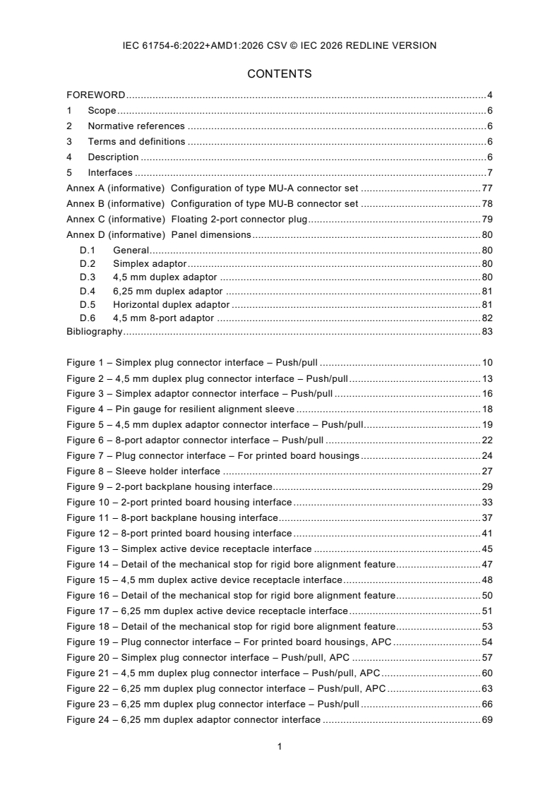
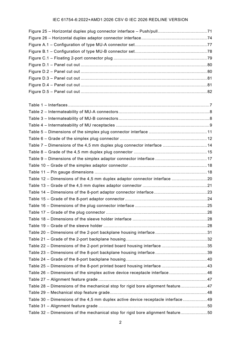
IEC 61754-6:2022+AMD1:2026 CSV - Fibre optic interconnecting devices and passive components - Fibre optic connector interfaces - Part 6: Type MU connector family
IEC 61754-6:2022 - Fibre optic interconnecting devices and passive components - Fibre optic connector interfaces - Part 6: Type MU connector family Released:2/28/2022
Overview
IEC 61754-6:2022 - "Fibre optic interconnecting devices and passive components - Fibre optic connector interfaces - Part 6: Type MU connector family" - specifies the standard interface dimensions and mechanical requirements for the Type MU connector family. This third edition (2022) cancels and replaces the 2013 edition and adds technical updates including the ferrule compression test method (IEC 61300-3-22) and an informative Annex D with panel cut‑out dimensions for strength testing of mounted adaptors. The publication contains detailed figures, dimensional tables and intermateability tables for MU plug, adaptor and receptacle configurations.
Key topics and requirements
- Interface dimensions for Type MU connectors: simplex, duplex (4.5 mm, 6.25 mm), horizontal duplex, 8‑port adaptors, and PCB/backplane housings - complete with dimensional tables and grades.
- Intermateability matrixes defining compatible MU-A and MU-B connector sets and receptacles.
- Mechanical features: alignment sleeves, mechanical stops, sleeve holders and rigid bore alignment features; grades and tolerances are specified in the tables and figures.
- Added test method: incorporation of IEC 61300-3-22 for measuring compression force of the ferrule, enhancing mechanical reliability verification.
- Panel cut‑out guidance: Annex D (informative) provides cut‑out and panel dimension requirements for testing the strength of mounted adaptors.
- Illustrations and tables: extensive figures (plug/adaptor/receptacle layouts) and dimensional tables for design and verification.
Practical applications and who uses this standard
IEC 61754-6 is essential for organizations involved in the design, manufacture, installation and testing of optical fibre equipment that uses Type MU connectors:
- Connector and adaptor manufacturers - to design parts that meet international mechanical interface and intermateability requirements.
- Module, transceiver and active device designers - to specify receptacle footprints for PCBs, backplanes and chassis.
- Test laboratories and QA teams - to verify mechanical conformity and use the referenced ferrule compression test.
- Systems integrators and installers in telecommunications, data centres, FTTx, and enterprise networks - to ensure component compatibility and reliable mechanical performance.
- Standards and compliance engineers - for product certification and interoperability validation.
Related standards
- IEC 61300 series (fibre optic test procedures), notably IEC 61300-3-22 for ferrule compression force.
- Other parts of the IEC 61754 series covering different connector families and interface specifications.
Keywords: IEC 61754-6, Type MU connector, fibre optic connector interfaces, interface dimensions, ferrule compression test, mounted adaptor panel dimensions, optical fibre connectors, intermateability.
Relations
- Effective Date
- 20-Dec-2024
- Effective Date
- 05-Sep-2023
Buy Documents
IEC 61754-6:2022 RLV - Fibre optic interconnecting devices and passive components - Fibre optic connector interfaces - Part 6: Type MU connector family Released:2/28/2022
IEC 61754-6:2022+AMD1:2026 CSV - Fibre optic interconnecting devices and passive components - Fibre optic connector interfaces - Part 6: Type MU connector family
IEC 61754-6:2022 - Fibre optic interconnecting devices and passive components - Fibre optic connector interfaces - Part 6: Type MU connector family Released:2/28/2022
Get Certified
Connect with accredited certification bodies for this standard

ANCE
Mexican certification and testing association.

Intertek Slovenia
Intertek testing, inspection, and certification services in Slovenia.

LNE (Laboratoire National de Métrologie et d'Essais)
French national laboratory for metrology and testing.
Sponsored listings
Frequently Asked Questions
IEC 61754-6:2022 is a standard published by the International Electrotechnical Commission (IEC). Its full title is "Fibre optic interconnecting devices and passive components - Fibre optic connector interfaces - Part 6: Type MU connector family". This standard covers: IEC 61754-6:2022 specifies the standard interface dimensions for type MU family of connectors. This third edition cancels and replaces the second edition published in 2013 and constitutes a technical revision. This edition includes the following significant technical changes with respect to the previous edition: - the test method IEC 61300-3-22 for the compression force of the ferrule was added; - Annex D (informative) with cut out dimension requirements for testing the strength of mounted adaptors was added.
IEC 61754-6:2022 specifies the standard interface dimensions for type MU family of connectors. This third edition cancels and replaces the second edition published in 2013 and constitutes a technical revision. This edition includes the following significant technical changes with respect to the previous edition: - the test method IEC 61300-3-22 for the compression force of the ferrule was added; - Annex D (informative) with cut out dimension requirements for testing the strength of mounted adaptors was added.
IEC 61754-6:2022 is classified under the following ICS (International Classification for Standards) categories: 33.180.20 - Fibre optic interconnecting devices. The ICS classification helps identify the subject area and facilitates finding related standards.
IEC 61754-6:2022 has the following relationships with other standards: It is inter standard links to IEC 61754-6:2022/AMD1:2026, IEC 61754-6:2013. Understanding these relationships helps ensure you are using the most current and applicable version of the standard.
IEC 61754-6:2022 is available in PDF format for immediate download after purchase. The document can be added to your cart and obtained through the secure checkout process. Digital delivery ensures instant access to the complete standard document.
Standards Content (Sample)
IEC 61754-6 ®
Edition 3.0 2022-02
REDLINE VERSION
INTERNATIONAL
STANDARD
colour
inside
Fibre optic interconnecting devices and passive components – Fibre optic
connector interfaces –
Part 6: Type MU connector family
All rights reserved. Unless otherwise specified, no part of this publication may be reproduced or utilized in any form
or by any means, electronic or mechanical, including photocopying and microfilm, without permission in writing from
either IEC or IEC's member National Committee in the country of the requester. If you have any questions about IEC
copyright or have an enquiry about obtaining additional rights to this publication, please contact the address below or
your local IEC member National Committee for further information.
IEC Secretariat Tel.: +41 22 919 02 11
3, rue de Varembé info@iec.ch
CH-1211 Geneva 20 www.iec.ch
Switzerland
About the IEC
The International Electrotechnical Commission (IEC) is the leading global organization that prepares and publishes
International Standards for all electrical, electronic and related technologies.
About IEC publications
The technical content of IEC publications is kept under constant review by the IEC. Please make sure that you have the
latest edition, a corrigendum or an amendment might have been published.
IEC publications search - webstore.iec.ch/advsearchform IEC Products & Services Portal - products.iec.ch
The advanced search enables to find IEC publications by a Discover our powerful search engine and read freely all the
variety of criteria (reference number, text, technical publications previews. With a subscription you will always
committee, …). It also gives information on projects, replaced have access to up to date content tailored to your needs.
and withdrawn publications.
Electropedia - www.electropedia.org
IEC Just Published - webstore.iec.ch/justpublished
The world's leading online dictionary on electrotechnology,
Stay up to date on all new IEC publications. Just Published
containing more than 22 300 terminological entries in English
details all new publications released. Available online and
and French, with equivalent terms in 19 additional languages.
once a month by email.
Also known as the International Electrotechnical Vocabulary
(IEV) online.
IEC Customer Service Centre - webstore.iec.ch/csc
If you wish to give us your feedback on this publication or
need further assistance, please contact the Customer Service
Centre: sales@iec.ch.
IEC 61754-6 ®
Edition 3.0 2022-02
REDLINE VERSION
INTERNATIONAL
STANDARD
colour
inside
Fibre optic interconnecting devices and passive components – Fibre optic
connector interfaces –
Part 6: Type MU connector family
INTERNATIONAL
ELECTROTECHNICAL
COMMISSION
ICS 33.180.20 ISBN 978-2-8322-5124-9
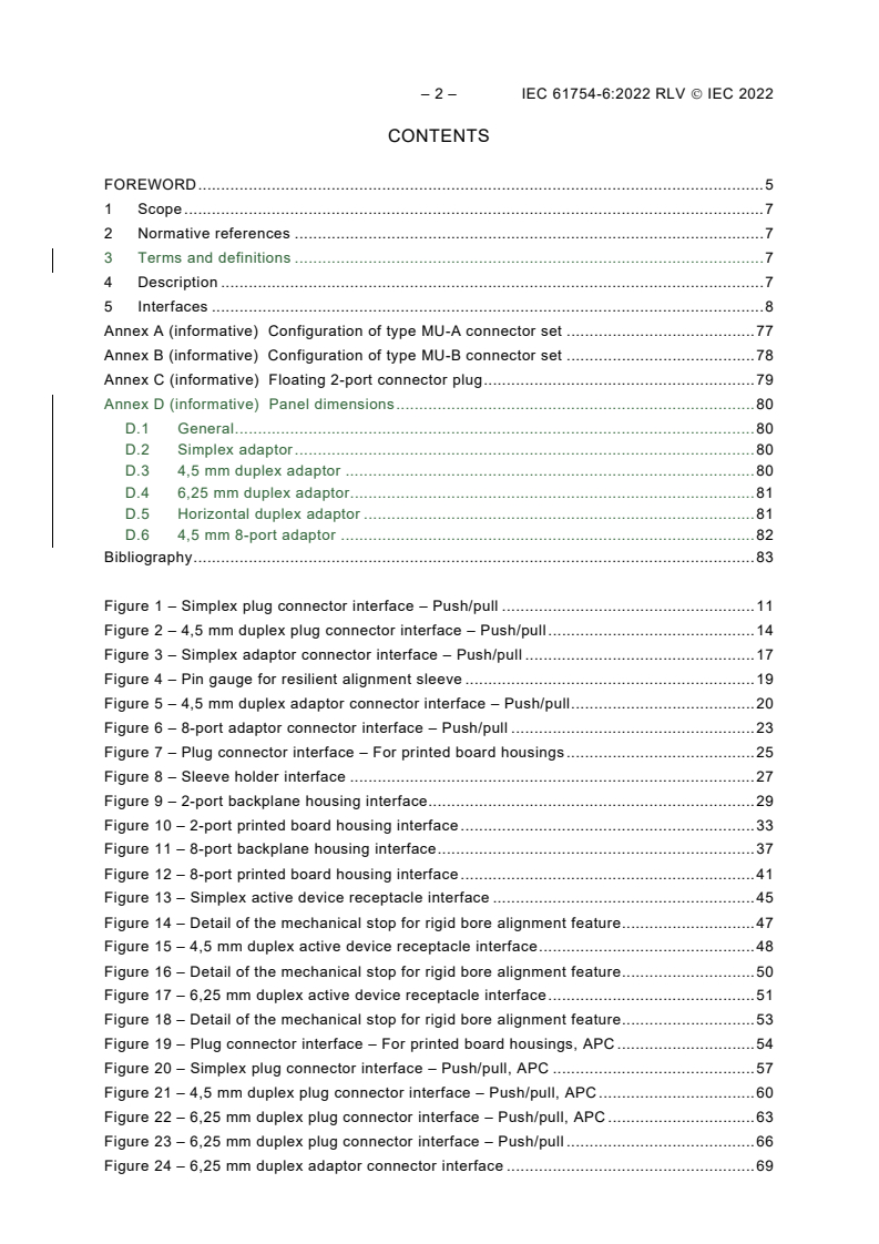
– 2 – IEC 61754-6:2022 RLV IEC 2022
CONTENTS
FOREWORD . 5
1 Scope . 7
2 Normative references . 7
3 Terms and definitions . 7
4 Description . 7
5 Interfaces . 8
Annex A (informative) Configuration of type MU-A connector set . 77
Annex B (informative) Configuration of type MU-B connector set . 78
Annex C (informative) Floating 2-port connector plug . 79
Annex D (informative) Panel dimensions . 80
D.1 General . 80
D.2 Simplex adaptor . 80
D.3 4,5 mm duplex adaptor . 80
D.4 6,25 mm duplex adaptor. 81
D.5 Horizontal duplex adaptor . 81
D.6 4,5 mm 8-port adaptor . 82
Bibliography . 83
Figure 1 – Simplex plug connector interface – Push/pull . 11
Figure 2 – 4,5 mm duplex plug connector interface – Push/pull . 14
Figure 3 – Simplex adaptor connector interface – Push/pull . 17
Figure 4 – Pin gauge for resilient alignment sleeve . 19
Figure 5 – 4,5 mm duplex adaptor connector interface – Push/pull . 20
Figure 6 – 8-port adaptor connector interface – Push/pull . 23
Figure 7 – Plug connector interface – For printed board housings . 25
Figure 8 – Sleeve holder interface . 27
Figure 9 – 2-port backplane housing interface . 29
Figure 10 – 2-port printed board housing interface . 33
Figure 11 – 8-port backplane housing interface . 37
Figure 12 – 8-port printed board housing interface . 41
Figure 13 – Simplex active device receptacle interface . 45
Figure 14 – Detail of the mechanical stop for rigid bore alignment feature . 47
Figure 15 – 4,5 mm duplex active device receptacle interface . 48
Figure 16 – Detail of the mechanical stop for rigid bore alignment feature . 50
Figure 17 – 6,25 mm duplex active device receptacle interface . 51
Figure 18 – Detail of the mechanical stop for rigid bore alignment feature . 53
Figure 19 – Plug connector interface – For printed board housings, APC . 54
Figure 20 – Simplex plug connector interface – Push/pull, APC . 57
Figure 21 – 4,5 mm duplex plug connector interface – Push/pull, APC . 60
Figure 22 – 6,25 mm duplex plug connector interface – Push/pull, APC . 63
Figure 23 – 6,25 mm duplex plug connector interface – Push/pull . 66
Figure 24 – 6,25 mm duplex adaptor connector interface . 69
Figure 25 – Horizontal duplex plug connector interface – Push/pull . 71
Figure 26 – Horizontal duplex adaptor connector interface . 74
Figure A.1 – Configuration of type MU-A connector set . 77
Figure B.1 – Configuration of type MU-B connector set . 78
Figure C.1 – Floating 2-port connector plug . 79
Figure D.1 – Panel cut out . 80
Figure D.2 – Panel cut out . 80
Figure D.3 – Panel cut out . 81
Figure D.4 – Panel cut out . 81
Figure D.5 – Panel cut out . 82
Table 1 – Interfaces . 8
Table 2 – Intermateability of MU-A connectors set . 9
Table 3 – Intermateability of MU-B connectors set . 9
Table 4 – Intermateability of MU receptacles . 10
Table 5 – Dimensions of the simplex plug connector interface . 12
Table 6 – Grade of the simplex plug connector . 13
Table 7 – Dimensions of the 4,5 mm duplex plug connector interface . 14
Table 8 – Grade of the 4,5 mm duplex plug connector . 16
Table 9 – Dimensions of the simplex adaptor connector interface . 18
Table 10 – Grade of the simplex adaptor connector . 19
Table 11 – Pin gauge dimensions . 19
Table 12 – Dimensions of the 4,5 mm duplex adaptor connector interface . 21
Table 13 – Grade of the 4,5 mm duplex adaptor connector . 22
Table 14 – Dimensions of the 8-port adaptor connector interface . 24
Table 15 – Grade of the 8-port adaptor connector . 25
Table 16 – Dimensions of the plug connector interface . 26
Table 17 – Grade of the plug connector . 27
Table 18 – Dimensions of the sleeve holder interface . 28
Table 19 – Grade of the sleeve holder . 28
Table 20 – Dimensions of the 2-port backplane housing interface . 31
Table 21 – Grade of the 2-port backplane housing . 32
Table 22 – Dimensions of the 2-port printed board housing interface . 35
Table 23 – Dimensions of the 8-port backplane housing interface . 39
Table 24 – Grade of the 8-port backplane housing . 40
Table 25 – Dimensions of the 8-port printed board housing interface . 43
Table 26 – Dimensions of the simplex active device receptacle interface . 46
Table 27 – Alignment feature grade . 47
Table 28 – Dimensions of the mechanical stop for rigid bore alignment feature . 47
Table 29 – Mechanical stop feature grade . 48
Table 30 – Dimensions of the 4,5 mm duplex active device receptacle interface . 49
Table 31 – Alignment feature grade . 50
Table 32 – Dimensions of the mechanical stop for rigid bore alignment feature . 50
– 4 – IEC 61754-6:2022 RLV IEC 2022
Table 33 – Mechanical stop feature grade . 51
Table 34 – Dimensions of the 6,25 mm duplex active device receptacle interface . 52
Table 35 – Alignment feature grade . 53
Table 36 – Dimensions of the mechanical stop for rigid bore alignment feature . 53
Table 37 – Mechanical stop feature grade . 54
Table 38 – Dimensions of the plug connector interface – For printed board housings, APC . 56
Table 39 – Dimensions of the simplex plug connector interfaces, APC . 58
Table 40 – Dimensions of the 4,5 mm duplex plug connector interfaces, APC . 61
Table 41 – Dimensions of the 6,25 mm duplex plug connector interface, APC . 64
Table 42 – Dimensions of the 6,25 mm duplex plug connector interface . 66
Table 43 – Grade . 68
Table 44 – Dimensions of the 6,25 mm duplex adaptor connector interface . 69
Table 45 – Grade of the 6,25 mm duplex adaptor connector . 70
Table 46 – Dimensions of the horizontal duplex plug connector interface . 72
Table 47 – Grade of the horizontal duplex plug connector . 73
Table 48 – Dimensions of the horizontal duplex adaptor connector interface . 75
Table 49 – Grade of the horizontal duplex adaptor connector . 76
Table C.1 – Dimensions table for 2-port connector plug . 79
Table D.1 – Dimensions for simplex adaptor . 80
Table D.2 – Dimensions for 4,5 mm duplex adaptor . 81
Table D.3 – Dimensions for 6,25 mm duplex adaptor . 81
Table D.4 – Dimensions for horizontal duplex adaptor . 82
Table D.5 – Dimensions for 4,5 mm 8-port adaptor . 82
INTERNATIONAL ELECTROTECHNICAL COMMISSION
____________
FIBRE OPTIC INTERCONNECTING
DEVICES AND PASSIVE COMPONENTS –
FIBRE OPTIC CONNECTOR INTERFACES –
Part 6: Type MU connector family
FOREWORD
1) The International Electrotechnical Commission (IEC) is a worldwide organization for standardization comprising
all national electrotechnical committees (IEC National Committees). The object of IEC is to promote international
co-operation on all questions concerning standardization in the electrical and electronic fields. To this end and
in addition to other activities, IEC publishes International Standards, Technical Specifications, Technical Reports,
Publicly Available Specifications (PAS) and Guides (hereafter referred to as “IEC Publication(s)”). Their
preparation is entrusted to technical committees; any IEC National Committee interested in the subject dealt with
may participate in this preparatory work. International, governmental and non-governmental organizations liaising
with the IEC also participate in this preparation. IEC collaborates closely with the International Organization for
Standardization (ISO) in accordance with conditions determined by agreement between the two organizations.
2) The formal decisions or agreements of IEC on technical matters express, as nearly as possible, an international
consensus of opinion on the relevant subjects since each technical committee has representation from all
interested IEC National Committees.
3) IEC Publications have the form of recommendations for international use and are accepted by IEC National
Committees in that sense. While all reasonable efforts are made to ensure that the technical content of IEC
Publications is accurate, IEC cannot be held responsible for the way in which they are used or for any
misinterpretation by any end user.
4) In order to promote international uniformity, IEC National Committees undertake to apply IEC Publications
transparently to the maximum extent possible in their national and regional publications. Any divergence between
any IEC Publication and the corresponding national or regional publication shall be clearly indicated in the latter.
5) IEC itself does not provide any attestation of conformity. Independent certification bodies provide conformity
assessment services and, in some areas, access to IEC marks of conformity. IEC is not responsible for any
services carried out by independent certification bodies.
6) All users should ensure that they have the latest edition of this publication.
7) No liability shall attach to IEC or its directors, employees, servants or agents including individual experts and
members of its technical committees and IEC National Committees for any personal injury, property damage or
other damage of any nature whatsoever, whether direct or indirect, or for costs (including legal fees) and
expenses arising out of the publication, use of, or reliance upon, this IEC Publication or any other IEC
Publications.
8) Attention is drawn to the Normative references cited in this publication. Use of the referenced publications is
indispensable for the correct application of this publication.
9) Attention is drawn to the possibility that some of the elements of this IEC Publication may be the subject of patent
rights. IEC shall not be held responsible for identifying any or all such patent rights.
This redline version of the official IEC Standard allows the user to identify the changes made to
the previous edition IEC 61754-6:2013. A vertical bar appears in the margin wherever a change
has been made. Additions are in green text, deletions are in strikethrough red text.
– 6 – IEC 61754-6:2022 RLV IEC 2022
IEC 61754-6 has been prepared by subcommittee 86B: Fibre optic interconnecting devices and
passive components, of IEC technical committee 86: Fibre optics. It is an International Standard.
This third edition cancels and replaces the second edition published in 2013 and constitutes a
technical revision.
This edition includes the following significant technical changes with respect to the previous
edition:
a) the test method IEC 61300-3-22 for the compression force of the ferrule was added;
b) Annex D (informative) with cut out dimension requirements for testing the strength of
mounted adaptors was added.
The text of this International Standard is based on the following documents:
Draft Report on voting
86B/4562/FDIS 86B/4585/RVD
Full information on the voting for its approval can be found in the report on voting indicated in
the above table.
The language used for the development of this International Standard is English.
This document was drafted in accordance with ISO/IEC Directives, Part 2, and developed in
accordance with ISO/IEC Directives, Part 1 and ISO/IEC Directives, IEC Supplement, available
at www.iec.ch/members_experts/refdocs. The main document types developed by IEC are
described in greater detail at www.iec.ch/standardsdev/publications.
A list of all parts of the IEC 61754 series, under the general title Fibre optic interconnecting
devices and passive components – Fibre optic connector interfaces, can be found on the IEC
website.
Future standards in this series will carry the new general title as cited above. Titles of existing
standards in this series will be updated at the time of the next edition.
The committee has decided that the contents of this document will remain unchanged until the
stability date indicated on the IEC website under webstore.iec.ch in the data related to the
specific document. At this date, the document will be
• reconfirmed,
• withdrawn,
• replaced by a revised edition, or
• amended.
IMPORTANT – The 'colour inside' logo on the cover page of this publication indicates that it
contains colours which are considered to be useful for the correct understanding of its
contents. Users should therefore print this document using a colour printer.
FIBRE OPTIC INTERCONNECTING
DEVICES AND PASSIVE COMPONENTS –
FIBRE OPTIC CONNECTOR INTERFACES –
Part 6: Type MU connector family
1 Scope
This part of IEC 61754 defines specifies the standard interface dimensions for type MU family
of connectors.
2 Normative references
The following documents are referred to in the text in such a way that some or all of their content
constitutes requirements of this document. For dated references, only the edition cited applies.
For undated references, the latest edition of the referenced document (including any
amendments) applies.
IEC 61755-3-1, Fibre optic connector optical interfaces – Part 3-1:Optical interface, 2,5 mm and
1,25 mm diameter cylindrical full zirconia PC ferrule, single mode fibre
IEC 61755-3-2, Fibre optic connector optical interfaces – Part 3-2: Optical interface, 2,5 mm
and 1,25 mm diameter cylindrical full zirconia ferrules for 8 degrees angled-PC single mode
fibres
IEC 61300-3-22, Fibre optic interconnecting devices and passive components – Basic test and
measurement procedures – Part 3-22: Examinations and measurements – Ferrule compression
force
IEC 61754-1, Fibre optic interconnecting devices and passive components – Fibre optic
connector interfaces – Part 1: General and guidance
3 Terms and definitions
For the purposes of this document, the terms and definitions given in IEC 61754-1 apply.
ISO and IEC maintain terminological databases for use in standardization at the following
addresses:
• IEC Electropedia: available at http://www.electropedia.org/
• ISO Online browsing platform: available at http://www.iso.org/obp
4 Description
The parent connector for type MU connector family is a miniature single-position plug which is
characterized by a cylindrical, spring-loaded butting ferrule(s) of a 1,25 mm typical diameter,
and a push-pull coupling mechanism. The optical alignment mechanism of the connectors is of
a rigid hole or a resilient sleeve style.
This document type MU connector family defines the standard interface dimensions of active
device receptacles for the type MU connectors. The receptacles are used to retain the connector
– 8 – IEC 61754-6:2022 RLV IEC 2022
plugs and mechanically maintain the optical datum target of the plugs at a defined position
within the receptacle housings.
5 Interfaces
This document contains the standard interfaces showed in Table 1.
Table 1 – Interfaces
Interface IEC 61754-6-1 Simplex plug connector interface – Push/pull (see Figure 1)
Interface IEC 61754-6-2 4,5 mm duplex plug connector interface – Push/pull (see Figure 2)
Interface IEC 61754-6-3 Simplex adaptor connector interface – Push/pull (see Figure 3)
Interface IEC 61754-6-4 4,5 mm duplex adaptor connector interface – Push/pull (see Figure 5)
Interface IEC 61754-6-5 8-port adaptor connector interface – Push/pull (see Figure 6)
Interface IEC 61754-6-6 Plug connector interface – for printed board housings (see Figure 7)
Interface IEC 61754-6-7 Sleeve holder interface – for printed board housings (see Figure 8)
Interface IEC 61754-6-8 2-port backplane housing interface – Self-retentive (see Figure 9)
Interface IEC 61754-6-9 2-port printed board housing interface – Self-retentive (see Figure 10)
Interface IEC 61754-6-10 8-port backplane housing interface – Self-retentive (see Figure 11)
Interface IEC 61754-6-11 8-port printed board housing interface – Self-retentive (see Figure 12)
Interface IEC 61754-6-12 Simplex active device receptacle interface – for physical contact (PC) connector
plug (see Figure 13)
Interface IEC 61754-6-13 4,5 mm duplex active device receptacle interface – for PC connector plug
(see Figure 15)
Interface IEC 61754-6-14 6,25 mm duplex active device receptacle interface – for PC connector plug
(see Figure 17)
Interface IEC 61754-6-15 Plug connector interface – for printed board housings, angled PC (APC) 8
degrees (see Figure 19)
Interface IEC 61754-6-16 Simplex plug connector interface – Push/pull, APC 8 degrees (see Figure 20)
Interface IEC 61754-6-17 4,5 mm duplex plug connector interface – Push/pull, APC 8 degrees
(see Figure 21)
Interface IEC 61754-6-18 6,25 mm duplex plug connector interface – Push/pull, APC 8 degrees
(see Figure 22)
Interface IEC 61754-6-19 6,25 mm duplex plug connector interface – Push/pull (see Figure 23)
Interface IEC 61754-6-20 6,25 mm duplex adaptor connector interface – Push/pull (see Figure 24)
Interface IEC 61754-6-21 Horizontal duplex plug connector interface – Push/pull (see Figure 25)
Interface IEC 61754-6-22 Horizontal duplex adaptor connector interface – Push/pull (see Figure 26)
The plugs of interfaces IEC 61754-6-1, IEC 61754-6-2, IEC 61754-6-6, IEC 61754-6-19 and
IEC 61754-6-21 have a ferrule(s) with a spherically polished endface, and realize physical
contact (PC). The plugs of interfaces IEC 61754-6-15, IEC 61754-6-16, IEC 61754-6-17 and
IEC 61754-6-18 have a ferrule(s) with a spherically polished angled endface and realize angled
PC (APC).
The type MU connector family comprises two types of connector set: MU-A connector set
(see Annex A) and MU-B connector set (see Annex B). The MU-A connector set is a
plug/adaptor configuration with a push-pull coupling mechanism. The MU-B connector set is a
plug-in type back-plane connector configuration which is plug/backplane and printed board
housings/plug for printed board housing/sleeve holder configuration and is equipped with a self-
retentive mechanism.
The type MU-A connector set consists of simplex and duplex plugs, and simplex, duplex and
8-port adaptors. The plugs are common to the backplane connector housings of the type MU-B
connector set.
The type MU-B connector set consists of 2-port and 8-port backplane and printed board
connector housings, simplex and duplex plugs, plug for printed board connector housings, and
sleeve holder. The plug for printed board connector housing is used as a jack together with the
sleeve holder. The jack is attached into the printed board connector housing.
Table 2, Table 3 and Table 4 show the intermateablitiy of the standard interfaces. It shall be
noted however that in order to obtain the designated optical performance, any plug shall be
connected to a counterpart plug whose ferrule end is polished to the same condition.
Table 2 – Intermateability of MU-A connectors set
Adaptors
Plugs
61754-6-3 61754-6-4 61754-6-5 61754-6-20 61754- 6-22
61754-6-1 Mate Mate Mate Mate Mate
61754-6-2 Not mate Mate Mate Not mate Not mate
61754-6-16 Mate Mate Mate Mate Mate
61754- 6-17 Not mate Mate Mate Not mate Not mate
61754-6-18 Not mate Not mate Not mate Mate Not mate
61754-6-19 Not mate Not mate Not mate Mate Not mate
61754-6-21 Not mate Not mate Not mate Not mate Mate
Table 3 – Intermateability of MU-B connectors set
Connector housings
Backplane connector Printed board connector
Plugs
housing housing
61754-6-8 61754-6-10 61754-6-9 61754-6-11
61754-6-1 Mate Mate Not mate Not mate
61754-6-2 Mate Mate Not mate Not mate
61754-6-6 with 61754-6-7 Not mate Not mate Mate Mate
61754-6-15 with 61754- 6-7
Not mate Not mate Mate Mate
61754-6-16 Mate Mate Not mate Not mate
61754-6-17 Mate Mate Not mate Not mate
61754-6-18 Not mate Not mate Not mate Not mate
61754-6-19 Not mate Not mate Not mate Not mate
61754-6-21 Not mate Not mate Not mate Not mate
– 10 – IEC 61754-6:2022 RLV IEC 2022
Table 4 – Intermateability of MU receptacles
Receptacles
Plugs
61754-6-12 61754-6-13 61754-6-14
61754-6-1 Mate Mate Mate
61754-6-2 Not mate Mate Not mate
61754-6-16 Not mate Not mate Not mate
61754-6-17 Not mate Not mate Not mate
61754-6-18 Not mate Not mate Not mate
61754-6-19 Not mate Not mate Mate
61754-6-21 Not mate Not mate Not mate
Figure 1 is an example of a simplex plug connector interface. Table 5 gives dimensions of the
simplex plug connector interface and Table 6 gives the grade of the simplex plug connector
interface.
Figure 1 – Simplex plug connector interface – Push/pull
– 12 – IEC 61754-6:2022 RLV IEC 2022
Table 5 – Dimensions of the simplex plug connector interface
Dimensions
Reference Remarks
Minimum Maximum
a
A 1,249 5 mm
See Table 6
B 2,6 mm 2,7 mm
C 4,6 mm 4,8 mm
D 4,65 mm 4,75 mm
E 4,3 mm 4,4 mm
F 3,3 mm 3,4 mm
G
25° 35° Angle, unit in degrees
H 25° 35° Angle, unit in degrees
b
I 6,55 mm –
c
J 4,2 mm 4,5 mm
K
5,5 mm –
L 2,4 mm 2,5 mm
M 1,5 mm –
N 0,6 mm –
O 0,5 mm –
b
P 2,6 mm –
b d
Q 1 mm 1,1 mm
b
R 2,65 mm 2,9 mm
S 5,5 mm 5,6 mm
T 4,3 mm 4,5 mm
U
– 3,7 mm
V – 2,4 mm
W 6,5 mm 6,6 mm
AA
4,3 mm 4,4 mm
AB 3,85 mm 3,95 mm
AC 0,7 mm 0,9 mm
AD 0,2 mm – Radius
AE 3 mm –
AF 2,2 mm 2,3 mm
e
EA 32,5° 45°
Angle, unit in degrees
f
EB 5 mm 30 mm
Radius
EC 0,45 mm 0,73 mm Diameter
a
A chamfer or radius is allowed to a maximum depth of 0,5 mm from the ferrule endface.
b
The delatch housing shall be movable to the right and or left directions. Dimensions L, M and V
are given when the coupling sleeve is moved in its most right-direction position delatch housing
is at the furthest right.
c
Dimension J is given for the plug endface when not mated. It is noticed that The ferrule is movable
by a certain axial compression force with direct contacting endfaces, and therefore dimension J
is variable. Ferrule compression force shall be 5,5 N to 6,5 N when the position of the optical
datum target from the mechanical datum target is moved in the range of 3,9 mm to 4,1 mm. In
addition, dimension J shall become less than 3,25 mm with a relatively large axial compression
force. The compression force shall be measured according to IEC 61300-3-22.
d
The right-side position of Q shall become the left-side position to the mechanical datum target
when the coupling sleeve is moved to its most left-direction position. Q is to the right of the
mechanical datum target when the delatch housing is to the right (connected state) and to the
left of the mechanical datum target when the delatch housing is to the left (disconnected state).
e
40° to 45° are desirable to minimize debris for backplane connectors.
f
Dome eccentricity of the spherically polished ferrule endface shall be less than 70 50 µm.
Table 6 – Grade of the simplex plug connector
Dimensions
mm
Grade Remarks
A
Minimum Maximum
a
A See IEC 61755-3-1
a
B See IEC 61755-3-1
a
C See IEC 61755-3-1
a
D See IEC 61755-3-1
b
Am 1,248 3 1,249 5
b
Bm 1.246 7 1,249 5
a b
A Grade not specified at this time
m
a b
B 1,246 7 1,249 5
m
a b
C Grade not specified at this time
m
a
See IEC 61755-3-1. Add grade number to the interface reference number.
b 1
See IEC 61755-6-1 for guidance.
Figure 2 is an example of a 4,5 mm duplex plug connector interface. Table 7 gives dimensions
of the 4,5 mm duplex plug connector interface and Table 8 gives the grade of the 4,5 mm duplex
plug connector interface.
___________
Under preparation. Stage at the time of publication: IEC/CDM 61755-6-1:2021.
– 14 – IEC 61754-6:2022 RLV IEC 2022
Figure 2 – 4,5 mm duplex plug connector interface – Push/pull
Table 7 – Dimensions of the 4,5 mm duplex plug connector interface
Dimensions
Reference Remarks
Minimum Maximum
a
A 1,249 5 mm
See Table 8
B 2,6 mm 2,7 mm
C 4,6 mm 4,8 mm
D
4,65 mm 4,75 mm
E 4,3 mm 4,4 mm
F 3,3 mm 3,4 mm
G 25° 35° Angle, unit in degrees
H 25° 35° Angle, unit in degrees
b
I 6,55 mm –
c
J 4,2 mm 4,5 mm
K 5,5 mm –
L 2,4 mm 2,5 mm
M 1,5 mm –
N
0,6 mm –
O 0,5 mm –
b
P 2,6 mm –
b d
Q
1,0 mm 1,1 mm
b
R 2,65 mm 2,9 mm
S 5,5 mm 5,6 mm
T 4,3 mm 4,5 mm
U – 3,7 mm
V – 2,4 mm
W 6,5 mm 6,6 mm
AB
3,7 mm 3,85 mm
AC 0,7 mm 0,9 mm
AD 0,2 mm – Radius
AE 3,0 mm –
AF 2,2 mm 2,3 mm
AJ 8,8 mm 8,9 mm
AK 8,35 mm 8,45 mm
AL 4,55 mm 4,7 mm
AM 4,45 mm 4,55 mm
AP – 3,7 mm
e
EA
32,5° 45°
Angle, unit in degrees
f
EB 5 mm 30 mm
Radius
EC 0,45 mm 0,73 mm Diameter
a
A chamfer or radius is allowed to a maximum depth of 0,5 mm from the ferrule endface.
b
The delatch housing shall be movable to the right and or left directions. Dimensions L, M and V
are given when the coupling sleeve is moved in its most right-direction position delatch housing
is at the furthest right.
c
Dimension J is given for the plug endface when not mated. It is noticed that The ferrule is movable
by a certain axial compression force with direct contacting endfaces, and therefore dimension J
is variable. Ferrule compression force shall be 5,5 N to 6,5 N when the position of the optical
datum target from the mechanical datum target is moved in the range of 3,9 mm to 4,1 mm. In
addition, dimension J shall become less than 3,25 mm with a relatively large axial compression
force. The compression force shall be measured according to IEC 61300-3-22.
d
The right-side position of Q shall become left-side position to the mechanical datum target when
the coupling sleeve is moved to its most left-direction position. Q is to the right of the mechanical
datum target when the delatch housing is to the right (connected state) and to the left of the
mechanical datum target when the delatch housing is to the left (disconnected state).
e
40° to 45° are desirable to minimize debris for backplane connectors.
f
Dome eccentricity of the spherically polished ferrule endface shall be less than 70 50 μm.
– 16 – IEC 61754-6:2022 RLV IEC 2022
Table 8 – Grade of the 4,5 mm duplex plug connector
Dimensions
Grade A Remarks
Minimum Maximum
a
A See IEC 61755-3-1
a
B See IEC 61755-3-1
a
C See IEC 61755-3-1
a
D See IEC 61755-3-1
b
Am 1,248 3 1,249 5
b
Bm 1,246 7 1,249 5
a b
A Grade not specified at this time
m
a b
B 1,246 7 1,249 5
m
a b
C Grade not specified at this time
m
a
See IEC 61755-3-1. Add grade number to the interface reference number.
b
See IEC 61755-6-1 for guidance.
Figure 3 is an example of a simplex adaptor connector interface. Table 9 gives dimensions of
the simplex adaptor connector interface and Table 10 gives the grade of the simplex adaptor
connector interface.
Figure 3 – Simplex adaptor connector interface – Push/pull
– 18 – IEC 61754-6:2022 RLV IEC 2022
Table 9 – Dimensions of the simplex adaptor connector interface
Dimensions
mm
Reference Remarks
Minimum Maximum
A See Table 10 Diameter
B 2,39 2,59 Diameter
D 4,8 5
E 4,55 –
a
F 2,9 3,5
I – 6,5
J 3,9 4,1
K – 5,4
L 2,55 2,7
M – 1,4
N – 0,55
O – 0,6
P – 1,2
Q – 0,4
R – 2,55
S 5,65 5,75
U 3,8 4
V 3,3 –
W 6,7 –
AA 4,45 4,55
AB 4,01 4,11
AC 0,95 1,15
AD – 0,2 Radius
AE 2,8 2,95
AF 1,9 2,1
AG 0,3 – Radius
AH 0,4 0,55
AI 1,34 1,44 Diameter
AJ – 0,3 Radius
a
Dimension F shall become greater than 4,5 mm when a plug is coupled to or removed from the
adaptor.
Table 10 – Grade of the simplex adaptor connector
Dimensions
Grade mm Remarks
Minimum Maximum
a
1 – –
Resilient sleeve
a
The connector alignment feature is a resilient alignment sleeve. The feature shall accept a pin
gauge to the centre of the adaptor with a force of 1,0 N to 2,5 N under the condition that another
pin gauge is inserted into the feature from the other side. The centre of the adaptor is defined by
the right-side position of dimension J. The pin gauge is shown in Figure 4 and Table 11.
Figure 4 is an example of a pin gauge for resilient alignment sleeve. Table 11 gives pin gauge
dimensions.
Figure 4 – Pin gauge for resilient alignment sleeve
Table 11 – Pin gauge dimensions
Dimensions
Reference mm Remarks
Minimum Maximum
LK 1,248 5 1,249 5 Surface roughness
grade N4
(0,2 μm radius)
LL 2,6 2,8
LN 4,7 9,5 –
Figure 5 is an example of a 4,5 mm duplex adaptor connector interface. Table 12 gives
dimensions of the 4,5 mm duplex adaptor connector interface and Table 13 gives the grade of
the 4,5 mm duplex adaptor connector interface.
– 20 – IEC 61754-6:2022 RLV IEC 2022
Figure 5 – 4,5 mm duplex adaptor connector interface – Push/pull
Table 12 – Dimensions of the 4,5 mm duplex adaptor connector interface
Dimensions
mm
Reference Remarks
Minimum Maximum
A See Table 13
B 2,39 2,59
D 4,8 5
E 4,55 –
a
F 2,9 3,5
I – 6,5
J 3,9 4,1
K – 5,4
L 2,55 2,7
M – 1,4
N – 0,55
O – 0,6
P – 1,2
Q – 0,4
R – 2,55
S 5,65 5,75
U 3,8 4
V 3,3 –
W 6,7 –
AA 4,45 4,55
AB 4,01 4,11
AC 0,95 1,15
AD – 0,2 Radius
AE 2,8 2,95
AF 1,9 2,1
AG 0,3 – Radius
AH 0,4 0,55
AI 1,34 1,44 Diameter
AJ – 0,3 Radius
AM 4,45 4,55
AP 3,8 4
a
Dimension F shall become greater than 4,5 mm when a plug is coupled to or removed from the
adaptor.
– 22 – IEC 61754-6:2022 RLV IEC 2022
Table 13 – Grade of the 4,5 mm duplex adaptor connector
Dimensions
Grade mm Notes
Minimum Maximum
a
1 – –
Resilient sleeve
a
The connector alignment feature is a resilient alignment sleeve. The feature shall accept a pin
gauge to the centre of the adaptor with a force of 1,0 N to 2,5 N under the condition that another
pin gauge is inserted into the feature from the other side. The centre of the adaptor is defined by
the right-side position of dimension J. The pin gauge is shown in Figure 4 and Table 11.
Figure 6 is an example of an 8-port adaptor connector interface. Table 14 gives dimensions of
the 8-port adaptor connector interface and Table 15 gives the grade of the 8-port adaptor
connector interface.
Figure 6 – 8-port adaptor connector interface – Push/pull
– 24 – IEC 61754-6:2022 RLV IEC 2022
Table 14 – Dimensions of the 8-port adaptor connector interface
Dimensions
mm
Reference Remarks
Minimum Maximum
A See Table 15
B 2,39 2,59
D 4,8 5
E 4,55 –
a
F 2,9 3,5
I – 6,5
J 3,9 4,1
K – 5,4
L 2,55 2,7
M – 1,4
N – 0,55
O – 0,6
P – 1,2
Q – 0,4
R – 2,55
S 5,65 5,75
U 3,8 4
V 3,3 –
W 6,7 –
AA 4,45 4,55
AB 4,01 4,11
AC 0,95 1,15
AD – 0,2 Radius
AE 2,8 2,95
AF 1,9 2,1
AG 0,3 – Radius
AH 0,4 0,55
AI 1,34 1,44 Diameter
AJ – 0,3 Radius
AM 4,45 4,55
AP 3,8 4
AQ 4,8 5,2
a
Dimension F shall become greater than 4,5 mm when a plug is coupled to or removed from the
adaptor.
Table 15 – Grade of the 8-port adaptor connector
Dimensions
Grade mm Notes
Minimum Maximum
a
1 – –
Resilient sleeve
a
The connector alignment feature is a resilient alignment sleeve. The feature shall accept a pin
gauge to the centre of the adaptor with a force of 1,0 N to 2,5 N under the condition that another
pin gauge is inserted into the feature from the other side. The centre of the adaptor is defined by
the right-side position of dimension J. The pin gauge is shown in Figure 4 and Table 11.
Figure 7 is an example of a plug connector interface. Table 16 gives dimensions of the plug
connector interface and Table 17 gives the grade of the plug connector interface.
Figure 7 – Plug connector interface – For printed board housings
– 26 – IEC 61754-6:2022 RLV IEC 2022
Table 16 – Dimensions of the plug connector interface
Dimensions
Reference Notes
Minimum Maximum
a
A 1,249 5 mm
See Table 17
B 2,6 mm 2,7 mm Diameter
D 4,65 mm 4,75 mm
E 4,3 mm 4,4 mm
F 3,3 mm 3,4 mm
b
J 4,2 mm 4,5 mm
K 5,5 mm –
L 2,4 mm 2,5 mm
M 1,5 mm –
N 0,6 mm –
O 0,5 mm –
AR 3,65 mm 3,75 mm
AS 2,9 mm 3,0 mm
AT 1,7 mm 2,1 mm
AU 43° 47° Angle, unit in degrees
AV – 3,0 mm
c
EA 32,5° 45°
Angle, unit in degrees
d
EB 5 mm 30 mm
Radius
EC 0,45 mm 0,73 mm
NOTE 1 A chamfer or radius is allowed to a maximum depth of 0,5 mm from the ferrule endface.
NOTE 2 40° to 45° are desirable to minimize debris for backplane connectors.
a
A chamfer or radius is allowed to a maximum depth of 0,5 mm from the ferrule endface.
b
Dimension J is given for the plug endface when not mated. It is noticed that The ferrule is movable
by a certain axial compression force with direct contacting endfaces, and therefore dimension J
is variable. Ferrule compression force shall be 5,5 N to 6,5 N when the position of the optical
datum target from the mechanical datum target is moved in the range of 3,9 mm to 4,1 mm. In
addition, dimension J shall become less than 3,25 mm with a relatively large axial compression
force. The compression force shall be measured according to IEC 61300-3-22.
c
40° to 45° are desirable to minimize debris for backplane connectors.
d
Dome eccentricity of the spherically polished ferrule endface shall be less than 70 50 μm.
Table 17 – Grade of the plug connector
Dimensions
mm
Grade Notes
A
Minimum Maximum
a
A See IEC 61755-3-1
a
B See IEC 61755-3-1
a
C See IEC 61755-3-1
a
D See IEC 61755-3-1
b
Am 1,248 3 1,249 5
b
Bm 1,246 7 1,249 5
a b
A Grade not specified at this time
m
a b
B 1,246 7 1,249 5
m
a b
C Grade not specified at this time
m
a
See IEC 61755-3-1. Add grade number to the interface reference number.
b
See IEC 61755-6-1 for guidance .
Figure 8 is an example of the sleeve holder interface. Table 18 gives dimensions of the sleeve
holder interface and Table 19 gives
...
IEC 61754-6 ®
Edition 3.1 2026-10
INTERNATIONAL
STANDARD
CONSOLIDATED VERSION
Fibre optic interconnecting devices and passive components - Fibre optic
connector interfaces -
Part 6: Type MU connector family
ICS 33.180.20 ISBN 978-2-8327-1567-3
All rights reserved. Unless otherwise specified, no part of this publication may be reproduced or utilized in any form or
by any means, electronic or mechanical, including photocopying and microfilm, without permission in writing from either
IEC or IEC's member National Committee in the country of the requester. If you have any questions about IEC copyright
or have an enquiry about obtaining additional rights to this publication, please contact the address below or your local
IEC member National Committee for further information.
IEC Secretariat Tel.: +41 22 919 02 11
3, rue de Varembé info@iec.ch
CH-1211 Geneva 20 www.iec.ch
Switzerland
About the IEC
The International Electrotechnical Commission (IEC) is the leading global organization that prepares and publishes
International Standards for all electrical, electronic and related technologies.
About IEC publications
The technical content of IEC publications is kept under constant review by the IEC. Please make sure that you have the
latest edition, a corrigendum or an amendment might have been published.
IEC publications search - IEC Products & Services Portal - products.iec.ch
webstore.iec.ch/advsearchform Discover our powerful search engine and read freely all the
The advanced search enables to find IEC publications by a publications previews, graphical symbols and the glossary.
variety of criteria (reference number, text, technical With a subscription you will always have access to up to date
committee, …). It also gives information on projects, content tailored to your needs.
replaced and withdrawn publications.
Electropedia - www.electropedia.org
The world's leading online dictionary on electrotechnology,
IEC Just Published - webstore.iec.ch/justpublished
Stay up to date on all new IEC publications. Just Published containing more than 22 500 terminological entries in English
details all new publications released. Available online and and French, with equivalent terms in 25 additional languages.
once a month by email. Also known as the International Electrotechnical Vocabulary
(IEV) online.
IEC Customer Service Centre - webstore.iec.ch/csc
If you wish to give us your feedback on this publication or
need further assistance, please contact the Customer
Service Centre: sales@iec.ch.
CONTENTS
FOREWORD . 4
1 Scope . 6
2 Normative references . 6
3 Terms and definitions . 6
4 Description . 6
5 Interfaces . 7
Annex A (informative) Configuration of type MU-A connector set . 77
Annex B (informative) Configuration of type MU-B connector set . 78
Annex C (informative) Floating 2-port connector plug . 79
Annex D (informative) Panel dimensions . 80
D.1 General . 80
D.2 Simplex adaptor . 80
D.3 4,5 mm duplex adaptor . 80
D.4 6,25 mm duplex adaptor . 81
D.5 Horizontal duplex adaptor . 81
D.6 4,5 mm 8-port adaptor . 82
Bibliography . 83
Figure 1 – Simplex plug connector interface – Push/pull . 10
Figure 2 – 4,5 mm duplex plug connector interface – Push/pull . 13
Figure 3 – Simplex adaptor connector interface – Push/pull . 16
Figure 4 – Pin gauge for resilient alignment sleeve . 18
Figure 5 – 4,5 mm duplex adaptor connector interface – Push/pull . 19
Figure 6 – 8-port adaptor connector interface – Push/pull . 22
Figure 7 – Plug connector interface – For printed board housings . 24
Figure 8 – Sleeve holder interface . 27
Figure 9 – 2-port backplane housing interface. 29
Figure 10 – 2-port printed board housing interface . 33
Figure 11 – 8-port backplane housing interface . 37
Figure 12 – 8-port printed board housing interface . 41
Figure 13 – Simplex active device receptacle interface . 45
Figure 14 – Detail of the mechanical stop for rigid bore alignment feature. 47
Figure 15 – 4,5 mm duplex active device receptacle interface . 48
Figure 16 – Detail of the mechanical stop for rigid bore alignment feature. 50
Figure 17 – 6,25 mm duplex active device receptacle interface . 51
Figure 18 – Detail of the mechanical stop for rigid bore alignment feature. 53
Figure 19 – Plug connector interface – For printed board housings, APC . 54
Figure 20 – Simplex plug connector interface – Push/pull, APC . 57
Figure 21 – 4,5 mm duplex plug connector interface – Push/pull, APC . 60
Figure 22 – 6,25 mm duplex plug connector interface – Push/pull, APC . 63
Figure 23 – 6,25 mm duplex plug connector interface – Push/pull . 66
Figure 24 – 6,25 mm duplex adaptor connector interface . 69
Figure 25 – Horizontal duplex plug connector interface – Push/pull . 71
Figure 26 – Horizontal duplex adaptor connector interface . 74
Figure A.1 – Configuration of type MU-A connector set . 77
Figure B.1 – Configuration of type MU-B connector set . 78
Figure C.1 – Floating 2-port connector plug . 79
Figure D.1 – Panel cut out . 80
Figure D.2 – Panel cut out . 80
Figure D.3 – Panel cut out . 81
Figure D.4 – Panel cut out . 81
Figure D.5 – Panel cut out . 82
Table 1 – Interfaces . 7
Table 2 – Intermateability of MU-A connectors . 8
Table 3 – Intermateability of MU-B connectors . 8
Table 4 – Intermateability of MU receptacles . 9
Table 5 – Dimensions of the simplex plug connector interface . 11
Table 6 – Grade of the simplex plug connector . 12
Table 7 – Dimensions of the 4,5 mm duplex plug connector interface . 14
Table 8 – Grade of the 4,5 mm duplex plug connector . 15
Table 9 – Dimensions of the simplex adaptor connector interface . 17
Table 10 – Grade of the simplex adaptor connector . 18
Table 11 – Pin gauge dimensions . 18
Table 12 – Dimensions of the 4,5 mm duplex adaptor connector interface . 20
Table 13 – Grade of the 4,5 mm duplex adaptor connector . 21
Table 14 – Dimensions of the 8-port adaptor connector interface . 23
Table 15 – Grade of the 8-port adaptor connector . 24
Table 16 – Dimensions of the plug connector interface . 25
Table 17 – Grade of the plug connector . 26
Table 18 – Dimensions of the sleeve holder interface . 28
Table 19 – Grade of the sleeve holder . 28
Table 20 – Dimensions of the 2-port backplane housing interface . 31
Table 21 – Grade of the 2-port backplane housing . 32
Table 22 – Dimensions of the 2-port printed board housing interface . 35
Table 23 – Dimensions of the 8-port backplane housing interface . 39
Table 24 – Grade of the 8-port backplane housing . 40
Table 25 – Dimensions of the 8-port printed board housing interface . 43
Table 26 – Dimensions of the simplex active device receptacle interface . 46
Table 27 – Alignment feature grade . 47
Table 28 – Dimensions of the mechanical stop for rigid bore alignment feature . 47
Table 29 – Mechanical stop feature grade. 48
Table 30 – Dimensions of the 4,5 mm duplex active device receptacle interface . 49
Table 31 – Alignment feature grade . 50
Table 32 – Dimensions of the mechanical stop for rigid bore alignment feature . 50
Table 33 – Mechanical stop feature grade. 51
Table 34 – Dimensions of the 6,25 mm duplex active device receptacle interface . 52
Table 35 – Alignment feature grade . 53
Table 36 – Dimensions of the mechanical stop for rigid bore alignment feature . 53
Table 37 – Mechanical stop feature grade. 54
Table 38 – Dimensions of the plug connector interface – For printed board housings, APC . 55
Table 39 – Dimensions of the simplex plug connector interfaces, APC . 58
Table 40 – Dimensions of the 4,5 mm duplex plug connector interfaces, APC . 61
Table 41 – Dimensions of the 6,25 mm duplex plug connector interface, APC. 64
Table 42 – Dimensions of the 6,25 mm duplex plug connector interface . 66
Table 43 – Grade of the 6,25 mm duplex plug connector. 68
Table 44 – Dimensions of the 6,25 mm duplex adaptor connector interface . 69
Table 45 – Grade of the 6,25 mm duplex adaptor connector . 70
Table 46 – Dimensions of the horizontal duplex plug connector interface . 72
Table 47 – Grade of the horizontal duplex plug connector . 73
Table 48 – Dimensions of the horizontal duplex adaptor connector interface . 75
Table 49 – Grade of the horizontal duplex adaptor connector . 76
Table C.1 – Dimensions table for 2-port connector plug . 79
Table D.1 – Dimensions for simplex adaptor . 80
Table D.2 – Dimensions for 4,5 mm duplex adaptor . 81
Table D.3 – Dimensions for 6,25 mm duplex adaptor . 81
Table D.4 – Dimensions for horizontal duplex adaptor . 82
Table D.5 – Dimensions for 4,5 mm 8-port adaptor . 82
INTERNATIONAL ELECTROTECHNICAL COMMISSION
____________
Fibre optic interconnecting devices and passive components -
Fibre optic connector interfaces -
Part 6: Type MU connector family
FOREWORD
1) The International Electrotechnical Commission (IEC) is a worldwide organization for standardization comprising
all national electrotechnical committees (IEC National Committees). The object of IEC is to promote international
co-operation on all questions concerning standardization in the electrical and electronic fields. To this end and
in addition to other activities, IEC publishes International Standards, Technical Specifications, Technical Reports,
Publicly Available Specifications (PAS) and Guides (hereafter referred to as “IEC Publication(s)”). Their
preparation is entrusted to technical committees; any IEC National Committee interested in the subject dealt with
may participate in this preparatory work. International, governmental and non-governmental organizations liaising
with the IEC also participate in this preparation. IEC collaborates closely with the International Organization for
Standardization (ISO) in accordance with conditions determined by agreement between the two organizations.
2) The formal decisions or agreements of IEC on technical matters express, as nearly as possible, an international
consensus of opinion on the relevant subjects since each technical committee has representation from all
interested IEC National Committees.
3) IEC Publications have the form of recommendations for international use and are accepted by IEC National
Committees in that sense. While all reasonable efforts are made to ensure that the technical content of IEC
Publications is accurate, IEC cannot be held responsible for the way in which they are used or for any
misinterpretation by any end user.
4) In order to promote international uniformity, IEC National Committees undertake to apply IEC Publications
transparently to the maximum extent possible in their national and regional publications. Any divergence between
any IEC Publication and the corresponding national or regional publication shall be clearly indicated in the latter.
5) IEC itself does not provide any attestation of conformity. Independent certification bodies provide conformity
assessment services and, in some areas, access to IEC marks of conformity. IEC is not responsible for any
services carried out by independent certification bodies.
6) All users should ensure that they have the latest edition of this publication.
7) No liability shall attach to IEC or its directors, employees, servants or agents including individual experts and
members of its technical committees and IEC National Committees for any personal injury, property damage or
other damage of any nature whatsoever, whether direct or indirect, or for costs (including legal fees) and
expenses arising out of the publication, use of, or reliance upon, this IEC Publication or any other IEC
Publications.
8) Attention is drawn to the Normative references cited in this publication. Use of the referenced publications is
indispensable for the correct application of this publication.
9) IEC draws attention to the possibility that the implementation of this document may involve the use of (a)
patent(s). IEC takes no position concerning the evidence, validity or applicability of any claimed patent rights in
respect thereof. As of the date of publication of this document, IEC had not received notice of (a) patent(s), which
may be required to implement this document. However, implementers are cautioned that this may not represent
the latest information, which may be obtained from the patent database available at https://patents.iec.ch. IEC
shall not be held responsible for identifying any or all such patent rights.
This consolidated version of the official IEC Standard and its amendment has been prepared
for user convenience.
IEC 61754-6 edition 3.1 contains the third edition (2022-02) [documents 86B/4562/FDIS and
86B/4585/RVD] and its amendment 1 (2026-10) [documents 86B/5267/FDIS and
86B/5290/RVD].
In this Redline version, a vertical line in the margin shows where the technical content is
modified by amendment 1. Additions are in green text, deletions are in strikethrough red text.
A separate Final version with all changes accepted is available in this publication.
IEC 61754-6 has been prepared by subcommittee 86B: Fibre optic interconnecting devices and
passive components, of IEC technical committee 86: Fibre optics. It is an International Standard.
This third edition cancels and replaces the second edition published in 2013 and constitutes a
technical revision.
This edition includes the following significant technical changes with respect to the previous
edition:
a) the test method IEC 61300-3-22 for the compression force of the ferrule was added;
b) Annex D (informative) with cut out dimension requirements for testing the strength of
mounted adaptors was added.
The text of this International Standard is based on the following documents:
Draft Report on voting
86B/4562/FDIS 86B/4585/RVD
Full information on the voting for its approval can be found in the report on voting indicated in
the above table.
The language used for the development of this International Standard is English.
This document was drafted in accordance with ISO/IEC Directives, Part 2, and developed in
accordance with ISO/IEC Directives, Part 1 and ISO/IEC Directives, IEC Supplement, available
at www.iec.ch/members_experts/refdocs. The main document types developed by IEC are
described in greater detail at www.iec.ch/standardsdev/publications.
A list of all parts of the IEC 61754 series, under the general title Fibre optic interconnecting
devices and passive components – Fibre optic connector interfaces, can be found on the IEC
website.
Future standards in this series will carry the new general title as cited above. Titles of existing
standards in this series will be updated at the time of the next edition.
The committee has decided that the contents of this document and its amendment will remain
unchanged until the stability date indicated on the IEC website under webstore.iec.ch in the
data related to the specific document. At this date, the document will be
– reconfirmed,
– withdrawn, or
– revised.
1 Scope
This part of IEC 61754 specifies the standard interface dimensions for type MU family of
connectors.
2 Normative references
The following documents are referred to in the text in such a way that some or all of their content
constitutes requirements of this document. For dated references, only the edition cited applies.
For undated references, the latest edition of the referenced document (including any
amendments) applies.
IEC 61300-3-22, Fibre optic interconnecting devices and passive components – Basic test and
measurement procedures – Part 3-22: Examinations and measurements – Ferrule compression
force
IEC 61754-1, Fibre optic interconnecting devices and passive components – Fibre optic
connector interfaces – Part 1: General and guidance
IEC 61755-3 (all parts), Fibre optic interconnecting devices and passive components -
Connector optical interfaces: Connector parameters of dispersion unshifted single-mode
physically contacting fibres
IEC 61755-3-2, Fibre optic interconnecting devices and passive components - Connector
optical interfaces - Part 3-2: Connector parameters of dispersion unshifted single-mode
physically contacting fibres - Angled 2,5 mm and 1,25 mm diameter cylindrical full zirconia
ferrules
IEC 63267-3 (all parts), Fibre optic interconnecting devices and passive components -
Connector optical interfaces for enhanced macro bend multimode fibres: Connector parameters
of physically contacting 50 µm core diameter fibres
3 Terms and definitions
For the purposes of this document, the terms and definitions given in IEC 61754-1 apply.
ISO and IEC maintain terminological databases for use in standardization at the following
addresses:
• IEC Electropedia: available at http://www.electropedia.org/
• ISO Online browsing platform: available at http://www.iso.org/obp
4 Description
The parent connector for type MU connector family is a miniature single-position plug which is
characterized by a cylindrical, spring-loaded butting ferrule(s) of a 1,25 mm typical diameter,
and a push-pull coupling mechanism. The optical alignment mechanism of the connectors is of
a rigid hole or a resilient sleeve style.
This document type MU connector family defines the standard interface dimensions of active
device receptacles for the type MU connectors. The receptacles are used to retain the connector
plugs and mechanically maintain the optical datum target of the plugs at a defined position
within the receptacle housings.
5 Interfaces
This document contains the standard interfaces showed in Table 1.
Table 1 – Interfaces
Interface IEC 61754-6-1 Simplex plug connector interface – Push/pull (see Figure 1)
Interface IEC 61754-6-2 4,5 mm duplex plug connector interface – Push/pull (see Figure 2)
Interface IEC 61754-6-3 Simplex adaptor connector interface – Push/pull (see Figure 3)
Interface IEC 61754-6-4 4,5 mm duplex adaptor connector interface – Push/pull (see Figure 5)
Interface IEC 61754-6-5 8-port adaptor connector interface – Push/pull (see Figure 6)
Interface IEC 61754-6-6 Plug connector interface – for printed board housings (see Figure 7)
Interface IEC 61754-6-7 Sleeve holder interface – for printed board housings (see Figure 8)
Interface IEC 61754-6-8 2-port backplane housing interface – Self-retentive (see Figure 9)
Interface IEC 61754-6-9 2-port printed board housing interface – Self-retentive (see Figure 10)
Interface IEC 61754-6-10 8-port backplane housing interface – Self-retentive (see Figure 11)
Interface IEC 61754-6-1 8-port printed board housing interface – Self-retentive (see Figure 12)
Interface IEC 61754-6-12 Simplex active device receptacle interface – for physical contact (PC) connector
plug (see Figure 13)
Interface IEC 61754-6-13 4,5 mm duplex active device receptacle interface – for PC connector plug
(see Figure 15)
Interface IEC 61754-6-14 6,25 mm duplex active device receptacle interface – for PC connector plug
(see Figure 17)
Interface IEC 61754-6-15 Plug connector interface – for printed board housings, angled PC (APC) 8
degrees (see Figure 19)
Interface IEC 61754-6-16 Simplex plug connector interface – Push/pull, APC 8 degrees (see Figure 20)
Interface IEC 61754-6-17 4,5 mm duplex plug connector interface – Push/pull, APC 8 degrees
(see Figure 21)
Interface IEC 61754-6-18 6,25 mm duplex plug connector interface – Push/pull, APC 8 degrees
(see Figure 22)
Interface IEC 61754-6-19 6,25 mm duplex plug connector interface – Push/pull (see Figure 23)
Interface IEC 61754-6-20 6,25 mm duplex adaptor connector interface – Push/pull (see Figure 24)
Interface IEC 61754-6-21 Horizontal duplex plug connector interface – Push/pull (see Figure 25)
Interface IEC 61754-6-22 Horizontal duplex adaptor connector interface – Push/pull (see Figure 26)
The plugs of interfaces IEC 61754-6-1, IEC 61754-6-2, IEC 61754-6-6, IEC 61754-6-19 and
IEC 61754-6-21 have a ferrule(s) with a spherically polished endface, and realize physical
contact (PC). The plugs of interfaces IEC 61754-6-15, IEC 61754-6-16, IEC 61754-6-17 and
IEC 61754-6-18 have a ferrule(s) with a spherically polished angled endface and realize angled
PC (APC).
The type MU connector family comprises two types of connector set: MU-A connector set
(see Annex A) and MU-B connector set (see Annex B). The MU-A connector set is a
plug/adaptor configuration with a push-pull coupling mechanism. The MU-B connector set is a
plug-in type back-plane connector configuration which is plug/backplane and printed board
housings/plug for printed board housing/sleeve holder configuration and is equipped with a self-
retentive mechanism.
The type MU-A connector set consists of simplex and duplex plugs, and simplex, duplex and
8-port adaptors. The plugs are common to the backplane connector housings of the type MU-B
connector set.
The type MU-B connector set consists of 2-port and 8-port backplane and printed board
connector housings, simplex and duplex plugs, plug for printed board connector housings, and
sleeve holder. The plug for printed board connector housing is used as a jack together with the
sleeve holder. The jack is attached into the printed board connector housing.
Table 2, Table 3 and Table 4 show the intermateablitiy of the standard interfaces. It shall be
noted however that in order to obtain the designated optical performance, any plug shall be
connected to a counterpart plug whose ferrule end is polished to the same condition.
Table 2 – Intermateability of MU-A connectors
Adaptors
Plugs
61754-6-3 61754-6-4 61754-6-5 61754-6-20 61754- 6-22
61754-6-1 Mate Mate Mate Mate Mate
61754-6-2 Not mate Mate Mate Not mate Not mate
61754-6-16 Mate Mate Mate Mate Mate
61754- 6-17 Not mate Mate Mate Not mate Not mate
61754-6-18 Not mate Not mate Not mate Mate Not mate
61754-6-19 Not mate Not mate Not mate Mate Not mate
61754-6-21 Not mate Not mate Not mate Not mate Mate
Table 3 – Intermateability of MU-B connectors
Connector housings
Backplane connector Printed board connector
Plugs
housing housing
61754-6-8 61754-6-10 61754-6-9 61754-6-11
61754-6-1 Mate Mate Not mate Not mate
61754-6-2 Mate Mate Not mate Not mate
61754-6-6 with 61754-6-7 Not mate Not mate Mate Mate
61754-6-15 with 61754- 6-7
Not mate Not mate Mate Mate
61754-6-16 Mate Mate Not mate Not mate
61754-6-17 Mate Mate Not mate Not mate
61754-6-18 Not mate Not mate Not mate Not mate
61754-6-19 Not mate Not mate Not mate Not mate
61754-6-21 Not mate Not mate Not mate Not mate
Table 4 – Intermateability of MU receptacles
Receptacles
Plugs
61754-6-12 61754-6-13 61754-6-14
61754-6-1 Mate Mate Mate
61754-6-2 Not mate Mate Not mate
61754-6-16 Not mate Not mate Not mate
61754-6-17 Not mate Not mate Not mate
61754-6-18 Not mate Not mate Not mate
61754-6-19 Not mate Not mate Mate
61754-6-21 Not mate Not mate Not mate
Figure 1 is an example of a simplex plug connector interface. Table 5 gives dimensions of the
simplex plug connector interface and Table 6 gives the grade of the simplex plug connector
interface.
Figure 1 – Simplex plug connector interface – Push/pull
Table 5 – Dimensions of the simplex plug connector interface
Dimensions
Reference Remarks
Minimum Maximum
a
A See Table 6
B 2,6 mm 2,7 mm
C 4,6 mm 4,8 mm
D 4,65 mm 4,75 mm
E 4,3 mm 4,4 mm
F 3,3 mm 3,4 mm
G Angle, unit in degrees
25° 35°
H
25° 35° Angle, unit in degrees
b
I 6,55 mm –
c
J 4,2 mm 4,5 mm
K 5,5 mm –
L 2,4 mm 2,5 mm
M
1,5 mm –
N 0,6 mm –
O 0,5 mm –
b
P 2,6 mm –
b d
Q 1 mm 1,1 mm
b
R 2,65 mm 2,9 mm
S 5,5 mm 5,6 mm
T
4,3 mm 4,5 mm
U – 3,7 mm
V – 2,4 mm
W
6,5 mm 6,6 mm
AA 4,3 mm 4,4 mm
AB 3,85 mm 3,95 mm
AC 0,7 mm 0,9 mm
AD 0,2 mm – Radius
AE 3 mm –
AF 2,2 mm 2,3 mm
e
EA
32,5° 45°
Angle, unit in degrees
f
EB 5 mm 30 mm
Radius
EC 0,45 mm 0,73 mm Diameter
a
A chamfer or radius is allowed to a maximum depth of 0,5 mm from the ferrule endface.
b
The delatch housing shall be movable to the right or left. Dimensions L, M and V I, P, Q and R
are given when the delatch housing is at the furthest right.
c
Dimension J is given for the plug endface when not mated. The ferrule is movable by a certain
axial compression force with direct contacting endfaces, and therefore dimension J is variable.
Ferrule compression force shall be 5,5 N to 6,5 N when the position of the optical datum target
from the mechanical datum target is moved in the range of 3,9 mm to 4,1 mm. In addition,
dimension J shall become less than 3,25 mm with a relatively large axial compression force. The
compression force shall be measured according to IEC 61300-3-22.
d
Q is to the right of the mechanical datum target when the delatch housing is to the right
(connected state) and to the left of the mechanical datum target when the delatch housing is to
the left (disconnected state).
e
40° to 45° are desirable to minimize debris for backplane connectors.
f
Dome eccentricity of the spherically polished ferrule endface shall be less than 50 µm.
Table 6 – Grade of the simplex plug connector
Dimensions
mm
Grade Remarks
A
Minimum Maximum
a
A See IEC 61755-3-1 Grade not
specified at this time
a
B See IEC 61755-3-1 Shall be as
specified in the IEC 61755-3
series
a
C See IEC 61755-3-1 Shall be as
specified in the IEC 61755-3
series
a
D See IEC 61755-3-1 Shall be as
specified in the IEC 61755-3
series
a b
A Grade not specified at this time
m
a b
B 1,246 7 1,249 5
m
Shall be as specified in the
IEC 63267-3 series
a b
C Grade not specified at this time
m
Shall be as specified in the
IEC 63267-3 series
a
Add grade number to the interface reference number.
b 1
See IEC 61755-6-1 for guidance.
Figure 2 is an example of a 4,5 mm duplex plug connector interface. Table 7 gives dimensions
of the 4,5 mm duplex plug connector interface and Table 8 gives the grade of the 4,5 mm duplex
plug connector interface.
___________
Under preparation. Stage at the time of publication: IEC/CDM 61755-6-1:2021.
Figure 2 – 4,5 mm duplex plug connector interface – Push/pull
Table 7 – Dimensions of the 4,5 mm duplex plug connector interface
Dimensions
Reference Remarks
Minimum Maximum
a
A See Table 8
B 2,6 mm 2,7 mm
C 4,6 mm 4,8 mm
D
4,65 mm 4,75 mm
E 4,3 mm 4,4 mm
F 3,3 mm 3,4 mm
G
25° 35° Angle, unit in degrees
H Angle, unit in degrees
25° 35°
b
I 6,55 mm –
c
J 4,2 mm 4,5 mm
K 5,5 mm –
L 2,4 mm 2,5 mm
M 1,5 mm –
N 0,6 mm –
O
0,5 mm –
b
P 2,6 mm –
b d
Q 1,0 mm 1,1 mm
b
R
2,65 mm 2,9 mm
S 5,5 mm 5,6 mm
T 4,3 mm 4,5 mm
U – 3,7 mm
V – 2,4 mm
W 6,5 mm 6,6 mm
AB 3,7 mm 3,85 mm
AC 0,7 mm 0,9 mm
AD 0,2 mm – Radius
AE 3,0 mm –
AF
2,2 mm 2,3 mm
AJ 8,8 mm 8,9 mm
AK 8,35 mm 8,45 mm
AL
4,55 mm 4,7 mm
AM 4,45 mm 4,55 mm
AP – 3,7 mm
e
EA 32,5° 45°
Angle, unit in degrees
f
EB
5 mm 30 mm
Radius
EC 0,45 mm 0,73 mm Diameter
a
A chamfer or radius is allowed to a maximum depth of 0,5 mm from the ferrule endface.
b
The delatch housing shall be movable to the right or left. Dimensions L, M and V I, P, Q and R
are given when the delatch housing is at the furthest right.
c
Dimension J is given for the plug endface when not mated. The ferrule is movable by a certain
axial compression force with direct contacting endfaces, and therefore dimension J is variable.
Ferrule compression force shall be 5,5 N to 6,5 N when the position of the optical datum target
from the mechanical datum target is moved in the range of 3,9 mm to 4,1 mm. In addition,
dimension J shall become less than 3,25 mm with a relatively large axial compression force. The
compression force shall be measured according to IEC 61300-3-22.
d
Q is to the right of the mechanical datum target when the delatch housing is to the right
(connected state) and to the left of the mechanical datum target when the delatch housing is to
the left (disconnected state).
e
40° to 45° are desirable to minimize debris for backplane connectors.
f
Dome eccentricity of the spherically polished ferrule endface shall be less than 50 μm.
Table 8 – Grade of the 4,5 mm duplex plug connector
Dimensions
Grade A Remarks
Minimum Maximum
a
A See IEC 61755-3-1 Grade not
specified at this time
a
B See IEC 61755-3-1 Shall be as
specified in the IEC 61755 3
series
a
C See IEC 61755-3-1 Shall be as
specified in the IEC 61755 3
series
a
D See IEC 61755-3-1 Shall be as
specified in the IEC 61755 3
series
a b
A Grade not specified at this time
m
a b
B 1,246 7 1,249 5
m
Shall be as specified in the
IEC 63267-3 series
a b
C Grade not specified at this time
m
Shall be as specified in the
IEC 63267-3 series
a
Add grade number to the interface reference number.
b
See IEC 61755-6-1 for guidance.
Figure 3 is an example of a simplex adaptor connector interface. Table 9 gives dimensions of
the simplex adaptor connector interface and Table 10 gives the grade of the simplex adaptor
connector interface.
Figure 3 – Simplex adaptor connector interface – Push/pull
Table 9 – Dimensions of the simplex adaptor connector interface
Dimensions
Reference mm
Remarks
Minimum Maximum
A See Table 10 Diameter
B 2,39 2,59 Diameter
D 4,8 5
E 4,55 –
a
F 2,9 3,5
I – 6,5
J 3,9 4,1
K – 5,4
L 2,55 2,7
M – 1,4
N – 0,55
O – 0,6
P – 1,2
Q – 0,4
R – 2,55
S 5,65 5,75
U 3,8 4
V 3,3 –
W 6,7 –
AA 4,45 4,55
AB 4,01 4,11
AC 0,95 1,15
AD – 0,2 Radius
AE 2,8 2,95
AF 1,9 2,1
AG 0,3 – Radius
AH 0,4 0,55
AI 1,34 1,44 Diameter
AJ – 0,3 Radius
a
Dimension F shall become greater than 4,5 mm when a plug is coupled to or removed from the
adaptor.
Table 10 – Grade of the simplex adaptor connector
Dimensions
Grade mm Remarks
Minimum Maximum
a
– –
Resilient sleeve
a
The connector alignment feature is a resilient alignment sleeve. The feature shall accept a pin
gauge to the centre of the adaptor with a force of 1,0 N to 2,5 N under the condition that another
pin gauge is inserted into the feature from the other side. The centre of the adaptor is defined by
the right-side position of dimension J. The pin gauge is shown in Figure 4 and Table 11.
Figure 4 is an example of a pin gauge for resilient alignment sleeve. Table 11 gives pin gauge
dimensions.
Figure 4 – Pin gauge for resilient alignment sleeve
Table 11 – Pin gauge dimensions
Dimensions
mm
Reference Remarks
Minimum Maximum
LK 1,248 5 1,249 5 Surface roughness
grade N4
(0,2 μm radius)
Ra: ≤ 0,000 2
LL 2,6 2,8
LN 4,7 –
Figure 5 is an example of a 4,5 mm duplex adaptor connector interface. Table 12 gives
dimensions of the 4,5 mm duplex adaptor connector interface and Table 13 gives the grade of
the 4,5 mm duplex adaptor connector interface.
Figure 5 – 4,5 mm duplex adaptor connector interface – Push/pull
Table 12 – Dimensions of the 4,5 mm duplex adaptor connector interface
Dimensions
Reference mm
Remarks
Minimum Maximum
A See Table 13
B 2,39 2,59
D 4,8 5
E 4,55 –
a
F 2,9 3,5
I – 6,5
J 3,9 4,1
K – 5,4
L 2,55 2,7
M – 1,4
N – 0,55
O – 0,6
P – 1,2
Q – 0,4
R – 2,55
S 5,65 5,75
U 3,8 4
V 3,3 –
W 6,7 –
AA 4,45 4,55
AB 4,01 4,11
AC 0,95 1,15
AD – 0,2 Radius
AE 2,8 2,95
AF 1,9 2,1
AG 0,3 – Radius
AH 0,4 0,55
AI 1,34 1,44 Diameter
AJ – 0,3 Radius
AM 4,45 4,55
AP 3,8 4
a
Dimension F shall become greater than 4,5 mm when a plug is coupled to or removed from the
adaptor.
Table 13 – Grade of the 4,5 mm duplex adaptor connector
Dimensions
Grade mm Notes
Minimum Maximum
a
1 – –
Resilient sleeve
a
The connector alignment feature is a resilient alignment sleeve. The feature shall accept a pin
gauge to the centre of the adaptor with a force of 1,0 N to 2,5 N under the condition that another
pin gauge is inserted into the feature from the other side. The centre of the adaptor is defined by
the right-side position of dimension J. The pin gauge is shown in Figure 4 and Table 11.
Figure 6 is an example of an 8-port adaptor connector interface. Table 14 gives dimensions of
the 8-port adaptor connector interface and Table 15 gives the grade of the 8-port adaptor
connector interface.
Figure 6 – 8-port adaptor connector interface – Push/pull
Table 14 – Dimensions of the 8-port adaptor connector interface
Dimensions
Reference mm
Remarks
Minimum Maximum
A See Table 15
B 2,39 2,59
D 4,8 5
E 4,55 –
a
F 2,9 3,5
I – 6,5
J 3,9 4,1
K – 5,4
L 2,55 2,7
M – 1,4
N – 0,55
O – 0,6
P – 1,2
Q – 0,4
R – 2,55
S 5,65 5,75
U 3,8 4
V 3,3 –
W 6,7 –
AA 4,45 4,55
AB 4,01 4,11
AC 0,95 1,15
AD – 0,2 Radius
AE 2,8 2,95
AF 1,9 2,1
AG 0,3 – Radius
AH 0,4 0,55
AI 1,34 1,44 Diameter
AJ – 0,3 Radius
AM 4,45 4,55
AP 3,8 4
AQ 4,8 5,2
a
Dimension F shall become greater than 4,5 mm when a plug is coupled to or removed from the
adaptor.
Table 15 – Grade of the 8-port adaptor connector
Dimensions
Grade mm Notes
Minimum Maximum
a
1 – –
Resilient sleeve
a
The connector alignment feature is a resilient alignment sleeve. The feature shall accept a pin
gauge to the centre of the adaptor with a force of 1,0 N to 2,5 N under the condition that another
pin gauge is inserted into the feature from the other side. The centre of the adaptor is defined by
the right-side position of dimension J. The pin gauge is shown in Figure 4 and Table 11.
Figure 7 is an example of a plug connector interface. Table 16 gives dimensions of the plug
connector interface and Table 17 gives the grade of the plug connector interface.
Figure 7 – Plug connector interface – For printed board housings
Table 16 – Dimensions of the plug connector interface
Dimensions
Reference Notes
Minimum Maximum
a
A See Table 17
B 2,6 mm 2,7 mm Diameter
D 4,65 mm 4,75 mm
E 4,3 mm 4,4 mm
F 3,3 mm 3,4 mm
b
J 4,2 mm 4,5 mm
K 5,5 mm –
L 2,4 mm 2,5 mm
M 1,5 mm –
N 0,6 mm –
O 0,5 mm –
AR 3,65 mm 3,75 mm
AS 2,9 mm 3,0 mm
AT 1,7 mm 2,1 mm
AU Angle, unit in degrees
43° 47°
AV – 3,0 mm
c
EA
32,5° 45° Angle, unit in degrees
d
EB 5 mm 30 mm
Radius
EC 0,45 mm 0,73 mm
NOTE 1 A chamfer or radius is allowed to a maximum depth of 0,5 mm from the ferrule endface.
NOTE 2 40° to 45° are desirable to minimize debris for backplane connectors.
a
A chamfer or radius is allowed to a maximum depth of 0,5 mm from the ferrule endface.
b
Dimension J is given for the plug endface when not mated. The ferrule is movable by a certain
axial compression force with direct contacting endfaces, and therefore dimension J is variable.
Ferrule compression force shall be 5,5 N to 6,5 N when the position of the optical datum target
from the mechanical datum target is moved in the range of 3,9 mm to 4,1 mm. In addition,
dimension J shall become less than 3,25 mm with a relatively large axial compression force. The
compression force shall be measured according to IEC 61300-3-22.
c
40° to 45° are desirable to minimize debris for backplane connectors.
d
Dome eccentricity of the spherically polished ferrule endface shall be less than 50 μm.
...
IEC 61754-6 ®
Edition 3.0 2022-02
INTERNATIONAL
STANDARD
NORME
INTERNATIONALE
Fibre optic interconnecting devices and passive components – Fibre optic
connector interfaces –
Part 6: Type MU connector family
Dispositifs d’interconnexion et composants passifs fibroniques – Interfaces
de connecteurs fibroniques –
Partie 6: Famille de connecteurs de type MU
All rights reserved. Unless otherwise specified, no part of this publication may be reproduced or utilized in any form
or by any means, electronic or mechanical, including photocopying and microfilm, without permission in writing from
either IEC or IEC's member National Committee in the country of the requester. If you have any questions about IEC
copyright or have an enquiry about obtaining additional rights to this publication, please contact the address below or
your local IEC member National Committee for further information.
Droits de reproduction réservés. Sauf indication contraire, aucune partie de cette publication ne peut être reproduite ni
utilisée sous quelque forme que ce soit et par aucun procédé, électronique ou mécanique, y compris la photocopie et
les microfilms, sans l'accord écrit de l'IEC ou du Comité national de l'IEC du pays du demandeur. Si vous avez des
questions sur le copyright de l'IEC ou si vous désirez obtenir des droits supplémentaires sur cette publication, utilisez
les coordonnées ci-après ou contactez le Comité national de l'IEC de votre pays de résidence.
IEC Secretariat Tel.: +41 22 919 02 11
3, rue de Varembé info@iec.ch
CH-1211 Geneva 20 www.iec.ch
Switzerland
About the IEC
The International Electrotechnical Commission (IEC) is the leading global organization that prepares and publishes
International Standards for all electrical, electronic and related technologies.
About IEC publications
The technical content of IEC publications is kept under constant review by the IEC. Please make sure that you have the
latest edition, a corrigendum or an amendment might have been published.
IEC publications search - webstore.iec.ch/advsearchform IEC Products & Services Portal - products.iec.ch
The advanced search enables to find IEC publications by a Discover our powerful search engine and read freely all the
variety of criteria (reference number, text, technical publications previews. With a subscription you will always have
committee, …). It also gives information on projects, replaced access to up to date content tailored to your needs.
and withdrawn publications.
Electropedia - www.electropedia.org
IEC Just Published - webstore.iec.ch/justpublished
The world's leading online dictionary on electrotechnology,
Stay up to date on all new IEC publications. Just Published
containing more than 22 300 terminological entries in English
details all new publications released. Available online and once
and French, with equivalent terms in 19 additional languages.
a month by email.
Also known as the International Electrotechnical Vocabulary
(IEV) online.
IEC Customer Service Centre - webstore.iec.ch/csc
If you wish to give us your feedback on this publication or need
further assistance, please contact the Customer Service
Centre: sales@iec.ch.
A propos de l'IEC
La Commission Electrotechnique Internationale (IEC) est la première organisation mondiale qui élabore et publie des
Normes internationales pour tout ce qui a trait à l'électricité, à l'électronique et aux technologies apparentées.
A propos des publications IEC
Le contenu technique des publications IEC est constamment revu. Veuillez vous assurer que vous possédez l’édition la
plus récente, un corrigendum ou amendement peut avoir été publié.
Recherche de publications IEC - Découvrez notre puissant moteur de recherche et consultez
webstore.iec.ch/advsearchform gratuitement tous les aperçus des publications. Avec un
La recherche avancée permet de trouver des publications IEC abonnement, vous aurez toujours accès à un contenu à jour
en utilisant différents critères (numéro de référence, texte, adapté à vos besoins.
comité d’études, …). Elle donne aussi des informations sur les
projets et les publications remplacées ou retirées. Electropedia - www.electropedia.org
Le premier dictionnaire d'électrotechnologie en ligne au monde,
IEC Just Published - webstore.iec.ch/justpublished
avec plus de 22 300 articles terminologiques en anglais et en
Restez informé sur les nouvelles publications IEC. Just
français, ainsi que les termes équivalents dans 19 langues
Published détaille les nouvelles publications parues.
additionnelles. Egalement appelé Vocabulaire
Disponible en ligne et une fois par mois par email.
Electrotechnique International (IEV) en ligne.
Service Clients - webstore.iec.ch/csc
Si vous désirez nous donner des commentaires sur cette
publication ou si vous avez des questions contactez-nous:
sales@iec.ch.
IEC Products & Services Portal - products.iec.ch
IEC 61754-6 ®
Edition 3.0 2022-02
INTERNATIONAL
STANDARD
NORME
INTERNATIONALE
Fibre optic interconnecting devices and passive components – Fibre optic
connector interfaces –
Part 6: Type MU connector family
Dispositifs d’interconnexion et composants passifs fibroniques – Interfaces
de connecteurs fibroniques –
Partie 6: Famille de connecteurs de type MU
INTERNATIONAL
ELECTROTECHNICAL
COMMISSION
COMMISSION
ELECTROTECHNIQUE
INTERNATIONALE
ICS 33.180.20 ISBN 978-2-8322-1077-9
– 2 – IEC 61754-6:2022 IEC 2022
CONTENTS
FOREWORD . 5
1 Scope . 7
2 Normative references . 7
3 Terms and definitions . 7
4 Description . 7
5 Interfaces . 8
Annex A (informative) Configuration of type MU-A connector set . 77
Annex B (informative) Configuration of type MU-B connector set . 78
Annex C (informative) Floating 2-port connector plug . 79
Annex D (informative) Panel dimensions . 80
D.1 General . 80
D.2 Simplex adaptor . 80
D.3 4,5 mm duplex adaptor . 80
D.4 6,25 mm duplex adaptor. 81
D.5 Horizontal duplex adaptor . 81
D.6 4,5 mm 8-port adaptor . 82
Bibliography . 83
Figure 1 – Simplex plug connector interface – Push/pull . 11
Figure 2 – 4,5 mm duplex plug connector interface – Push/pull . 14
Figure 3 – Simplex adaptor connector interface – Push/pull . 17
Figure 4 – Pin gauge for resilient alignment sleeve . 19
Figure 5 – 4,5 mm duplex adaptor connector interface – Push/pull . 20
Figure 6 – 8-port adaptor connector interface – Push/pull . 23
Figure 7 – Plug connector interface – For printed board housings . 25
Figure 8 – Sleeve holder interface . 27
Figure 9 – 2-port backplane housing interface . 29
Figure 10 – 2-port printed board housing interface . 33
Figure 11 – 8-port backplane housing interface . 37
Figure 12 – 8-port printed board housing interface . 41
Figure 13 – Simplex active device receptacle interface . 45
Figure 14 – Detail of the mechanical stop for rigid bore alignment feature . 47
Figure 15 – 4,5 mm duplex active device receptacle interface . 48
Figure 16 – Detail of the mechanical stop for rigid bore alignment feature . 50
Figure 17 – 6,25 mm duplex active device receptacle interface . 51
Figure 18 – Detail of the mechanical stop for rigid bore alignment feature . 53
Figure 19 – Plug connector interface – For printed board housings, APC . 54
Figure 20 – Simplex plug connector interface – Push/pull, APC . 57
Figure 21 – 4,5 mm duplex plug connector interface – Push/pull, APC . 60
Figure 22 – 6,25 mm duplex plug connector interface – Push/pull, APC . 63
Figure 23 – 6,25 mm duplex plug connector interface – Push/pull . 66
Figure 24 – 6,25 mm duplex adaptor connector interface . 69
Figure 25 – Horizontal duplex plug connector interface – Push/pull . 71
Figure 26 – Horizontal duplex adaptor connector interface . 74
Figure A.1 – Configuration of type MU-A connector set . 77
Figure B.1 – Configuration of type MU-B connector set . 78
Figure C.1 – Floating 2-port connector plug . 79
Figure D.1 – Panel cut out . 80
Figure D.2 – Panel cut out . 80
Figure D.3 – Panel cut out . 81
Figure D.4 – Panel cut out . 81
Figure D.5 – Panel cut out . 82
Table 1 – Interfaces . 8
Table 2 – Intermateability of MU-A connectors . 9
Table 3 – Intermateability of MU-B connectors . 9
Table 4 – Intermateability of MU receptacles . 10
Table 5 – Dimensions of the simplex plug connector interface . 12
Table 6 – Grade of the simplex plug connector . 13
Table 7 – Dimensions of the 4,5 mm duplex plug connector interface . 15
Table 8 – Grade of the 4,5 mm duplex plug connector . 16
Table 9 – Dimensions of the simplex adaptor connector interface . 18
Table 10 – Grade of the simplex adaptor connector . 19
Table 11 – Pin gauge dimensions . 19
Table 12 – Dimensions of the 4,5 mm duplex adaptor connector interface . 21
Table 13 – Grade of the 4,5 mm duplex adaptor connector . 22
Table 14 – Dimensions of the 8-port adaptor connector interface . 24
Table 15 – Grade of the 8-port adaptor connector . 25
Table 16 – Dimensions of the plug connector interface . 26
Table 17 – Grade of the plug connector . 27
Table 18 – Dimensions of the sleeve holder interface . 28
Table 19 – Grade of the sleeve holder . 28
Table 20 – Dimensions of the 2-port backplane housing interface . 31
Table 21 – Grade of the 2-port backplane housing . 32
Table 22 – Dimensions of the 2-port printed board housing interface . 35
Table 23 – Dimensions of the 8-port backplane housing interface . 39
Table 24 – Grade of the 8-port backplane housing . 40
Table 25 – Dimensions of the 8-port printed board housing interface . 43
Table 26 – Dimensions of the simplex active device receptacle interface . 46
Table 27 – Alignment feature grade . 47
Table 28 – Dimensions of the mechanical stop for rigid bore alignment feature . 47
Table 29 – Mechanical stop feature grade . 48
Table 30 – Dimensions of the 4,5 mm duplex active device receptacle interface . 49
Table 31 – Alignment feature grade . 50
Table 32 – Dimensions of the mechanical stop for rigid bore alignment feature . 50
– 4 – IEC 61754-6:2022 IEC 2022
Table 33 – Mechanical stop feature grade . 51
Table 34 – Dimensions of the 6,25 mm duplex active device receptacle interface . 52
Table 35 – Alignment feature grade . 53
Table 36 – Dimensions of the mechanical stop for rigid bore alignment feature . 53
Table 37 – Mechanical stop feature grade . 54
Table 38 – Dimensions of the plug connector interface – For printed board housings, APC . 55
Table 39 – Dimensions of the simplex plug connector interfaces, APC . 58
Table 40 – Dimensions of the 4,5 mm duplex plug connector interfaces, APC . 61
Table 41 – Dimensions of the 6,25 mm duplex plug connector interface, APC . 64
Table 42 – Dimensions of the 6,25 mm duplex plug connector interface . 66
Table 43 – Grade of the 6,25 mm duplex plug connector . 68
Table 44 – Dimensions of the 6,25 mm duplex adaptor connector interface . 69
Table 45 – Grade of the 6,25 mm duplex adaptor connector . 70
Table 46 – Dimensions of the horizontal duplex plug connector interface . 72
Table 47 – Grade of the horizontal duplex plug connector . 73
Table 48 – Dimensions of the horizontal duplex adaptor connector interface . 75
Table 49 – Grade of the horizontal duplex adaptor connector . 76
Table C.1 – Dimensions table for 2-port connector plug . 79
Table D.1 – Dimensions for simplex adaptor . 80
Table D.2 – Dimensions for 4,5 mm duplex adaptor . 81
Table D.3 – Dimensions for 6,25 mm duplex adaptor . 81
Table D.4 – Dimensions for horizontal duplex adaptor . 82
Table D.5 – Dimensions for 4,5 mm 8-port adaptor . 82
INTERNATIONAL ELECTROTECHNICAL COMMISSION
____________
FIBRE OPTIC INTERCONNECTING
DEVICES AND PASSIVE COMPONENTS –
FIBRE OPTIC CONNECTOR INTERFACES –
Part 6: Type MU connector family
FOREWORD
1) The International Electrotechnical Commission (IEC) is a worldwide organization for standardization comprising
all national electrotechnical committees (IEC National Committees). The object of IEC is to promote international
co-operation on all questions concerning standardization in the electrical and electronic fields. To this end and
in addition to other activities, IEC publishes International Standards, Technical Specifications, Technical Reports,
Publicly Available Specifications (PAS) and Guides (hereafter referred to as “IEC Publication(s)”). Their
preparation is entrusted to technical committees; any IEC National Committee interested in the subject dealt with
may participate in this preparatory work. International, governmental and non-governmental organizations liaising
with the IEC also participate in this preparation. IEC collaborates closely with the International Organization for
Standardization (ISO) in accordance with conditions determined by agreement between the two organizations.
2) The formal decisions or agreements of IEC on technical matters express, as nearly as possible, an international
consensus of opinion on the relevant subjects since each technical committee has representation from all
interested IEC National Committees.
3) IEC Publications have the form of recommendations for international use and are accepted by IEC National
Committees in that sense. While all reasonable efforts are made to ensure that the technical content of IEC
Publications is accurate, IEC cannot be held responsible for the way in which they are used or for any
misinterpretation by any end user.
4) In order to promote international uniformity, IEC National Committees undertake to apply IEC Publications
transparently to the maximum extent possible in their national and regional publications. Any divergence between
any IEC Publication and the corresponding national or regional publication shall be clearly indicated in the latter.
5) IEC itself does not provide any attestation of conformity. Independent certification bodies provide conformity
assessment services and, in some areas, access to IEC marks of conformity. IEC is not responsible for any
services carried out by independent certification bodies.
6) All users should ensure that they have the latest edition of this publication.
7) No liability shall attach to IEC or its directors, employees, servants or agents including individual experts and
members of its technical committees and IEC National Committees for any personal injury, property damage or
other damage of any nature whatsoever, whether direct or indirect, or for costs (including legal fees) and
expenses arising out of the publication, use of, or reliance upon, this IEC Publication or any other IEC
Publications.
8) Attention is drawn to the Normative references cited in this publication. Use of the referenced publications is
indispensable for the correct application of this publication.
9) Attention is drawn to the possibility that some of the elements of this IEC Publication may be the subject of patent
rights. IEC shall not be held responsible for identifying any or all such patent rights.
IEC 61754-6 has been prepared by subcommittee 86B: Fibre optic interconnecting devices and
passive components, of IEC technical committee 86: Fibre optics. It is an International Standard.
This third edition cancels and replaces the second edition published in 2013 and constitutes a
technical revision.
This edition includes the following significant technical changes with respect to the previous
edition:
a) the test method IEC 61300-3-22 for the compression force of the ferrule was added;
b) Annex D (informative) with cut out dimension requirements for testing the strength of
mounted adaptors was added.
– 6 – IEC 61754-6:2022 IEC 2022
The text of this International Standard is based on the following documents:
Draft Report on voting
86B/4562/FDIS 86B/4585/RVD
Full information on the voting for its approval can be found in the report on voting indicated in
the above table.
The language used for the development of this International Standard is English.
This document was drafted in accordance with ISO/IEC Directives, Part 2, and developed in
accordance with ISO/IEC Directives, Part 1 and ISO/IEC Directives, IEC Supplement, available
at www.iec.ch/members_experts/refdocs. The main document types developed by IEC are
described in greater detail at www.iec.ch/standardsdev/publications.
A list of all parts of the IEC 61754 series, under the general title Fibre optic interconnecting
devices and passive components – Fibre optic connector interfaces, can be found on the IEC
website.
Future standards in this series will carry the new general title as cited above. Titles of existing
standards in this series will be updated at the time of the next edition.
The committee has decided that the contents of this document will remain unchanged until the
stability date indicated on the IEC website under webstore.iec.ch in the data related to the
specific document. At this date, the document will be
• reconfirmed,
• withdrawn,
• replaced by a revised edition, or
• amended.
FIBRE OPTIC INTERCONNECTING
DEVICES AND PASSIVE COMPONENTS –
FIBRE OPTIC CONNECTOR INTERFACES –
Part 6: Type MU connector family
1 Scope
This part of IEC 61754 specifies the standard interface dimensions for type MU family of
connectors.
2 Normative references
The following documents are referred to in the text in such a way that some or all of their content
constitutes requirements of this document. For dated references, only the edition cited applies.
For undated references, the latest edition of the referenced document (including any
amendments) applies.
IEC 61300-3-22, Fibre optic interconnecting devices and passive components – Basic test and
measurement procedures – Part 3-22: Examinations and measurements – Ferrule compression
force
IEC 61754-1, Fibre optic interconnecting devices and passive components – Fibre optic
connector interfaces – Part 1: General and guidance
3 Terms and definitions
For the purposes of this document, the terms and definitions given in IEC 61754-1 apply.
ISO and IEC maintain terminological databases for use in standardization at the following
addresses:
• IEC Electropedia: available at http://www.electropedia.org/
• ISO Online browsing platform: available at http://www.iso.org/obp
4 Description
The parent connector for type MU connector family is a miniature single-position plug which is
characterized by a cylindrical, spring-loaded butting ferrule(s) of a 1,25 mm typical diameter,
and a push-pull coupling mechanism. The optical alignment mechanism of the connectors is of
a rigid hole or a resilient sleeve style.
This document type MU connector family defines the standard interface dimensions of active
device receptacles for the type MU connectors. The receptacles are used to retain the connector
plugs and mechanically maintain the optical datum target of the plugs at a defined position
within the receptacle housings.
– 8 – IEC 61754-6:2022 IEC 2022
5 Interfaces
This document contains the standard interfaces showed in Table 1.
Table 1 – Interfaces
Interface IEC 61754-6-1 Simplex plug connector interface – Push/pull (see Figure 1)
Interface IEC 61754-6-2 4,5 mm duplex plug connector interface – Push/pull (see Figure 2)
Interface IEC 61754-6-3 Simplex adaptor connector interface – Push/pull (see Figure 3)
Interface IEC 61754-6-4 4,5 mm duplex adaptor connector interface – Push/pull (see Figure 5)
Interface IEC 61754-6-5 8-port adaptor connector interface – Push/pull (see Figure 6)
Interface IEC 61754-6-6 Plug connector interface – for printed board housings (see Figure 7)
Interface IEC 61754-6-7 Sleeve holder interface – for printed board housings (see Figure 8)
Interface IEC 61754-6-8 2-port backplane housing interface – Self-retentive (see Figure 9)
Interface IEC 61754-6-9 2-port printed board housing interface – Self-retentive (see Figure 10)
Interface IEC 61754-6-10 8-port backplane housing interface – Self-retentive (see Figure 11)
Interface IEC 61754-6-1 8-port printed board housing interface – Self-retentive (see Figure 12)
Interface IEC 61754-6-12 Simplex active device receptacle interface – for physical contact (PC) connector
plug (see Figure 13)
Interface IEC 61754-6-13 4,5 mm duplex active device receptacle interface – for PC connector plug
(see Figure 15)
Interface IEC 61754-6-14 6,25 mm duplex active device receptacle interface – for PC connector plug
(see Figure 17)
Interface IEC 61754-6-15 Plug connector interface – for printed board housings, angled PC (APC) 8
degrees (see Figure 19)
Interface IEC 61754-6-16 Simplex plug connector interface – Push/pull, APC 8 degrees (see Figure 20)
Interface IEC 61754-6-17 4,5 mm duplex plug connector interface – Push/pull, APC 8 degrees
(see Figure 21)
Interface IEC 61754-6-18 6,25 mm duplex plug connector interface – Push/pull, APC 8 degrees
(see Figure 22)
Interface IEC 61754-6-19 6,25 mm duplex plug connector interface – Push/pull (see Figure 23)
Interface IEC 61754-6-20 6,25 mm duplex adaptor connector interface – Push/pull (see Figure 24)
Interface IEC 61754-6-21 Horizontal duplex plug connector interface – Push/pull (see Figure 25)
Interface IEC 61754-6-22 Horizontal duplex adaptor connector interface – Push/pull (see Figure 26)
The plugs of interfaces IEC 61754-6-1, IEC 61754-6-2, IEC 61754-6-6, IEC 61754-6-19 and
IEC 61754-6-21 have a ferrule(s) with a spherically polished endface, and realize physical
contact (PC). The plugs of interfaces IEC 61754-6-15, IEC 61754-6-16, IEC 61754-6-17 and
IEC 61754-6-18 have a ferrule(s) with a spherically polished angled endface and realize angled
PC (APC).
The type MU connector family comprises two types of connector set: MU-A connector set
(see Annex A) and MU-B connector set (see Annex B). The MU-A connector set is a
plug/adaptor configuration with a push-pull coupling mechanism. The MU-B connector set is a
plug-in type back-plane connector configuration which is plug/backplane and printed board
housings/plug for printed board housing/sleeve holder configuration and is equipped with a self-
retentive mechanism.
The type MU-A connector set consists of simplex and duplex plugs, and simplex, duplex and
8-port adaptors. The plugs are common to the backplane connector housings of the type MU-B
connector set.
The type MU-B connector set consists of 2-port and 8-port backplane and printed board
connector housings, simplex and duplex plugs, plug for printed board connector housings, and
sleeve holder. The plug for printed board connector housing is used as a jack together with the
sleeve holder. The jack is attached into the printed board connector housing.
Table 2, Table 3 and Table 4 show the intermateablitiy of the standard interfaces. It shall be
noted however that in order to obtain the designated optical performance, any plug shall be
connected to a counterpart plug whose ferrule end is polished to the same condition.
Table 2 – Intermateability of MU-A connectors
Adaptors
Plugs
61754-6-3 61754-6-4 61754-6-5 61754-6-20 61754- 6-22
61754-6-1 Mate Mate Mate Mate Mate
61754-6-2 Not mate Mate Mate Not mate Not mate
61754-6-16 Mate Mate Mate Mate Mate
61754- 6-17 Not mate Mate Mate Not mate Not mate
61754-6-18 Not mate Not mate Not mate Mate Not mate
61754-6-19 Not mate Not mate Not mate Mate Not mate
61754-6-21 Not mate Not mate Not mate Not mate Mate
Table 3 – Intermateability of MU-B connectors
Connector housings
Backplane connector Printed board connector
Plugs
housing housing
61754-6-8 61754-6-10 61754-6-9 61754-6-11
61754-6-1 Mate Mate Not mate Not mate
61754-6-2 Mate Mate Not mate Not mate
61754-6-6 with 61754-6-7 Not mate Not mate Mate Mate
61754-6-15 with 61754- 6-7
Not mate Not mate Mate Mate
61754-6-16 Mate Mate Not mate Not mate
61754-6-17 Mate Mate Not mate Not mate
61754-6-18 Not mate Not mate Not mate Not mate
61754-6-19 Not mate Not mate Not mate Not mate
61754-6-21 Not mate Not mate Not mate Not mate
– 10 – IEC 61754-6:2022 IEC 2022
Table 4 – Intermateability of MU receptacles
Receptacles
Plugs
61754-6-12 61754-6-13 61754-6-14
61754-6-1 Mate Mate Mate
61754-6-2 Not mate Mate Not mate
61754-6-16 Not mate Not mate Not mate
61754-6-17 Not mate Not mate Not mate
61754-6-18 Not mate Not mate Not mate
61754-6-19 Not mate Not mate Mate
61754-6-21 Not mate Not mate Not mate
Figure 1 is an example of a simplex plug connector interface. Table 5 gives dimensions of the
simplex plug connector interface and Table 6 gives the grade of the simplex plug connector
interface.
Figure 1 – Simplex plug connector interface – Push/pull
– 12 – IEC 61754-6:2022 IEC 2022
Table 5 – Dimensions of the simplex plug connector interface
Dimensions
Reference Remarks
Minimum Maximum
a
A See Table 6
B 2,6 mm 2,7 mm
C
4,6 mm 4,8 mm
D 4,65 mm 4,75 mm
E 4,3 mm 4,4 mm
F
3,3 mm 3,4 mm
G Angle, unit in degrees
25° 35°
H 25° 35° Angle, unit in degrees
b
I 6,55 mm –
c
J
4,2 mm 4,5 mm
K 5,5 mm –
L 2,4 mm 2,5 mm
M 1,5 mm –
N 0,6 mm –
O 0,5 mm –
b
P 2,6 mm –
b d
Q
1 mm 1,1 mm
b
R 2,65 mm 2,9 mm
S 5,5 mm 5,6 mm
T 4,3 mm 4,5 mm
U – 3,7 mm
V – 2,4 mm
W 6,5 mm 6,6 mm
AA 4,3 mm 4,4 mm
AB 3,85 mm 3,95 mm
AC 0,7 mm 0,9 mm
AD
0,2 mm – Radius
AE 3 mm –
AF 2,2 mm 2,3 mm
e
EA
32,5° 45°
Angle, unit in degrees
f
EB 5 mm 30 mm
Radius
EC 0,45 mm 0,73 mm Diameter
a
A chamfer or radius is allowed to a maximum depth of 0,5 mm from the ferrule endface.
b
The delatch housing shall be movable to the right or left. Dimensions L, M and V are given when
the delatch housing is at the furthest right.
c
Dimension J is given for the plug endface when not mated. The ferrule is movable by a certain
axial compression force with direct contacting endfaces, and therefore dimension J is variable.
Ferrule compression force shall be 5,5 N to 6,5 N when the position of the optical datum target
from the mechanical datum target is moved in the range of 3,9 mm to 4,1 mm. In addition,
dimension J shall become less than 3,25 mm with a relatively large axial compression force. The
compression force shall be measured according to IEC 61300-3-22.
d
Q is to the right of the mechanical datum target when the delatch housing is to the right
(connected state) and to the left of the mechanical datum target when the delatch housing is to
the left (disconnected state).
e
40° to 45° are desirable to minimize debris for backplane connectors.
f
Dome eccentricity of the spherically polished ferrule endface shall be less than 50 µm.
Table 6 – Grade of the simplex plug connector
Dimensions
mm
Grade Remarks
A
Minimum Maximum
a
A See IEC 61755-3-1
a
B See IEC 61755-3-1
a
C See IEC 61755-3-1
a
D See IEC 61755-3-1
a b
A Grade not specified at this time
m
a b
B 1,246 7 1,249 5
m
a b
C Grade not specified at this time
m
a
Add grade number to the interface reference number.
b 1
See IEC 61755-6-1 for guidance.
Figure 2 is an example of a 4,5 mm duplex plug connector interface. Table 7 gives dimensions
of the 4,5 mm duplex plug connector interface and Table 8 gives the grade of the 4,5 mm duplex
plug connector interface.
___________
Under preparation. Stage at the time of publication: IEC/CDM 61755-6-1:2021.
– 14 – IEC 61754-6:2022 IEC 2022
Figure 2 – 4,5 mm duplex plug connector interface – Push/pull
Table 7 – Dimensions of the 4,5 mm duplex plug connector interface
Dimensions
Reference Remarks
Minimum Maximum
a
A
See Table 8
B 2,6 mm 2,7 mm
C 4,6 mm 4,8 mm
D 4,65 mm 4,75 mm
E 4,3 mm 4,4 mm
F 3,3 mm 3,4 mm
G 25° 35° Angle, unit in degrees
H Angle, unit in degrees
25° 35°
b
I 6,55 mm –
c
J 4,2 mm 4,5 mm
K 5,5 mm –
L
2,4 mm 2,5 mm
M 1,5 mm –
N 0,6 mm –
O 0,5 mm –
b
P 2,6 mm –
b d
Q 1,0 mm 1,1 mm
b
R 2,65 mm 2,9 mm
S 5,5 mm 5,6 mm
T 4,3 mm 4,5 mm
U – 3,7 mm
V
– 2,4 mm
W 6,5 mm 6,6 mm
AB 3,7 mm 3,85 mm
AC
0,7 mm 0,9 mm
AD 0,2 mm – Radius
AE 3,0 mm –
AF 2,2 mm 2,3 mm
AJ 8,8 mm 8,9 mm
AK 8,35 mm 8,45 mm
AL 4,55 mm 4,7 mm
AM 4,45 mm 4,55 mm
AP – 3,7 mm
e
EA 32,5° 45°
Angle, unit in degrees
f
EB 5 mm 30 mm
Radius
EC
0,45 mm 0,73 mm Diameter
a
A chamfer or radius is allowed to a maximum depth of 0,5 mm from the ferrule endface.
b
The delatch housing shall be movable to the right or left. Dimensions L, M and V are given when
the delatch housing is at the furthest right.
c
Dimension J is given for the plug endface when not mated. The ferrule is movable by a certain
axial compression force with direct contacting endfaces, and therefore dimension J is variable.
Ferrule compression force shall be 5,5 N to 6,5 N when the position of the optical datum target
from the mechanical datum target is moved in the range of 3,9 mm to 4,1 mm. In addition,
dimension J shall become less than 3,25 mm with a relatively large axial compression force. The
compression force shall be measured according to IEC 61300-3-22.
d
Q is to the right of the mechanical datum target when the delatch housing is to the right
(connected state) and to the left of the mechanical datum target when the delatch housing is to
the left (disconnected state).
e
40° to 45° are desirable to minimize debris for backplane connectors.
f
Dome eccentricity of the spherically polished ferrule endface shall be less than 50 μm.
– 16 – IEC 61754-6:2022 IEC 2022
Table 8 – Grade of the 4,5 mm duplex plug connector
Dimensions
Grade A Remarks
Minimum Maximum
a
A See IEC 61755-3-1
a
B See IEC 61755-3-1
a
C See IEC 61755-3-1
a
D See IEC 61755-3-1
a b
A Grade not specified at this time
m
a b
B 1,246 7 1,249 5
m
a b
C Grade not specified at this time
m
a
Add grade number to the interface reference number.
b
See IEC 61755-6-1 for guidance.
Figure 3 is an example of a simplex adaptor connector interface. Table 9 gives dimensions of
the simplex adaptor connector interface and Table 10 gives the grade of the simplex adaptor
connector interface.
Figure 3 – Simplex adaptor connector interface – Push/pull
– 18 – IEC 61754-6:2022 IEC 2022
Table 9 – Dimensions of the simplex adaptor connector interface
Dimensions
mm
Reference Remarks
Minimum Maximum
A See Table 10 Diameter
B 2,39 2,59 Diameter
D 4,8 5
E 4,55 –
a
F 2,9 3,5
I – 6,5
J 3,9 4,1
K – 5,4
L 2,55 2,7
M – 1,4
N – 0,55
O – 0,6
P – 1,2
Q – 0,4
R – 2,55
S 5,65 5,75
U 3,8 4
V 3,3 –
W 6,7 –
AA 4,45 4,55
AB 4,01 4,11
AC 0,95 1,15
AD – 0,2 Radius
AE 2,8 2,95
AF 1,9 2,1
AG 0,3 – Radius
AH 0,4 0,55
AI 1,34 1,44 Diameter
AJ – 0,3 Radius
a
Dimension F shall become greater than 4,5 mm when a plug is coupled to or removed from the
adaptor.
Table 10 – Grade of the simplex adaptor connector
Dimensions
Grade mm Remarks
Minimum Maximum
a
1 – –
Resilient sleeve
a
The connector alignment feature is a resilient alignment sleeve. The feature shall accept a pin
gauge to the centre of the adaptor with a force of 1,0 N to 2,5 N under the condition that another
pin gauge is inserted into the feature from the other side. The centre of the adaptor is defined by
the right-side position of dimension J. The pin gauge is shown in Figure 4 and Table 11.
Figure 4 is an example of a pin gauge for resilient alignment sleeve. Table 11 gives pin gauge
dimensions.
Figure 4 – Pin gauge for resilient alignment sleeve
Table 11 – Pin gauge dimensions
Dimensions
Reference mm Remarks
Minimum Maximum
LK 1,248 5 1,249 5 Surface roughness
grade N4
(0,2 μm radius)
LL 2,6 2,8
LN 4,7 –
Figure 5 is an example of a 4,5 mm duplex adaptor connector interface. Table 12 gives
dimensions of the 4,5 mm duplex adaptor connector interface and Table 13 gives the grade of
the 4,5 mm duplex adaptor connector interface.
– 20 – IEC 61754-6:2022 IEC 2022
Figure 5 – 4,5 mm duplex adaptor connector interface – Push/pull
Table 12 – Dimensions of the 4,5 mm duplex adaptor connector interface
Dimensions
mm
Reference Remarks
Minimum Maximum
A See Table 13
B 2,39 2,59
D 4,8 5
E 4,55 –
a
F 2,9 3,5
I – 6,5
J 3,9 4,1
K – 5,4
L 2,55 2,7
M – 1,4
N – 0,55
O – 0,6
P – 1,2
Q – 0,4
R – 2,55
S 5,65 5,75
U 3,8 4
V 3,3 –
W 6,7 –
AA 4,45 4,55
AB 4,01 4,11
AC 0,95 1,15
AD – 0,2 Radius
AE 2,8 2,95
AF 1,9 2,1
AG 0,3 – Radius
AH 0,4 0,55
AI 1,34 1,44 Diameter
AJ – 0,3 Radius
AM 4,45 4,55
AP 3,8 4
a
Dimension F shall become greater than 4,5 mm when a plug is coupled to or removed from the
adaptor.
– 22 – IEC 61754-6:2022 IEC 2022
Table 13 – Grade of the 4,5 mm duplex adaptor connector
Dimensions
Grade mm Notes
Minimum Maximum
a
1 – –
Resilient sleeve
a
The connector alignment feature is a resilient alignment sleeve. The feature shall accept a pin
gauge to the centre of the adaptor with a force of 1,0 N to 2,5 N under the condition that another
pin gauge is inserted into the feature from the other side. The centre of the adaptor is defined by
the right-side position of dimension J. The pin gauge is shown in Figure 4 and Table 11.
Figure 6 is an example of an 8-port adaptor connector interface. Table 14 gives dimensions of
the 8-port adaptor connector interface and Table 15 gives the grade of the 8-port adaptor
connector interface.
Figure 6 – 8-port adaptor connector interface – Push/pull
– 24 – IEC 61754-6:2022 IEC 2022
Table 14 – Dimensions of the 8-port adaptor connector interface
Dimensions
mm
Reference Remarks
Minimum Maximum
A See Table 15
B 2,39 2,59
D 4,8 5
E 4,55 –
a
F 2,9 3,5
I – 6,5
J 3,9 4,1
K – 5,4
L 2,55 2,7
M – 1,4
N – 0,55
O – 0,6
P – 1,2
Q – 0,4
R – 2,55
S 5,65 5,75
U 3,8 4
V 3,3 –
W 6,7 –
AA 4,45 4,55
AB 4,01 4,11
AC 0,95 1,15
AD – 0,2 Radius
AE 2,8 2,95
AF 1,9 2,1
AG 0,3 – Radius
AH 0,4 0,55
AI 1,34 1,44 Diameter
AJ – 0,3 Radius
AM 4,45 4,55
AP 3,8 4
AQ 4,8 5,2
a
Dimension F shall become greater than 4,5 mm when a plug is coupled to or removed from the
adaptor.
Table 15 – Grade of the 8-port adaptor connector
Dimensions
Grade mm Notes
Minimum Maximum
a
1 – –
Resilient sleeve
a
The connector alignment feature is a resilient alignment sleeve. The feature shall accept a pin
gauge to the centre of the adaptor with a force of 1,0 N to 2,5 N under the condition that another
pin gauge is inserted into the feature from the other side. The centre of the adaptor is defined by
the right-side position of dimension J. The pin gauge is shown in Figure 4 and Table 11.
Figure 7 is an example of a plug connector interface. Table 16 gives dimensions of the plug
connector interface and Table 17 gives the grade of the plug connector interface.
Figure 7 – Plug connector interface – For printed board housings
– 26 – IEC 61754-6:2022 IEC 2022
Table 16 – Dimensions of the plug connector interface
Dimensions
Reference Notes
Minimum Maximum
a
A See Table 17
B 2,6 mm 2,7 mm Diameter
D 4,65 mm 4,75 mm
E 4,3 mm 4,4 mm
F 3,3 mm 3,4 mm
b
J 4,2 mm 4,5 mm
K 5,5 mm –
L 2,4 mm 2,5 mm
M 1,5 mm –
N 0,6 mm –
O 0,5 mm –
AR 3,65 mm 3,75 mm
AS 2,9 mm 3,0 mm
AT 1,7 mm 2,1 mm
AU Angle, unit in degrees
43° 47°
AV – 3,0 mm
c
EA
32,5° 45°
Angle, unit in degrees
d
EB 5 mm 30 mm
Radius
EC 0,45 mm 0,73 mm
NOTE 1 A chamfer or radius is allowed to a maximum depth of 0,5 mm from the ferrule endface.
NOTE 2 40° to 45° are desirable to minimize debris for backplane connectors.
a
A chamfer or radius is allowed to a maximum depth of 0,5 mm from the ferrule endface.
b
Dimension J is given for the plug endface when not mated. The ferrule is movable by a certain
axial compression force with direct contacting endfaces, and therefore dimension J is variable.
Ferrule compression force shall be 5,5 N to 6,5 N when the position of the optical datum target
from the mechanical datum target is moved
...