


CEN/TS 18323:2026
(Main)Railway application — Wheel bearings with rotating outer ring — Rig performance testing
General Information
- Abstract
’This document specifies a possible test setup and test methodology on how bearing arrangements can be tested in which the bearing outer ring instead of the inner ring is the rotating component. The bearing arrangement can be based on cartridge bearings but also on a symmetric or asymmetric combination of single row roller bearings which do not constitute a self-contained unit. This document focusses on grease lubricated bearing arrangements. A test setup for oil lubricated bearing arrangements is different.
The document also suggests test acceptance criteria based on the thermal behaviour of the bearings which takes the special loading and application conditions into consideration. This document offers the possibility to be referred to if bearing arrangements with rotating outer ring undergo performance testing in line with EN 12082-1 for conventional bearings.
The necessary type and extent of testing are specified by the deployment procedure specified in EN 12082-2, with respect to design requirements on the axlebox and its components.
A compliance with EN 12080 and EN 12081 of bearing and grease is not a pre-requisite for the application of this document.
- Status
- Published
- Publication Date
- 15-Sep-2026
- Technical Committee
- CEN/TC 256 - Railway applications
- Drafting Committee
- CEN/TC 256/SC 2/WG 12 - Roller bearings and Lubricants
- Current Stage
- 6060 - Definitive text made available (DAV) - Publishing
- Start Date
- 16-Sep-2026
- Due Date
- 03-Jun-2026
- Completion Date
- 16-Sep-2026

Get Certified
Connect with accredited certification bodies for this standard

IRIS Certification (UNIFE)
International Railway Industry Standard certification.

TÜV SÜD Rail GmbH
TÜV SÜD railway certification services.

Bureau Veritas Railway Certification
Railway and transportation certification.
Sponsored listings
Frequently Asked Questions
CEN/TS 18323:2026 is a technical specification published by the European Committee for Standardization (CEN). Its full title is "Railway application — Wheel bearings with rotating outer ring — Rig performance testing". This standard covers: ’This document specifies a possible test setup and test methodology on how bearing arrangements can be tested in which the bearing outer ring instead of the inner ring is the rotating component. The bearing arrangement can be based on cartridge bearings but also on a symmetric or asymmetric combination of single row roller bearings which do not constitute a self-contained unit. This document focusses on grease lubricated bearing arrangements. A test setup for oil lubricated bearing arrangements is different. The document also suggests test acceptance criteria based on the thermal behaviour of the bearings which takes the special loading and application conditions into consideration. This document offers the possibility to be referred to if bearing arrangements with rotating outer ring undergo performance testing in line with EN 12082-1 for conventional bearings. The necessary type and extent of testing are specified by the deployment procedure specified in EN 12082-2, with respect to design requirements on the axlebox and its components. A compliance with EN 12080 and EN 12081 of bearing and grease is not a pre-requisite for the application of this document.
’This document specifies a possible test setup and test methodology on how bearing arrangements can be tested in which the bearing outer ring instead of the inner ring is the rotating component. The bearing arrangement can be based on cartridge bearings but also on a symmetric or asymmetric combination of single row roller bearings which do not constitute a self-contained unit. This document focusses on grease lubricated bearing arrangements. A test setup for oil lubricated bearing arrangements is different. The document also suggests test acceptance criteria based on the thermal behaviour of the bearings which takes the special loading and application conditions into consideration. This document offers the possibility to be referred to if bearing arrangements with rotating outer ring undergo performance testing in line with EN 12082-1 for conventional bearings. The necessary type and extent of testing are specified by the deployment procedure specified in EN 12082-2, with respect to design requirements on the axlebox and its components. A compliance with EN 12080 and EN 12081 of bearing and grease is not a pre-requisite for the application of this document.
CEN/TS 18323:2026 is classified under the following ICS (International Classification for Standards) categories: 45.040 - Materials and components for railway engineering. The ICS classification helps identify the subject area and facilitates finding related standards.
CEN/TS 18323:2026 is available in PDF format for immediate download after purchase. The document can be added to your cart and obtained through the secure checkout process. Digital delivery ensures instant access to the complete standard document.
Standards Content (Sample)
SLOVENSKI STANDARD
01-november-2026
Železniška naprava - Kolesni ležaji z vrtljivim zunanjim obročem - Preskušanje
zmogljivosti na preskusni napravi
Railway application - Wheel bearings with rotating outer ring - Rig performance testing
Bahnanwendungen - Radsatzlager - Lager mit rotierendem Außenring
Applications ferroviaires - Boîtes d'essieux - Roulements avec bague extérieure
tournante
Ta slovenski standard je istoveten z: CEN/TS 18323:2026
ICS:
45.040 Materiali in deli za železniško Materials and components
tehniko for railway engineering
2003-01.Slovenski inštitut za standardizacijo. Razmnoževanje celote ali delov tega standarda ni dovoljeno.
CEN/TS 18323
TECHNICAL SPECIFICATION
SPÉCIFICATION TECHNIQUE
September 2026
TECHNISCHE SPEZIFIKATION
ICS 45.040
English Version
Railway application - Wheel bearings with rotating outer
ring - Rig performance testing
Applications ferroviaires - Boîtes d'essieux - Bahnanwendungen - Radsatzlager - Lager mit
Roulements avec bague extérieure tournante rotierendem Außenring
This Technical Specification (CEN/TS) was approved by CEN on 5 July 2026 for provisional application.
The period of validity of this CEN/TS is limited initially to three years. After two years the members of CEN will be requested to
submit their comments, particularly on the question whether the CEN/TS can be converted into a European Standard.
CEN members are required to announce the existence of this CEN/TS in the same way as for an EN and to make the CEN/TS
available promptly at national level in an appropriate form. It is permissible to keep conflicting national standards in force (in
parallel to the CEN/TS) until the final decision about the possible conversion of the CEN/TS into an EN is reached.
CEN members are the national standards bodies of Austria, Belgium, Bulgaria, Croatia, Cyprus, Czech Republic, Denmark, Estonia,
Finland, France, Germany, Greece, Hungary, Iceland, Ireland, Italy, Latvia, Lithuania, Luxembourg, Malta, Netherlands, Norway,
Poland, Portugal, Republic of North Macedonia, Romania, Serbia, Slovakia, Slovenia, Spain, Sweden, Switzerland, Türkiye and
United Kingdom.
EUROPEAN COMMITTEE FOR STANDARDIZATION
COMITÉ EUROPÉEN DE NORMALISATION
EUROPÄISCHES KOMITEE FÜR NORMUNG
CEN-CENELEC Management Centre: Rue de la Science 23, B-1040 Brussels
© 2026 CEN All rights of exploitation in any form and by any means reserved Ref. No. CEN/TS 18323:2026 E
worldwide for CEN national Members.
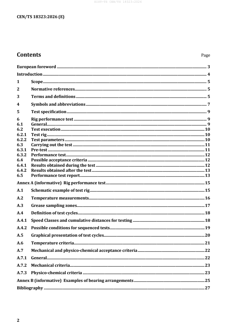
Contents Page
European foreword . 3
Introduction . 4
1 Scope . 5
2 Normative references . 5
3 Terms and definitions . 5
4 Symbols and abbreviations . 7
5 Test specification . 9
6 Rig performance test . 9
6.1 General. 9
6.2 Test execution . 10
6.2.1 Test rig . 10
6.2.2 Test parameters . 10
6.3 Carrying out the test . 11
6.3.1 Pre-test . 11
6.3.2 Performance test . 12
6.4 Possible acceptance criteria . 12
6.4.1 Results obtained during the test . 12
6.4.2 Results obtained after the test . 13
6.5 Performance test report . 13
Annex A (informative) Rig performance test . 15
A.1 Schematic example of test rig . 15
A.2 Temperature measurements . 16
A.3 Grease sampling zones . 17
A.4 Definition of test cycles . 18
A.4.1 Speed Classes and cumulative distances for testing . 18
A.4.2 Possible conditions for sequenced tests . 19
A.5 Graphical presentation of test cycles . 20
A.6 Temperature criteria. 21
A.7 Mechanical and physico-chemical acceptance criteria . 22
A.7.1 General. 22
A.7.2 Mechanical criteria . 23
A.7.3 Physico-chemical criteria . 23
Annex B (informative) Examples of bearing arrangements . 25
Bibliography . 27
European foreword
This document (CEN/TS 18323:2025) has been prepared by Technical Committee CEN/TC 256
“Railway Applications”, the secretariat of which is held by DIN.
Attention is drawn to the possibility that some of the elements of this document may be the subject of
patent rights. CEN shall not be held responsible for identifying any or all such patent rights.
Any feedback and questions on this document should be directed to the users’ national standards body.
A complete listing of these bodies can be found on the CEN website.
According to the CEN/CENELEC Internal Regulations, the national standards organisations of the
following countries are bound to announce this Technical Specification: Austria, Belgium, Bulgaria,
Croatia, Cyprus, Czech Republic, Denmark, Estonia, Finland, France, Germany, Greece, Hungary, Iceland,
Ireland, Italy, Latvia, Lithuania, Luxembourg, Malta, Netherlands, Norway, Poland, Portugal, Republic of
North Macedonia, Romania, Serbia, Slovakia, Slovenia, Spain, Sweden, Switzerland, Türkiye and the
United Kingdom.
Introduction
EN 12082-1 was created for specifying performance testing of conventional railway wheelset bearings
which means bearings mounted on a rotating axle and fixed in a non-rotating housing. Therefore, the
main acceptance criteria defined by EN 12082-1 are temperatures measured in the stationary load zone
of the outer rings. However, in case of some single wheel or axle bridge arrangements this is not
possible as in those applications, the outer ring is rotating. That means that the non-rotating load zone
is on the inner rings.
Due to technical reasons (e.g. higher Hertzian pressures, lower heat transfer) it is the bearing inner ring
which runs warmer than the outer ring regardless of which is the rotating ring. Operating bearing
temperatures are in general higher if bearings are preloaded which is often the case for axle bridge
bearings.
While this informative document focusses on how to test bearings with rotating outer ring, its existence
does neither imply that the execution of the described test is normative for applications with rotating
outer rings, nor does it specify under which conditions the test needs to be carried out. The content of
the document and particularly the proposed test success criteria are still under technical development
and cannot be finally specified before more practical experience is available.
1 Scope
This document specifies a possible test setup and test methodology on how bearing arrangements can
be tested in which the bearing outer ring instead of the inner ring is the rotating component. The
bearing arrangement can be based on cartridge bearings but also on a symmetric or asymmetric
combination of single row roller bearings which do not constitute a self-contained unit.
This document focuses on grease lubricated bearing arrangements. A test setup for oil lubricated
bearing arrangements is different. The document also suggests test acceptance criteria based on the
thermal behaviour of the bearings which takes the special loading and application conditions into
consideration.
This document offers the possibility to be referred to if bearing arrangements with rotating outer ring
undergo performance testing in line with EN 12082-1 for conventional bearings. The necessary type
and extent of testing are specified by the deployment procedure specified in EN 12082-2, with respect
to design requirements on the axle box and its components. compliance with EN 12080 and EN 12081
of bearing and grease is not a pre-requisite for the application of this document.
2 Normative references
There are no normative references in this document.
3 Terms and definitions
For the purposes of this document, the following terms and definitions apply.
ISO and IEC maintain terminology databases for use in standardization at the following addresses:
— ISO Online browsing platform: available at https://www.iso.org/obp/
— IEC Electropedia: available at https://www.electropedia.org/
3.1
wheel bearing
assembly consisting of the following major components: rolling bearing(s), grease and seal(s)
Note to entry: Wheels are not in the scope of this TS. Further components such as axle end cap components,
bearing sleeve, cover(s), distance rings, fasteners, labyrinth(s) may be also part of the assembly, but their
presence depends on the design of the single wheel or axle bridge arrangements.
3.2
rolling bearing
bearing operating with rolling motion between the parts, supporting load and moving in relation to
each other
3.3
cartridge bearing
rolling bearing with two or more rows of rolling elements within a self-contained unit, greased and
equipped with integral seals
3.4
grease
semi-solid lubricant, which consists of a thickener and additives dispersed in lubricating oil
3.5
seal
component that protects the rolling bearing(s) against ingress of water and dust and retains grease in
the rolling bearing(s)
3.6
roller set
assembly of cage and rollers
3.9
inboard bearing
with reference to a wheel bearing with more than one bearing row designates the bearing row closer to
the middle of the wheelset or the test rig
3.10
outboard bearing
with reference to a wheel bearing with more than one bearing row, designates the bearing row that is
next to the inboard bearing row to the outside direction
3.11
maximum operational test speed
v
max
maximum operational speed for normal service (in km/h)
3.12
nominal maximum rotational test speed
n
test
rotational speed (using the average wheel diameter) corresponding to V increased by 10 % (in rpm)
max
3.14
main line
railway network open to different types of rolling stock
3.15
urban rail
public transport systems permanently guided at least by one rail, intended for the operation of local,
urban and suburban passenger services with self-propelled vehicles and operated either segregated or
not from general road and pedestrian traffic
[SOURCE: CEN-CENELEC Guide 26:2013, Clause 1]
3.16
network
infrastructure, on which any railway undertaking can operate rolling stock
3.17
single wheel arrangement
arrangement without an axle between the two wheels, which allows the wheels to move vertically
independent to each other
3.18
axle bridge arrangement
arrangement where wheels are connected by a non-rotating beam instead of a rotation shaft
Note to entry: U-shaped axle bridges allow especially low vehicle floor
3.19
deployment process
methodical procedure of introducing an axlebox or a change to an axlebox into vehicle service
3.20
asymmetric bearing arrangement
bearing arrangement containing two or more rolling bearings which are dimensionally different
4 Symbols and abbreviations
For the purposes of this document, the symbols and abbreviations given in Table 1 and Table 2 apply.
Table 1 — Symbols
Symbol Unit Description
average wheel diameter between new and fully worn
d m
average
condition
d m wheel diameter in new condition
max
d m wheel diameter at limit of wear condition
min
F N force
F N reference vertical force applied per wheelset on the track
F N axial test force
a
Fan N nominal axial test force
F N radial test force
r
F N nominal radial test force
rn
2 2
g m/s acceleration due to gravity (9,81 m/s )
j - number of wheelsets per vehicle
n rpm rotational test speed
n rpm (see 3.12 maximum rotational test speed definition)"
test
estimated number of elementary trips needed to achieve
N -
trips
the performance test (based on nominal speed)"
N -
trips_adj
adjusted value of N to account for interruptions and
trips
Symbol Unit Description
variations in speed"
t s
1 time of one test cycle (seeA.6)
t s time of one elementary trip
ramp up or ramp down time from n = 0 → n = n or
test
t s
n = n → n = 0 during one elementary trip
test
t4 s time at rotational speed ntest during one elementary trip
t s stop time (n = 0)
time of one half load cycle of the alternating axial test
t s
force
time during which axial test force is applied (including
t s
ramp up and ramp down) within the period t
ramp up or ramp down time from F = 0 → F = F or
a a an
t s F = F → F = 0 during one half load cycle of the
8 a an a
alternating axial test force
t s axial test force recovery time
ambient temperature (it is practical to use a running
T °C average value for 30 min maximum to compensate for
a
rapid changes in the ambient temperature)"
measured temperature at a position z and then re-
T °C calculated to a temperature corresponding to an ambient
z20
temperature of 20 °C"
measured temperature at a position z (measured
T °C
zm
positions are loading zones and target zones)
v km/h speed of the vehicle
vmax km/h (see 3.11 maximum vehicle service speed definition)
Table 2 — Abbreviations
Abbreviation Description
ICP inductively coupled plasma (spectrometry)
MEP mounted end play
XRF X-ray fluorescence (spectrometry)
5 Test specification
The test specification consists of all the information describing test parameters and acceptance criteria.
The following requirements can be documented and included in the test specification:
a) performance test report recipients list;
b) quality management system accreditation and its scope;
c) interface drawing showing mounting conditions of all components as in-service;
d) boundary dimensions and interface tolerances of the rolling bearing(s);
e) MEP requirements;
f) conditions of production of the bearings (serial production, prototype);
g) grease designation, quantity and distribution, batch reference and production date;
h) specification of the test parameters according to 6.2.2;
i) deviations to the test parameters in A.4 and A.6;
j) required test distance;
k) deviations to the performance test report according to 6.5;
l) physico-chemical criteria limits.
6 Rig performance test
6.1 General
The purpose of the rig performance test is to check the satisfactory design and safe function of the
rolling bearing during a sequence of simulated journeys.
The test consists of putting a pair of wheel bearings, assembled as for operating conditions, on the test
rig and subjecting them to one or more sequence(s) of repeated loading cycles determined from the test
specification.
During rig operation (during a sequence), the rolling bearings are subjected to constant radial force and
dynamic axial force.
Before the performance test, a pre-test can be carried out. It is intended to observe the thermal
behaviour of the wheel bearing during the grease migration at the beginning of the rig test.
The performance test consists of repeating identical cycles up to an agreed cumulative distance. The
number of cycles and the required test distance reflect the service conditions of the intended
application. Throughout the test, the performance of the wheel bearing can be monitored by
measurement of temperatures. Absolute and relative temperatures can be compared with limits.
Finally, on completion of the test, the bearings and the grease can be inspected.
6.2 Test execution
6.2.1 Test rig
The test rig can apply testing conditions which are derived from the service operating conditions and
ensures accurate monitoring of the rolling bearings under test.
The test rig can include:
a) an axle or two axle journals on which inner rings of the rolling bearings are mounted
b) a dummy wheel in which the outer rings of the rolling bearings are mounted
c) rotation mechanism to apply the nominal test speed n to the dummy wheel
test
d) device for measuring the rotational speed of the dummy wheel n
e) device arranged to subject each rolling bearing to a radial force F = F
r rn
f) measuring device to monitor this radial test force F ;
r
g) device arranged to subject each rolling bearing to a dynamic axial force F ;
a
h) measuring device to monitor this dynamic axial test force F ;
a
i) ventilation equipment to simulate the cooling in operation;
j) sensors permitting temperature measurement:
— at loaded zone centrically to each bearing row in contact with inner ring bore. For this, usage of
a hollow shaft is recommended. Typical position is shown in Figure A.2;
— optional on dummy wheel surface. Non-contact measuring principle can be used for this
optional measuring position;
— of the ambient air stream which is directed at each dummy wheel measured at the outlet of the
cooling fans (see Figure A.1).
Examples of test rigs are shown in A.1.
6.2.2 Test parameters
6.2.2.1 General
The test parameters can be specified based on the operating conditions of the vehicles to be equipped
with the rolling bearings:
a) Static nominal radial test force F ;
rn
b) Dynamic nominal axial test force F ;
an
c) axial test force recovery time: t , in s;
d) wheel diameter new: d and at the limit of wear: d , in m;
max min
e) maximum operational speed: vmax, in km/h;
f) pre-test procedure;
g) required test distance, in km.
6.2.2.2 Rotational test speed
The maximum rotational test speed n (in rpm), maintained most of the time during the test, is that of
test
a half worn wheel and where the rotational speed is equal to the maximum operational vehicle speed
v , increased with a safety margin of 10 %.
max
110×𝑣𝑣
𝑚𝑚𝑚𝑚𝑚𝑚
𝑛𝑛 = (1)
𝑡𝑡𝑡𝑡𝑡𝑡𝑡𝑡
6×𝜋𝜋×𝑑𝑑
𝑚𝑚𝑎𝑎𝑎𝑎𝑎𝑎𝑚𝑚𝑎𝑎𝑎𝑎
where
𝑑𝑑 =(𝑑𝑑 +𝑑𝑑 ) (2)
𝑎𝑎𝑣𝑣𝑡𝑡𝑎𝑎𝑎𝑎𝑎𝑎𝑡𝑡 𝑚𝑚𝑚𝑚𝑚𝑚 𝑚𝑚𝑎𝑎𝑚𝑚
The tolerances are specified in A.5.
Since the speed may vary within tolerances specified in A.5 the number of elementary trips N need to
trips
be adjusted to N to evaluate the acceptance criteria in A.6.
trips_adj
6.2.2.3 Radial and axial forces
The test forces are applied to each rolling bearing to simulate operation conditions as closely as
possible.
As the formulas in EN 12082-1:2025, A.4, do not consider the load situation of axle brid
...