

FprEN 913
(Main)Gymnastic equipment - General safety requirements and test methods
- Abstract
This document specifies general safety requirements and test methods for all pieces of gymnastic and sports equipment and for all pieces of equipment for the use of physical education, training and competition, intended for use supervised by a competent person and not specified in other, individual standards.
- Status
- Not Published
- Publication Date
- 02-Dec-2026
- Technical Committee
- CEN/TC 136 - Sports, playground and other recreational equipment
- Drafting Committee
- CEN/TC 136/WG 22 - Gymnastic and playing field equipment
- Current Stage
- 5020 - Submission to Vote - Formal Approval
- Start Date
- 13-Aug-2026
- Due Date
- 25-Nov-2025
- Completion Date
- 13-Aug-2026
- Directive
- 2001/95/EC - General product safety

FprEN 913 is a CEN draft European Standard for gymnastic equipment and other sports equipment used in physical education, training and competition. It specifies general safety requirements and test methods for equipment intended to be used under the supervision of a competent person and not covered by a more specific product standard. The document brings together the basic hazards, the marking and instruction rules, and the test methods used to check entrapment, stability, strength and padding shock absorption.
What does FprEN 913 specify?
FprEN 913 sets the common safety baseline for supervised gymnastic and sports equipment. It covers the general requirements in the main clauses and adds detailed test methods and guidance in the annexes.
The document is organized as follows:
| Part | What it covers |
|---|---|
| Clause 1 | Scope |
| Clause 2 | Normative references |
| Clause 3 | Terms and definitions |
| Clause 4 | Risk assessment |
| Clause 5 | General safety requirements |
| Clause 6 | Marking and warning label |
| Clause 7 | Manufacturer instructions |
| Annex A | Determination of entrapment |
| Annex B | Mechanical loading for determination of stability and strength |
| Annex C | Determination of shock absorption of padding |
| Annex D | Introduction to risk assessment |
| Annex E | Inspection and maintenance |
| Annex ZA | Relationship with Regulation 2023/988/EC |
Clause 5.7 and 5.8 point product-specific friction, abrasion and ergonomics requirements to the relevant equipment standards where they exist.
What are the key requirements of FprEN 913?
FprEN 913 focuses on avoiding the main injury mechanisms in supervised use: entrapment, crushing, impact, instability, poor marking and unclear instructions. The clauses matter in practice because they tell manufacturers what to design, what to test, and what to document before equipment is placed on the market or into service.
Risk assessment and hazard coverage
Clause 4 bases the risk assessment on EN ISO 12100:2010 and identifies 12 hazard categories, including crushing, shearing, cutting, entanglement, impact, abrasion, weak structure, unintended movement, unsuitable ergonomics and wrong or missing information. In practice, this means the designer or assessor should think beyond one single test and look at how the equipment can fail or be misused in real use.
Materials and surface finish
Clause 5.1 requires materials to be selected and protected so that structural integrity is maintained until the next maintenance inspection. Clause 5.2 then requires smooth welds, no sharp or pointed parts, covered bolt threads in accessible areas, and rounded edges where protrusions can be reached by the user. This matters because small details such as exposed threads, rough welds or sharp corners are common injury points during normal handling and exercise.
Openings, entrapment and moving parts
Clause 5.3 requires the equipment to prevent head, neck and finger entrapment. It uses Annex A probe and template tests for completely bound openings, V-shapes and partially bound openings above the stated height, and it also checks openings close to hand-contact areas for finger entrapment risk. Clause 5.3 also requires that moving parts do not create crushing, shearing or pinching points during use or deflection, and that floor fixings do not leave hazardous openings when the equipment is detached from the floor.
Stability and strength
Clause 5.4 says stability and strength shall be verified by calculation or by the test procedures in Annex B unless a more specific product standard gives other rules. The clause sets the idea that equipment must not collapse, fracture or deform in a way that creates a new safety hazard, and that unfixed body sections must remain together during stability testing. In practice, this is the core check for whether the equipment can safely carry the intended users and loads.
Adjustment devices and top padding
Clause 5.5 requires adjustment devices to prevent accidental changes during use and to keep operating levers out of the user’s free space. Clause 5.6 requires top padding to be tested in accordance with Annex C and limits the measured peak acceleration. For a user, this means adjustments should stay where set, and padding should reduce the impact level to the stated limit.
Marking, warning labels and instructions
Clause 6 requires each piece of gymnastic equipment to be marked with the relevant European Standard number, producer identification, year of manufacture and the number of users intended for the equipment. Transport systems also need safe working loads and intended use. Clause 6.2 requires a warning label where there is a shearing or crushing risk during set-up or transport, and Clause 7 requires written instructions for assembly, installation, transport, storage and maintenance in the language of the country of use.
What terms does FprEN 913 define?
FprEN 913 defines the basic safety language used throughout the document so that testing and risk assessment are applied consistently.
- Hazard - a potential source of harm.
- Risk - the combination of the likelihood of harm and the severity of that harm.
- Body mass - the mass of the person or persons using the equipment.
- Static load - the load from the equipment structure, added weights and prestressed components.
- Dynamic factor - a factor that accounts for increased effective body mass during a dynamic movement.
- Safety factor - a factor used to cover uncertainty in body loading and dynamic factor, but not material or manufacturing variation.
- Ready for use - the condition where assembly is complete and the equipment is placed in position.
- Entrapment - a hazard where a body or part of a body can become trapped.
- V-shape - a partially bound opening treated as a neck-entrapment case regardless of its exact shape.
Who uses FprEN 913?
FprEN 913 is used by producers, designers, test houses, inspectors, operators and maintenance teams working with gymnastic and sports equipment. Producers use it to design equipment and write the required instructions, while test houses use the annex methods to check entrapment, loading and padding performance.
Inspectors and operators use the document for risk assessment, routine checks, operational inspections and main inspections. The standard is relevant where equipment is intended for supervised use in physical education, training and competition, including equipment that is not covered by a more specific individual standard.
What changed in FprEN 913 from the previous edition?
FprEN 913 states that it will supersede EN 913:2018+A1:2021. The significant technical changes listed are a new Clause 6 on marking and warning label, an update of Annex A, and an update of Annex ZA.
Which standards are used with FprEN 913?
FprEN 913 relies on a small set of referenced standards for loads, risk assessment and test instrumentation, and it also points readers to related gymnastic equipment standards for product-specific rules.
- EN 1991-1-1:2025, EN 1991-1-3:2025, EN 1991-1-4:2005 and EN 1991-1-5:2025 - provide self-weight, snow, wind and thermal load data used in Annex B when variable loads have to be included.
- EN ISO 12100:2010 - provides the general risk-assessment basis used in Clause 4 and discussed further in Annex D.
- ISO 6487:2015 - provides the instrumentation class used for the padding shock-absorption test in Annex C.
- EN 1176-1:2017+A1:2023 - is cited as the source for the entrapment dimensions and test logic used in Clause 5.3 and Annex A.
- Related gymnastic equipment standards named in the document - EN 914, EN 915, EN 916, EN 12196, EN 12197, EN 12346, EN 12432, EN 12655, EN 13219 and DIN 33959 cover specific apparatus types and provide the product-specific requirements that this general standard defers to.
- CEN ISO/TR 7250-2 and EN 81-20 - are used in Annex B notes to support the body-mass data used for loading calculations.
What does the FprEN 913 document contain?
FprEN 913 contains formula-based loading calculations, tabulated body-mass and dynamic-factor data, and step-by-step test procedures rather than only general principles. Annex A gives probe-and-template methods for head, neck and finger entrapment, with figures showing how to place the probes and templates.
Annex B gives the stability and strength loading method, including the test-force formula, the loading area, loading time and the way to report tilting, fracture and residual deflection. Annex C describes the padding drop test with an indenter, accelerometer and repeated impacts, and Annex D and E provide practical guidance for risk assessment, inspection and maintenance.
Relations
- Effective Date
- 13-Dec-2023
Frequently Asked Questions
FprEN 913 is a draft published by the European Committee for Standardization (CEN). Its full title is "Gymnastic equipment - General safety requirements and test methods". This standard covers: This document specifies general safety requirements and test methods for all pieces of gymnastic and sports equipment and for all pieces of equipment for the use of physical education, training and competition, intended for use supervised by a competent person and not specified in other, individual standards.
This document specifies general safety requirements and test methods for all pieces of gymnastic and sports equipment and for all pieces of equipment for the use of physical education, training and competition, intended for use supervised by a competent person and not specified in other, individual standards.
FprEN 913 is classified under the following ICS (International Classification for Standards) categories: 97.220.30 - Indoor sports equipment. The ICS classification helps identify the subject area and facilitates finding related standards.
FprEN 913 has the following relationships with other standards: It is inter standard links to EN 913:2018+A1:2021. Understanding these relationships helps ensure you are using the most current and applicable version of the standard.
FprEN 913 is associated with the following European legislation: EU Directives/Regulations: 2001/95/EC, 2023/988/EU, 92/59/EEC; Standardization Mandates: M/507. When a standard is cited in the Official Journal of the European Union, products manufactured in conformity with it benefit from a presumption of conformity with the essential requirements of the corresponding EU directive or regulation.
FprEN 913 is available in PDF format for immediate download after purchase. The document can be added to your cart and obtained through the secure checkout process. Digital delivery ensures instant access to the complete standard document.
Standards Content (Sample)
SLOVENSKI STANDARD
oSIST prEN 913:2025
01-september-2025
Gimnastična oprema - Splošne varnostne zahteve in preskusne metode
Gymnastic equipment - General safety requirements and test methods
Turngeräte - Allgemeine sicherheitstechnische Anforderungen und Prüfverfahren
Matériel de gymnastique - Exigences générales de sécurité et méthodes d'essai
Ta slovenski standard je istoveten z: prEN 913
ICS:
97.220.30 Oprema za dvoranske športe Indoor sports equipment
oSIST prEN 913:2025 en,fr,de
2003-01.Slovenski inštitut za standardizacijo. Razmnoževanje celote ali delov tega standarda ni dovoljeno.
oSIST prEN 913:2025
oSIST prEN 913:2025
DRAFT
EUROPEAN STANDARD
prEN 913
NORME EUROPÉENNE
EUROPÄISCHE NORM
July 2025
ICS 97.220.30 Will supersede EN 913:2018+A1:2021
English Version
Gymnastic equipment - General safety requirements and
test methods
Matériel de gymnastique - Exigences générales de Turngeräte - Allgemeine sicherheitstechnische
sécurité et méthodes d'essai Anforderungen und Prüfverfahren
This draft European Standard is submitted to CEN members for enquiry. It has been drawn up by the Technical Committee
CEN/TC 136.
If this draft becomes a European Standard, CEN members are bound to comply with the CEN/CENELEC Internal Regulations
which stipulate the conditions for giving this European Standard the status of a national standard without any alteration.
This draft European Standard was established by CEN in three official versions (English, French, German). A version in any other
language made by translation under the responsibility of a CEN member into its own language and notified to the CEN-CENELEC
Management Centre has the same status as the official versions.
CEN members are the national standards bodies of Austria, Belgium, Bulgaria, Croatia, Cyprus, Czech Republic, Denmark, Estonia,
Finland, France, Germany, Greece, Hungary, Iceland, Ireland, Italy, Latvia, Lithuania, Luxembourg, Malta, Netherlands, Norway,
Poland, Portugal, Republic of North Macedonia, Romania, Serbia, Slovakia, Slovenia, Spain, Sweden, Switzerland, Türkiye and
United Kingdom.
Recipients of this draft are invited to submit, with their comments, notification of any relevant patent rights of which they are
aware and to provide supporting documentation.
Warning : This document is not a European Standard. It is distributed for review and comments. It is subject to change without
notice and shall not be referred to as a European Standard.
EUROPEAN COMMITTEE FOR STANDARDIZATION
COMITÉ EUROPÉEN DE NORMALISATION
EUROPÄISCHES KOMITEE FÜR NORMUNG
CEN-CENELEC Management Centre: Rue de la Science 23, B-1040 Brussels
© 2025 CEN All rights of exploitation in any form and by any means reserved Ref. No. prEN 913:2025 E
worldwide for CEN national Members.
oSIST prEN 913:2025
prEN 913:2025 (E)
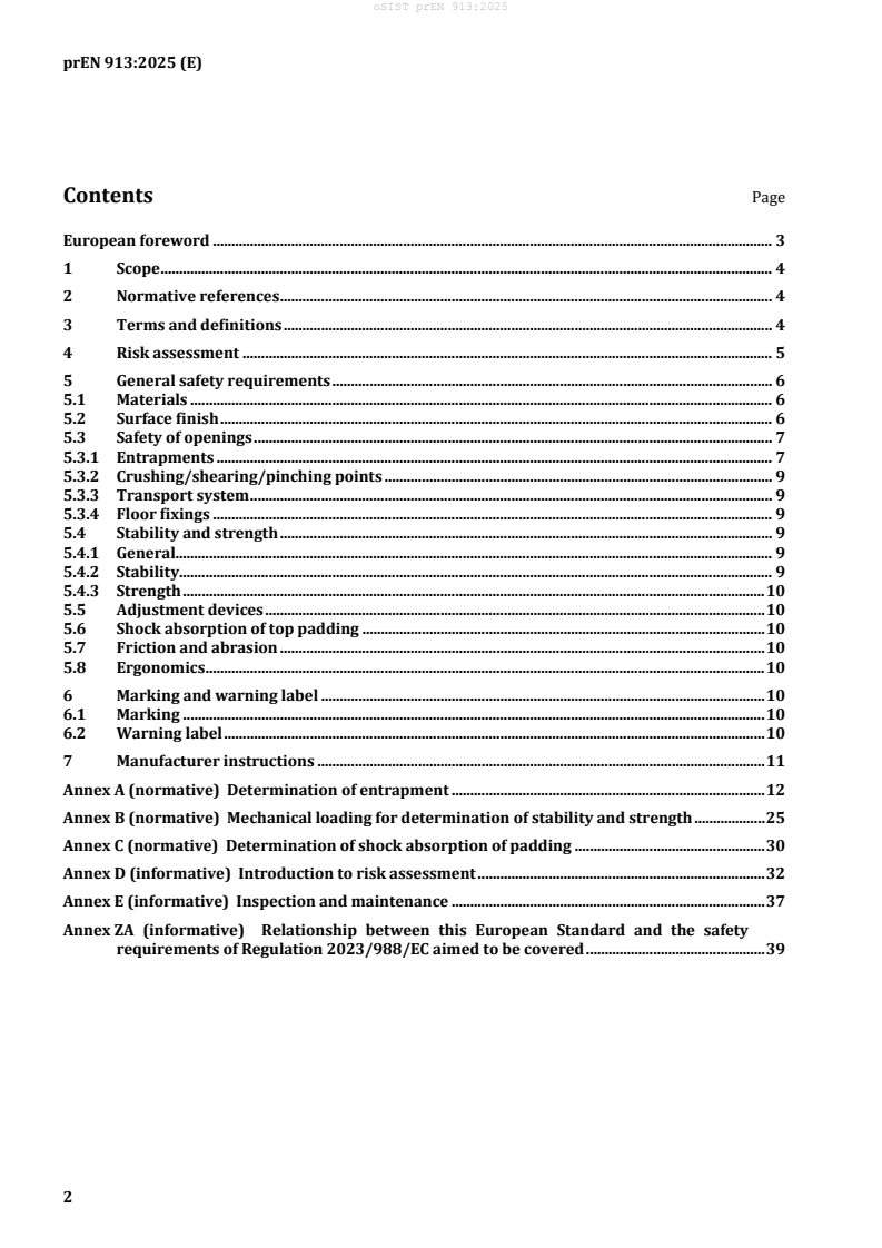
Contents Page
European foreword . 3
1 Scope . 4
2 Normative references . 4
3 Terms and definitions . 4
4 Risk assessment . 5
5 General safety requirements . 6
5.1 Materials . 6
5.2 Surface finish . 6
5.3 Safety of openings . 7
5.3.1 Entrapments . 7
5.3.2 Crushing/shearing/pinching points . 9
5.3.3 Transport system . 9
5.3.4 Floor fixings . 9
5.4 Stability and strength . 9
5.4.1 General. 9
5.4.2 Stability . 9
5.4.3 Strength . 10
5.5 Adjustment devices . 10
5.6 Shock absorption of top padding . 10
5.7 Friction and abrasion . 10
5.8 Ergonomics . 10
6 Marking and warning label . 10
6.1 Marking . 10
6.2 Warning label . 10
7 Manufacturer instructions . 11
Annex A (normative) Determination of entrapment . 12
Annex B (normative) Mechanical loading for determination of stability and strength . 25
Annex C (normative) Determination of shock absorption of padding . 30
Annex D (informative) Introduction to risk assessment . 32
Annex E (informative) Inspection and maintenance . 37
Annex ZA (informative) Relationship between this European Standard and the safety
requirements of Regulation 2023/988/EC aimed to be covered . 39
oSIST prEN 913:2025
prEN 913:2025 (E)
European foreword
This document (prEN 913:2025) has been prepared by Technical Committee CEN/TC 136 “Sports,
playground and other recreational facilities and equipment”, the secretariat of which is held by DIN.
This document is currently submitted to the CEN Enquiry.
This document will supersede EN 913:2018+A1:2021.
prEN 913:2025 includes the following significant technical changes with respect to
EN 913:2018+A1:2021:
— new Clause 6, “Marking and warning label”;
— update of Annex A;
— update of Annex ZA.
This document has been prepared under a standardization request addressed to CEN by the European
Commission. The Standing Committee of the EFTA States subsequently approves these requests for its
Member States.
For the relationship with EU Legislation, see informative Annex ZA, which is an integral part of this
document.
oSIST prEN 913:2025
prEN 913:2025 (E)
1 Scope
This document specifies general safety requirements and test methods for all pieces of gymnastic and
sports equipment and for all pieces of equipment for the use of physical education, training and
competition, intended for use supervised by a competent person and not specified in other, individual
standards.
2 Normative references
The following documents are referred to in the text in such a way that some or all of their content
constitutes requirements of this document. For dated references, only the edition cited applies. For
undated references, the latest edition of the referenced document (including any amendments) applies.
EN 1991-1-1:2025, Eurocode 1 - Actions on structures - Part 1-1: Specific weight of materials, self-weight
of construction works and imposed loads for buildings
EN 1991-1-3:2025, Eurocode 1 — Actions on structures — Part 1-3: General actions — Snow loads
EN 1991-1-4:2005, Eurocode 1: Actions on structures — Part 1-4: General actions — Wind actions
EN 1991-1-5:2025, Eurocode 1: Actions on structures — Part 1-5: General actions — Thermal actions
3 Terms and definitions
For the purposes of this document, the following terms and definitions apply.
ISO and IEC maintain terminology databases for use in standardization at the following addresses:
— ISO Online browsing platform: available at https://www.iso.org/obp/
— IEC Electropedia: available at https://www.electropedia.org/
3.1
hazard
potential source of harm
[SOURCE: EN ISO 12100:2010, 3.6]
3.2
risk
combination of probability of occurrence of harm and the severity of that harm
[SOURCE: EN ISO 12100:2010, 3.12]
3.3
body mass
mass of the person(s) using the equipment
3.4
static load
load acting on the equipment due to its structure, added weights and pre-stressed components
As impacted by EN 1991-1-4:2005/A1:2010 and EN 1991-1-4:2005/AC:2010
oSIST prEN 913:2025
prEN 913:2025 (E)
3.5
dynamic factor
factor to take account of the increase in effective body mass during a dynamic movement
3.6
safety factor
factor intended to cover uncertainties in the body loading and dynamic factor used, and which does not
cover allowance for variations in materials and manufacturing processes
3.7
variable load
load due to factors other than the static and body loads
3.8
ready for use
when the assembly is completed, and the equipment is placed in position
3.9
crushing point
place where parts of the equipment can move against each other, or against a fixed area so that persons,
or parts of their body, can be crushed
3.10
shearing point
place where part of the equipment can move past a fixed or other moving part, or past a fixed area so
that persons, or parts of their body, can be cut
3.11
entrapment
hazard presented by the situation in which a body, or part of a body can become trapped
3.12
V-shape
partially bound opening subject to neck entrapment test regardless to its real shape (V, U, square, etc.)
4 Risk assessment
The assessment of risks has been based on EN ISO 12100:2010. Twelve categories of hazard or sources
of hazard have been considered relevant to gymnastic equipment. These are as follows:
a) crushing;
b) shearing;
c) cutting and severing;
d) entanglement and trapping;
e) impact;
f) stabbing or puncture;
g) friction and abrasion;
oSIST prEN 913:2025
prEN 913:2025 (E)
h) insufficient mechanical strength;
i) use of unsuitable material;
j) unintended movement, including sliding;
k) unsuitable ergonomic design;
l) wrong or missing information.
NOTE See also Regulation (EU) 2023/988.
5 General safety requirements
5.1 Materials
Materials shall be selected and protected such that the structural integrity of the equipment
manufactured from them is not affected before the next relevant maintenance inspection. For more
information on inspection and maintenance see Annex E.
NOTE 1 The provisions relating to certain materials in this document do not imply that other equivalent
materials are unsuitable in the manufacture of multi-sports equipment.
The selection of materials and their use should be in accordance with the appropriate European
Standards where applicable.
In the choice of a material or substance for equipment, consideration should be given to the eventual
disposal of the material or substance having regard to any possible environmental toxic hazard.
NOTE 2 See also Regulation (EU) 2023/988.
5.2 Surface finish
There shall be no protruding nails, projecting wire rope terminations or pointed or sharp-edged
components. Rough surfaces should not present any risk of injury. All welds shall be smooth. Protruding
bolt threads within any accessible part of the equipment shall be permanently covered, e.g. dome
headed nuts. Nuts and bolt heads that project less than 8 mm are permitted in non-accessible parts,
provided they are free from burrs.
Corners, edges and projecting parts within the space occupied by the user that protrude more than
8 mm, and which are not shielded by adjacent areas that are not more than 25 mm from the end of the
projecting part, shall be rounded off. The minimum radius of the curve shall be 3 mm.
Figure 1 shows examples of protection for nuts and bolts and permissible protruding parts. Figure 2
shows examples of non-permissible protruding parts.
This requirement is intended only to prevent injuries caused by unintended contact with components.
oSIST prEN 913:2025
prEN 913:2025 (E)
Dimensions in millimetres
a) Examples of protection for nuts and bolts
b) Examples of permissible protruding parts
Figure 1 — Examples of permissible parts
Dimensions in millimetres
a) Uncovered protruding exterior screw thread
b) Unprotected, overhanging sharp-edged (hard) equipment part
Figure 2 — Examples of non-permissible protruding parts
5.3 Safety of openings
5.3.1 Entrapments
5.3.1.1 General
Equipment shall be designed to prevent head, neck and finger entrapments.
NOTE All dimensions given hereafter are copied from EN 1176-1:2017+A1:2023.
oSIST prEN 913:2025
prEN 913:2025 (E)
5.3.1.2 Head entrapment/strangulation
Completely bound openings with a lower edge more than 600 mm above the floor shall be tested in
accordance with A.1.
E (small head) shall not pass through any opening unless it also allows the passage of the probe D (large
head).
NOTE The two exceptions are given due to practical experience and to align the test closer to the former
EN 913 tests.
5.3.1.3 Neck entrapment
V-shapes in height of 600 mm or more above the floor (see Figure 3) shall be constructed so that one of
the following conditions exist:
1) When tested in accordance with A.4.1.2 first phase, opening does not allow insertion of the
template’s B-portion for its full thickness, width or length.
2) When tested in accordance with A.4.1.2 second phase, the opening shall conform to one of the
following requirements:
— Range 1: When the template apex contacts the bottom, the depth of the V-shape shall either be
less than the length of the template to the underside of the shoulder section or allow insertion of
the whole template, including the shoulder section.
— Range 2: When the template apex contacts the bottom, the depth of the V-shape shall be less
than the ‘A’ portion of the template. If the opening is deeper, the opening above the ‘A’ portion
shall allow insertion of the shoulder section of the template.
— Range 3: No template test requirements.
Dimensions in millimetres
Key
A floor
B equipment
arrow points of contact during test’s second phase
Figure 3 — Determining the height of the V-shape
oSIST prEN 913:2025
prEN 913:2025 (E)
5.3.1.4 Finger entrapment
Openings which are located closer than 90 mm from those parts of the equipment, that the user is
intended to touch with their hands, when tested in accordance with A.4.1.2, shall conform to one of the
following:
1) The 8 mm finger rod does not fit into the opening.
2) The 25 mm finger rod passes through the opening or to the bottom of the recess.
3) If only the 8 mm finger rod fits into the recess, while being at the bottom of the recess, it can be
bended to less than 45° angle from the adjacent surface and moved full circle along conical surface
(see Figure A.4).
NOTE When the user is exercising, the risk of finger entrapment is related to the speed of the user more than
opening’s physical height from the floor. When fast movement does not exist, openings less than 1 000 mm from
the floor are typically of low risk.
5.3.2 Crushing/shearing/pinching points
When the equipment is in use and its parts can move relative to each other or to the floor, either by
design or through deflection or bending under load, there shall be no shearing/crushing/pinching
points that can create a danger for head, neck, or finger.
These requirements shall be assessed by carrying out a visual inspection and probes specified in
Annex A.
5.3.3 Transport system
Where a transport system is used, it shall be considered in the risk assessment. The risk assessment
shall consider disengagement, crushing, shearing and unintentional dropping. Transport systems shall
be marked according to Clause 7. For more information on risk assessment see Annex D.
5.3.4 Floor fixings
Any floor fixings shall be designed in such a way that they will not protrude from the floor level, nor
provide openings equal to or greater than 12 mm in diameter unless they are covered with a flush
fitting cover, when the equipment is not attached to the floor.
NOTE Should a risk be seen through the opening, a cover might be required even at less than 12 mm.
5.4 Stability and strength
5.4.1 General
Unless specified elsewhere in individual equipment standards, verification of the stability and strength
of equipment shall be achieved by engineering calculation or by testing in accordance with the
procedures specified in Annex B.
5.4.2 Stability
For stability testing where the normal action produces a destabilizing force in a horizontal direction, e.g.
vaulting, the theoretical horizontal test force shall be calculated using the formula given in B.1.8. The
calculation shall give a result which is ≥ 35 % of the self-weight of the equipment or 50 N, whichever is
the greater.
Unless specified elsewhere in individual equipment standards, for equipment with unfixed body
sections an actual test shall be carried out with a theoretical horizontal test force of 65 % of the
oSIST prEN 913:2025
prEN 913:2025 (E)
theoretical test force calculated according to the formula given in B.1.8, or 50 N, whichever is the
greater. Unfixed body sections shall not become separated.
5.4.3 Strength
When tested in accordance with Annex B, equipment shall not collapse or fracture, or show any
permanent deformation that would result in an additional safety hazard as described in the standard.
5.5 Adjustment devices
Any adjustment devices shall prevent accidental changes during use of the device or the equipment.
None of the operating levers shall protrude into the user's free space.
This shall be assessed by carrying out a visual inspection and operation of the adjustment device.
5.6 Shock absorption of top padding
Shock absorption of top padding shall be determined in accordance with Annex C. When tested in
accordance with the method specified in Annex C, the peak acceleration shall not exceed 500 m/s , if
not specified in other, individual equipment standards.
5.7 Friction and abrasion
Requirements are related to the specific gymnastic and sports equipment and dealt within the
appropriate European Standards (where applicable).
5.8 Ergonomics
Requirements are related to the specific gymnastic and sports equipment and dealt within the
appropriate European Standards (where applicable).
6 Marking and warning label
6.1 Marking
All gymnastic equipment shall bear the following marking:
a) number of the relevant European Standard;
b) name, trademark or other means of identification of the producer, retailer or importer;
c) year of manufacture;
d) number of users for which the equipment is intended.
Any other information regarding the intended use is related to the specific gymnastic and sports
equipment and dealt within the appropriate European Standards (where applicable).
Transport systems shall be marked with:
a) safe working loads;
b) identified intended use.
6.2 Warning label
When setting up or transport of equipment there could be risk for shearing or crushing. Those points
shall be highlighted with a warning label.
oSIST prEN 913:2025
prEN 913:2025 (E)
7 Manufacturer instructions
The producer shall provide written instructions for the safe assembly, installation, transportation,
storage and maintenance in the appropriate language(s) of the country in which the gymnastic and
sports equipment is to be installed and used.
Further requirements are related to the specific gymnastic and sports equipment and dealt within the
appropriate European Standards (where applicable).
oSIST prEN 913:2025
prEN 913:2025 (E)
Annex A
(normative)
Determination of entrapment
A.1 Principle
Test probes of specified dimensions are offered to potential entrapment points, and a note is made of
whether or not they can be inserted.
In situations of doubt when using the probes relating to the tolerance an accurate measurement should
be made to ensure the opening is in accordance with the nominal dimension.
All tests shall be performed in the most onerous way.
A.2 Apparatus
Test probes of dimensions as described in Figure A.1.
A.3 Conditioning and test temperature
Condition the equipment and test probes for a minimum of 3 h at the test temperature of (23 ± 2) °C.
A.4 Procedure
A.4.1 Head and neck entrapment
A.4.1.1 General
The equipment shall be set up ready for use. The probe shall be applied with its longitudinal axis
perpendicular to the plane of the opening. No rotation of the probe about any axis other than the
longitudinal axis is permitted. Translations perpendicular to the longitudinal axis of the probe are
allowed. The longitudinal axis of the probe is considered to coincide with the longest axis of the probe’s
handle.
A.4.1.2 Test procedure
A.4.1.2.1 General
Insert the probe E (small head) and probe D (large head) see Figure A.1 into each opening more than
600 mm above a standing surface. If probe E passes the opening, probe D shall also pass through the
opening.
Insert the probe E (small head) and probe D (large head) see Figure A.2 into each opening more than
600 mm above a standing surface. The probe shall not become stuck. If the probe can enter the opening
it shall touch the bottom of the opening (see Figure A.2 and Figure A.3).
A.4.1.2.2 V-shaped openings and partially bound openings
Insert the probe E (small head) and probe D (large head) see Figure A.1 into each opening more than
600 mm above a standing surface along the direction of its median line. The probe shall not become
stuck. If the probe can enter the opening it shall touch the bottom of the opening (see Figure A.2 and
Figure A.3).
oSIST prEN 913:2025
prEN 913:2025 (E)
A.4.2 Finger entrapment
Insert the 8 mm diameter finger probe (see Figure A.8) into each relevant opening and, if the probe
does not pass through, rotate it as illustrated in Figure A.9.
Record and report if the probe enters the opening and if it locks in any position when moved through
the conical arc shown in Figure A.9.
If the 8 mm diameter finger probe passes through the opening, apply the 25 mm diameter finger probe
(see Figure A.8).
Record and report if the 25 mm diameter finger probe passes through the opening and, if it does,
whether access is then given to another finger entrapment site.
No opening which presents a risk of finger entrapment is permissible. An opening is considered to
present a risk of finger entrapment if:
— it can accommodate the 8 mm probe but not the 25 mm probe; or
— its profile is such that the 8 mm probe can become locked in position; or
— 25 mm probe cannot be inserted a full 100 mm into the opening and the opening gives access to
another entrapment site.
A.5 Expression of results
A.5.1 General
Report all findings recorded under procedures A.4.1 and A.4.2.
Assess and report whether each opening assessed complied with the requirements of this document.
Unless stated otherwise, tolerances of the probes in this annex are as follows:
a) ± 1 mm for dimensions; and
b) ± 1° for angles.
In situations of doubt when using the probes relating to the tolerance an accurate measurement should
be made to ensure the opening is in accordance with the nominal dimension of the probe.
All tests shall be performed in the most onerous way.
A.5.2 Head and neck entrapment
A.5.2.1 Completely bound openings
A.5.2.1.1 Apparatus
Probes, as illustrated in Figure A.1.
oSIST prEN 913:2025
prEN 913:2025 (E)
Dimensions in millimetres
a) Probe E (small head)
b) Probe D (large head)
Key
1 handle
Figure A.1 — Probes for determination of head and neck entrapment in completely bound
openings
A.5.2.2 Procedure
Apply successively the probes as illustrated in Figure A.2 to each relevant opening. Record and report
the passage of any probe through the opening. If any of the probes are not freely passing through the
opening apply a force of (222 ± 5) N to the probe. Apply the probe with the axis perpendicular to the
plane of the opening.
oSIST prEN 913:2025
prEN 913:2025 (E)
or Pass
Pass
Fail
or
oSIST prEN 913:2025
prEN 913:2025 (E)
Key
1 probe E (small head)
2 probe D (large head)
Figure A.2 — Examples of procedures
A.5.3 Partially bound and V-shaped openings
A.5.3.1 Apparatus
Test template, as illustrated in Figure A.3.
Dimensions in millimetres
Key
A “A” portion of probe
B “B” portion of probe
B1 shoulder section
Figure A.3 — Test template for assessment of head and neck entrapment in partially bound and
V-shaped openings
oSIST prEN 913:2025
prEN 913:2025 (E)
A.5.3.2 Procedure
Position the ‘B’ portion of the test template between and perpendicular to the boundaries of the
opening, as shown in Figure A.2. Record and report whether the template fits within the boundaries of
the opening or, if it cannot be inserted to its full thickness.
If the test template can be inserted to a depth greater than the thickness of the template (45 mm), apply
the ‘A’ portion of the test template, so that its centre line is orientated to check the extremities of the
opening as well as the centreline.
Ensure that the plane of the test template is parallel and applied in line with the opening, as shown in
Figure A.2.
Insert the test template along the opening until its motion is arrested by contact with the boundaries of
the opening. Record and report the results including the angle of the template centreline relative to the
vertical and horizontal axes (see Figure A.2 as this will determine the pass/fail requirements given in
5.3.1. See Figure A.5, Figure A.6 and Figure A.7 for examples of the assessment for the different angular
ranges.
a)
oSIST prEN 913:2025
prEN 913:2025 (E)
b)
Key
1 accessible
2 not accessible
Figure A.4 — Method of insertion of the “B” portion of the test template
a)
oSIST prEN 913:2025
prEN 913:2025 (E)
b)
c)
Key
1 range 1
2 range 2
3 range 3
a
insertion angle for assessing the range
b
template centre line
c
check all insertion angles
A A-portion (see Figure A.3)
B B-portion (see Figure A.3)
Figure A.5 — Checking all insertion angles to determine range
oSIST prEN 913:2025
prEN 913:2025 (E)
Dimensions in millimetres
a) Passes if front section fully enters aperture to a maximum depth of (template shoulder depth)
265 mm
b) Fail
oSIST prEN 913:2025
prEN 913:2025 (E)
c) Pass
Key
> 600 mm more than 600 mm above the playing sur
...